4 minute read
2.6 O peration of the screed


2.6.3 Setting the paving width
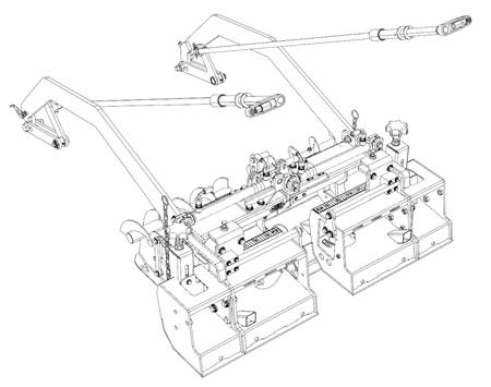
The machine is equipped with a left (43) and right (44) screed extension frame for setting the paving width. The required paving width can be set using the controls (2) and (3) on the dashboard.
The basic screed width is 800 mm (31.5 in), and each of the extendible screed extension is 250 mm (9.8 in) wide. The adjustable range of the paving width corresponds to the total width of both extendible screed extensions and amounts to 500 mm (19.7 in). The paving width can be adjusted in a maximum to minimum range value.
The paving width in the standard model of the machine is:
• Minimum paving width without reduction plates 800 mm (31.5 in)
• Maximum paving width without reduction plates: 1,300 mm (51.2 in)
Paving width with reduction plates is:
• Minimum paving width with reduction plates (centre of the machine): 250 mm (9.8 in)
• Maximum paving width with reduction plates: 750 mm (29.5 in)
Paving width with mechanical extension is:
• Minimum paving width with mechanical extension: 1150 mm (45.3 in)
• Maximum paving width with mechanical extension: 1650 mm (65 in)
Setting the paving width: Procedure for setting the required paving width on the left side of the screed:
• To increase the paving width on the left side, turn the paving width switch (2) to the left and hold it.
• Once released, the paving width switch (2) returns to the middle position and the screed stops in the required position.
• To decrease the paving width on the left side, turn the paving width switch (2) to the right and hold it.
• Once released, the paving width switch (2) returns to the middle position and the screed stops in the required position.
• Check the required setting of the paving width on the left side by checking the position on the left paving width indicator (51).
Procedure for setting the required paving width on the right side of the screed:
• To increase the paving width on the right side, turn the paving width switch (3) to the right and hold it.
• Once released, the paving width switch (3) returns to the middle position and the screed stops in the required position.
• To decrease the paving width on the right side, turn the paving width switch (3) to the left and hold it.
• Once released, the paving width switch (3) returns to the middle position and the screed stops in the required position.
• Check the required setting of the paving width on the right side by checking the position on the right paving width indicator (52).
When setting the required screed width, no one is allowed in the hazardous area of the machine. There is a risk of injury from the movement of the screed extensions. The safe distance from the machine is at least 5 m.
2.6 O peration of the screed
2.6.4 Setting the paving thickness
By setting the paving thickness, we can set a variable paving thickness in the range from 5 to 100 mm (0.2 – 3.9 in).
The maximum allowed difference in the paving thickness (H) on the left and right side of the machine can be 40 mm (1.6 in).
The paving thickness is set by setting the pitch angle of the screed.
The pitch angle is an angle between the base of the screed and the surface of the subgrade in the longitudinal direction of machine travel.
A larger pitch angle will cause a higher lift and this will cause a greater paving thickness.
To create a layer with the right or left crown (A), set a different paving thickness on both sides of the machine using the paving thickness controllers (47).
Procedure for setting the paving thickness:
• To increase the paving thickness on the left or right side, turn the paving thickness controller (47) in the clockwise direction.
• To decrease the paving thickness on the left or right side, turn the paving thickness controller (47) in the anti-clockwise direction.
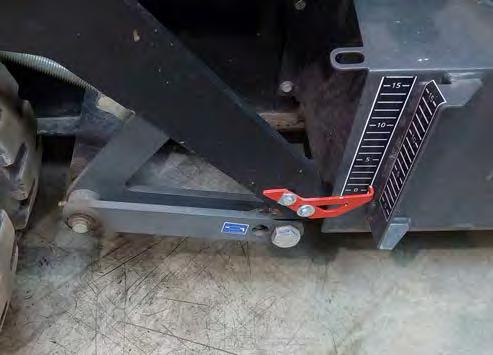
• During paving of the material check the setting of the paving thickness on the left and right side by checking the position of the paving thickness indicator (1) on the paving thickness scale (2).
Note
The paving thickness scale (2) is only used for informative measuring and the actual paving thickness must be measured behind the machine.
Every change in the paving thickness is manifested with a delay (after driving 2 – 6 length of the screed tow arms).
Procedure for setting the screed tow arms:
• The quantity of the material delivered to the area of augers can be affected by setting the screed tow arms depending on the grain size of the paved material.
Grain size 0 – 25 mm:
• The screed tow arms must be set in point (3).
Grain size 25 – 35 mm:
• The screed tow arms must be set in point (4).
When setting the required paving thickness, no one is allowed in the hazardous area of the machine.
There is a risk of injury from the movement of the screed. When setting the screed tow arms, there is a danger of injury caused by movement of the tow arms.
There is a risk of burns from the hot parts of the screed. When setting the screed tow arms, use the prescribed protective equipment.
The paving thickness scale (2) is only used for informative measuring and the actual paving thickness must be measured behind the machine.
2.6.5 Setting the roadway profile
Setting the roadway profile defines the cross shaping of the paved layer with the purpose to drain water from the road in a crosswise direction.
The roadway profile is measured in "%" and the positive “α” and negative “ß” roadway profile is distinguished.
• In case of the positive roadway profile, the centre of the layer lies above the edges of the layer. The roadway drains the water to both sides of the road.
• In case of the negative (super elevation) roadway profile, the centre of the layer lies below the edges of the layer. The roadway drains the water to the centre of the road.
The limit values of the roadway profile are different for the positive and negative ranges.
• The positive range may be set to a maximum of 3 %.
• The negative range may be set to a maximum of -2%.
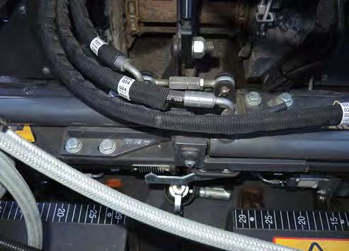
Setting the roadway profile:
• Set the roadway profile by setting the screw (1) on the screed of the machine.
• Ensure that the machine is standing on a level and firm surface.
• To increase the roadway profile, loosen the screw (1).
• To decrease the roadway profile, tighten the screw (1).
• Check the setting of the roadway profile on the scale (2).