4 minute read
Functional Description – Keypad

from Dynapac 275 DI TU Engine Asphalt Compactor DRA30 Operating & Maintenance Manual 4812333211 - PDF

Working mode Rotating beacon (Option)
Vibration, MAN/AUTO
Working lights
Sprinkler MAN/AUTO
Sprinkler Timer Horn
Engine speed selector (Not applicable)
RIGHT → AUTO Working lights Turns on the working lights of canopy.
OFF
LEFT → Working lights, ON
LEFT → Sprinkler manual
RIGHT → Sprinkler auto
LED LEFT → Sprinkler spray low
LED CENTER → Sprinkler spray medium
LED RIGHT → Sprinkler spray high
Engine speed selector Not Applicable this machine
Rotating beacon (Option)
LED
Starter Switch
The starter switch starts and stops the engine. There are three positions in the starter switch, they are:
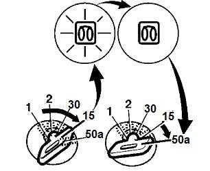
• OFF position: In this position all the electric systems and the engine are switched off, and the key can be removed
• ON position: In this position, Engine is on run mode Charging circuit and lamp circuit are energized
• Start position: In this position, the engine cranks Make sure to allow the switch to on position until the engine is started
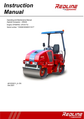
Throttle Lever
The throttle control regulates the speed of the engine Inforwardposition,theengineidlesandin the backward position, the engine runs with a full speed
Work/Transport mode
The 1st number button is used for work or transport mode selection. Press the button to turnon the work mode with Red illumination in button and press again to turn On the transport mode.
Emergency Stop
The emergency button is used to stop the engine in an emergency situation which it cannot be shut off in an usual manner. It switches off the engine and activates the brakes. The emergency stop aborts the entire control operation in a quicker way for the safety of the personnel
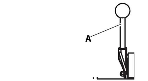
Sprinkler Switch
Figure
A. Sprinkler Manual/Auto
B. Sprinkler timer
Sprinkler timer will work only when AUTO mode Selected.
Forward/Neutral (FNR) Lever
Direction of travel and speed of the roller is regulated with the forward/reverse lever The machine speed increases or decreases in proportion to the position of the lever
Seat Buzzer
Seat buzzer beeps if the operator is not seated during the operation of the roller and it continues to beep until the operator is seated. If the buzzer beeps for long the brakes are activated and engine is forced to stop
Horn Button
The horn button is located on the switch assembly
Press the button to activate the horn
Drum Selector Switch
Depending on the Drum selector, the vibration is activated in the following places
Right side button Activates vibration for front drum.
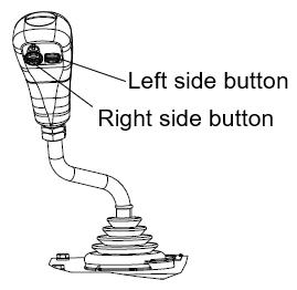
Left side button Activates vibration for rear drum.
Note – Only front Drum will not activate, for both Drum activation first need to activate Rear Drum then activate Front Drum.
Vibration Activation Switch
In first press, Vibration MAN mode is selected with RED illumination in left side & in second press, Vibration AUTO mode is selected with RED illumination in right side.
Fuse Box
The fuse box is located on the control column whichcontainsthe fusesfor theelectricalsystem. Fuses protect the electrical components from damage because of a short circuit Refer to electricalsystem forthe description andfunctions of the fuses
Driving Lights Switch
Push up, to switch on the driving lights and depress to switch on the parking lights In Intermediate position the lights are switched off.
Hazard Warning Lights Switch
Hazard warning lights are primarily used to warn other vehicles that there is a problem either with the roller, or there is a hazard in front of roller causing the operator to reduce speed quickly.
A Push up Position
B Intermediate position
C Depressed position
Rotating Beacon Switch (Optional)

Rotatingbeaconlightingisgenerallyusedtowarn the approaching machine of potential hazards, suchasmachinethat isstoppedormovingslower than the rate of the traffic
Depress the switch to switch on the rotating beacon
Working Lights Switch (Optional)
Depresstheswitchtoswitchontheworkinglights
Depress the switch to switch on the hazard warning lights
Direction Indicator Switch
The direction indicators are blinking lamps mounted near the left and right, front and rear cornersof theroller Depress the switch either left or right, to on the left or right indicators. In the intermediate position the function is shut off
Parking Brake On/Off Switch
The parking brake On/Off switch is used to activate the parking brake.
N o t e Parking brake must be activated while starting the engine Always activate the parking brake when the machine is stationary on a sloping surface
Control Panel
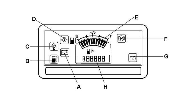
A Battery/charging E Fuel level
B Low fuel level F Parking brake lamp
C Engine water temperature G Glow plug
D Oil pressure, engine H Hour meter
Control Panel Warnings Symbols
Warning lights comes on when the starter switch is turned to the on position and should goes off once the engine has started If the lights comes on when the engine is running indicates a faulty condition
Designation Function Description
Battery charging indicator lamp
If light does not illuminate when ignition is switched on, illuminates after engine is started, the battery is not charging Contact maintenance personnel if the lamp comes on during tramming
Dieselengine lubricating oil pressure indicator lamp
Enginetemperature signal lamp
If the pressure is too low, the lamp comes on and the parking brake is applied In this event, switch the engine off immediately andrectifythecause Contactmaintenance personnel
The lamp comes on when the temperature is too high The engine must be switched off immediately and contact the maintenance personnel if the lamp comes on during tramming
Low fuel level indicator. This lamp comes on if the oil level is low in the fuel tank
Control Panel Notificationion Symbols
Notifications are displayed when the starter switch is turned to the on position and notifies that corresponding systems are operating.
Table
Designation Function Description
Parking brake indicator lamp
The light illuminates when the parking brake is activated
The fuel level gauge
The fuel level gauge monitors the level of fuel in the fuel tanks of the roller The fuel gauge is shown in increments of zero, 1/4, 1/2, 3/4, and one. When the indicator needle shows 1/4, the fuel tank should be filled
Hour meter
It displays the number of hours the engine has run