2 minute read
Engine Identification

from Dynapac 275 DI TU Engine Asphalt Compactor DRA30 Operating & Maintenance Manual 4812333211 - PDF

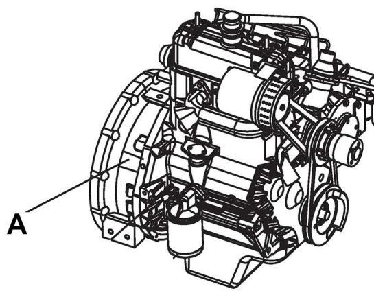
The engine identification plate located on flywheel housing near engine oil filter. The engine identificationplateprovidesmodelidentificationandotherimportantdataabout theengine Refertothe engine operation and maintenance manual for further information on the identification information Have the following engine data available when communicating with an authorized repair location or engine dealer The data on the engine identification plate is mandatory when sourcing service parts:
• Engine serial number
• Model
1.2 RollerDescription
DRA30 are two self-propelled vibratory tandem rollers in the three metric tonnes class featuring 1200 mm wide drums The machines are equipped with drive, brakes, and vibration on both drums
To permit optimum performance on a wide range of applications and site requirements, the roller is equipped with:
Diesel engine
Electrical system
Propulsionsystem/transmission
Brake system
Secondary/parkingbrake
Steering system
FOPS and ROPS/Canopy
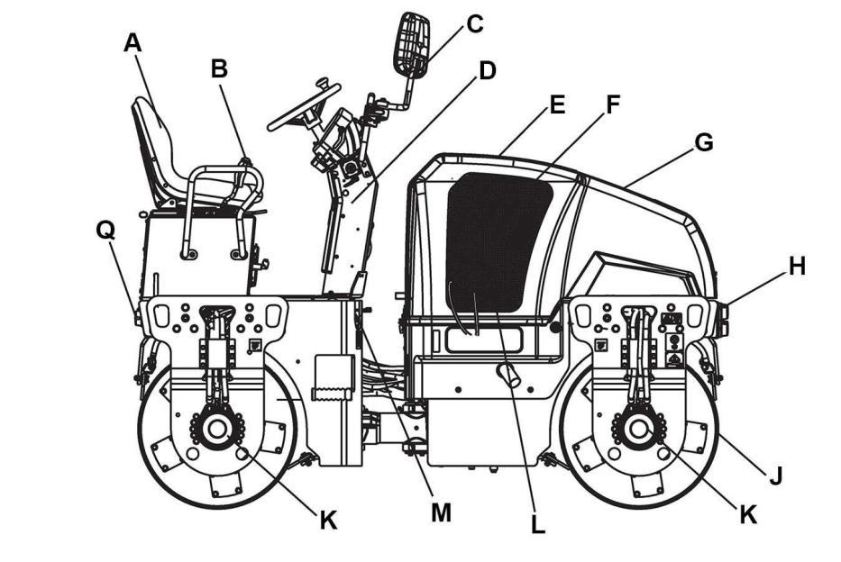
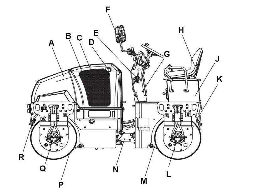
Identification of Major Components
Figure 1-6: Major Components Left Side
A Hood G Steeringconsole N Steering joint
B Engine H Seat P Drum
C Cooler J Platform Q Vibration motor
D Air Cleaner K Sprinkler system R Scrapper
E Throttle lever L Vibration motor
F Mirror (Optional) M Scrapper
Diesel Engine
The machine is equipped with a water-cooled, straight three cylinder, and four-stroke diesel engine
Electrical System
The roller is equipped with 12-V electrical system and 3-A AC alternator
A 100-A Power relay
B and C 30-A Main fuses
D Batterydisconnector switch
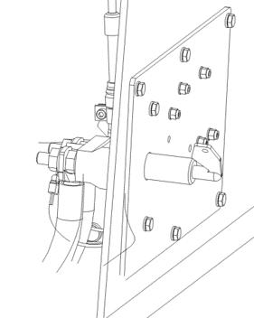
Main and Light Fuses
The main fuse and light fuse are placed near to the battery disconnector switch
On the same bracket, timer relay and 100-A power relay for stop solenoid are placed
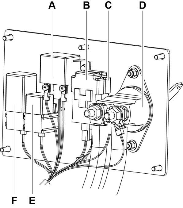
F3 Main fuse 30 A
F4 Fuse-starter relay 30 A
E 30-A Mini relay for starter
F Timer relay
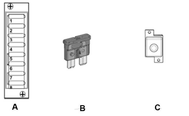
Fuse Boxes in Switch Box
The flat pin, type C (medium) fuses and first cavity 20-A fuse are used for driving lights
A Fuse box C Fuse for driving lights
B Fuse
1 Main fuse (Emergency/ Parking switch)
Brake system
The brake system consists of a service brake, secondary brake, and parking brake The service brakeishydrostaticandisactivatedbymovingthe control lever to neutral
Secondary/Parking Brake
The secondary and parking brake system consists of spring multiple disc brakes in the motors. The brakes are released with hydraulic pressure and are operated with a switch on the instrument panel.
Steering System
15 A
The steering system is a hydrostatic system. The control valve on the steering column distributes theflowtothecontrolcylinder, whichactuatesthe articulation
Thesteeringangleisproportionaltothedeflection of the steering wheel.
FOPS and ROPS
8 Spare 10 A
SSl No Function
1 Driving lights 20 A
2 Spare 10 A
Propulsion System/ Transmission
The propulsion system is a hydrostatic system with a hydraulic pump supplying two motors connected in parallel. The motors drive the front and rear drums
The speed of the machine is proportional to the deflection/angle of the control lever from neutral
FOPS is the abbreviation for Falling Object ProtectiveStructure(roofprotection)andROPSis the abbreviation for Roll Over Protective Structure If any part of the FOPS/ROPS structure's protectiveconstructiondisplays plastic deformationorcracks,theFOPS/ROPS structure must be replaced immediately. Never perform unauthorized modifications on the FOPS/ ROPS structure
Roller Applications
The DRA30 roller is built in accordance with international standards and recognized safety rules Nevertheless, misuse may constitute a risk to the life and limb of the user or third parties and may cause damage to the roller or other material property
The DRA30 roller must be used in accordance with its designated use as described in this manual. The roller must only be operated by trained; safety-conscious persons who are fully awareof risksinvolvedin operatingtheroller. Any functionaldisorders,especiallythoseaffectingthe safety of the roller, must be corrected immediately.
Designated Applications
The DRA30 roller is designed primarily for compaction of asphalt It has excellent compactioncapacityforreinforcement layersand bearing courses. The roller is mainly intended for compacting asphalt on streets and minor roads in towns It has sufficient capacity to follow a small asphalt paver
Non-Designated Applications
The DRA30 roller is not designed to use as a ladder, support, ora worksurface. it isnot used to carry or transport passengers or equipment The manufacturer/supplier cannot be held liable for any damage resulting from such use The risk of such use lies entirely with the user
Operating the DRA30 roller within the limits of its designated use also involves compliance with the inspection and maintenance directives contained in the operating manual