

TRANSMISSION OPERATIONS AND DIAGNOSTICS
CLICK HERE TO DOWNLOAD THE COMPLETE MANUAL
• Thank you very much for reading the preview of the manual.
• You can download the complete manual from: www.heydownloads.com by clicking the link below

• Please note: If there is no response to CLICKING the link, please download this PDF first and then click on it.
CLICK HERE TO DOWNLOAD THE
SAFETY PRECAUTIONS MAINTENANCE AND REPAIR
• The Service Manuals are updated on a regular basis, but may not reflect recent design changes to the product. Updated technical service information may be available from your local authorized Hyster® dealer. Service Manuals provide general guidelines for maintenance and service and are intended for use by trained and experienced technicians. Failure to properly maintain equipment or to follow instructions contained in the Service Manual could result in damage to the products, personal injury, property damage or death.
• When lifting parts or assemblies, make sure all slings, chains, or cables are correctly fastened, and that the load being lifted is balanced. Make sure the crane, cables, and chains have the capacity to support the weight of the load.
•Do not lift heavy parts by hand, use a lifting mechanism.
•Wear safety glasses.
• DISCONNECT THE BATTERY CONNECTOR before doing any maintenance or repair on electric lift trucks. Disconnect the battery ground cable on internal combustion lift trucks.
• Always use correct blocks to prevent the unit from rolling or falling. See HOW TO PUT THE LIFT TRUCK ON BLOCKS in the OperatingManual or the PeriodicMaintenance section.
•Keep the unit clean and the working area clean and orderly.
•Use the correct tools for the job.
•Keep the tools clean and in good condition.
• Always use HYSTERAPPROVED parts when making repairs. Replacement parts must meet or exceed the specifications of the original equipment manufacturer.
• Make sure all nuts, bolts, snap rings, and other fastening devices are removed before using force to remove parts.
• Always fasten a DO NOT OPERATE tag to the controls of the unit when making repairs, or if the unit needs repairs.
• Be sure to follow the WARNING and CAUTION notes in the instructions.
• Gasoline, Liquid Petroleum Gas (LPG), Compressed Natural Gas (CNG), and Diesel fuel are flammable. Be sure to follow the necessary safety precautions when handling these fuels and when working on these fuel systems.
• Batteries generate flammable gas when they are being charged. Keep fire and sparks away from the area. Make sure the area is well ventilated.
NOTE: The following symbols and words indicate safety information in this manual:

WARNING
Indicates a hazardous situation which, if not avoided, could result in death or serious injury.

CAUTION
Indicates a hazardous situation which, if not avoided, could result in minor or moderate injury and property damage.
On the lift truck, the WARNING symbol and word are on orange background. The CAUTION symbol and word are on yellow background.
TABLE OF CONTENTS
TABLE OF CONTENTS (Continued)
Series Code / Model Designation Reference Table
This section is for the following models:
Series Code
A238
H16.00XM-9, H16.00XM-12, H18.00XM-7.5, H18.00XM-9 H360-36HD, H360-48HD
B238 H16.00XM-9, H16.00XM-12, H18.00XM-7.5, H18.00XM-9 H360-36HD, H360-48HD
H019
J007
H13.00-16.0XM-6, H10.00-12.0XM-12EC
H8.00-12.00XM-6
J019 H13.00-16.00XM-6, H10.00-12.00XM-12EC
K007 H8.00-12.00XM-6, H10.00XMS-6
K019 H13.00-16.00XM-6
K019EC H6.00XM-12EC3, H7.00XM-12EC4
L007 H8.00-12.00XM-6
General
This manual provides information on operation and diagnostics of the ZF ERGOPOWER (WG161) Transmission as fitted on J007, K007, L007, H019, J019, K019, A238 and B238 series trucks.
The repair procedures for the transmission and control valve are shown in Transmission Repair (ZF-WG161) 1300SRM1456.
H300-360HD2, H360HD2-EC
H190-280HD2
H300-360HD2, H360HD2-EC
H190-280HD2, H230HDS
H210-250-48HD2, H300-360HD2
H360HD2-EC4
H190-280HD2, H250HD2
Electrical system diagrams are shown in Diagrams.
CLICK HERE TO DOWNLOAD THE COMPLETE MANUAL
• Thank you very much for reading the preview of the manual.
• You can download the complete manual from: www.heydownloads.com by clicking the link below
• Please note: If there is no response to CLICKING the link, please download this PDF first and then click on it.
CLICK HERE TO DOWNLOAD THE
Description
GENERAL
The function of the transmission is to transfer engine power from the engine flywheel to the drive wheels and to the hydraulic pump(s) that are attached to the transmission.
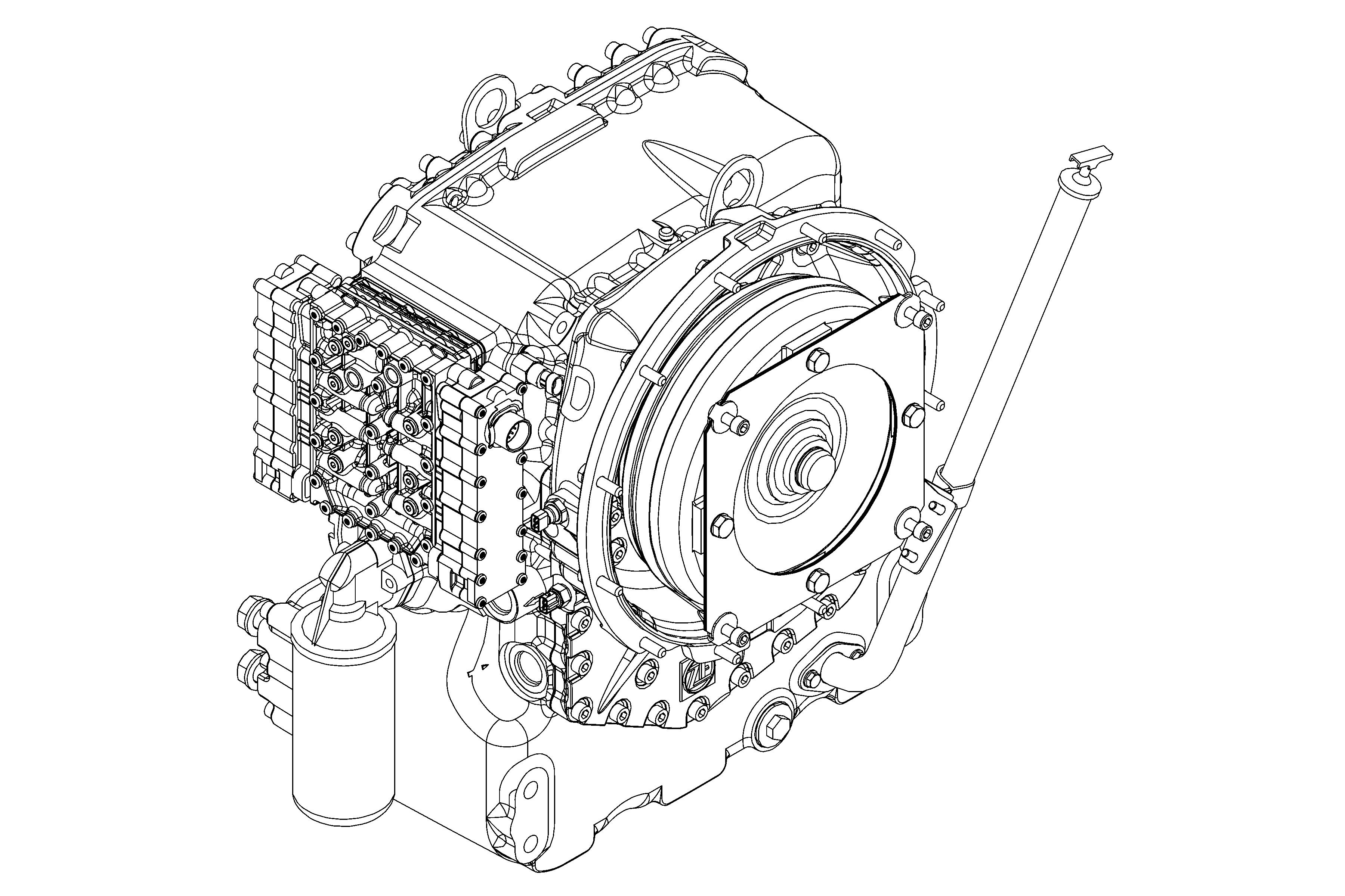
The engine flywheel is connected to the torque converter housing through a drive plate. See Figure 1.
The flexing properties of the drive plate reduce transfer of axial forces between engine crankshaft and torque converter. The torque converter drives the transmission pump and the PTO drives the attached pump(s) for the hydraulic system of the truck. The torque converter, transmission pump and hydraulic pump(s) turn at proportional engine speed.
The oil pressure generated by the transmission pump is used for lubrication, internal cooling, and hydraulic control of the transmission. Without oil pressure the transmission cannot function.
The torque converter hydraulically connects the engine flywheel with the transmission input shaft. It functions as a fluid clutch to smoothly transfer power from the engine to the transmission, and as a torque multiplier when speed difference between engine and transmission input shaft increases. The torque converter has a specific torque multiplication factor that matches the engine power characteristics. Speed difference between engine and transmission input shaft is a measure of engine power being transferred. With increasing speed difference, there is also an increased amount of heat generated in the converter. The heat generated is removed by the transmission oil which flows through the torque converter.
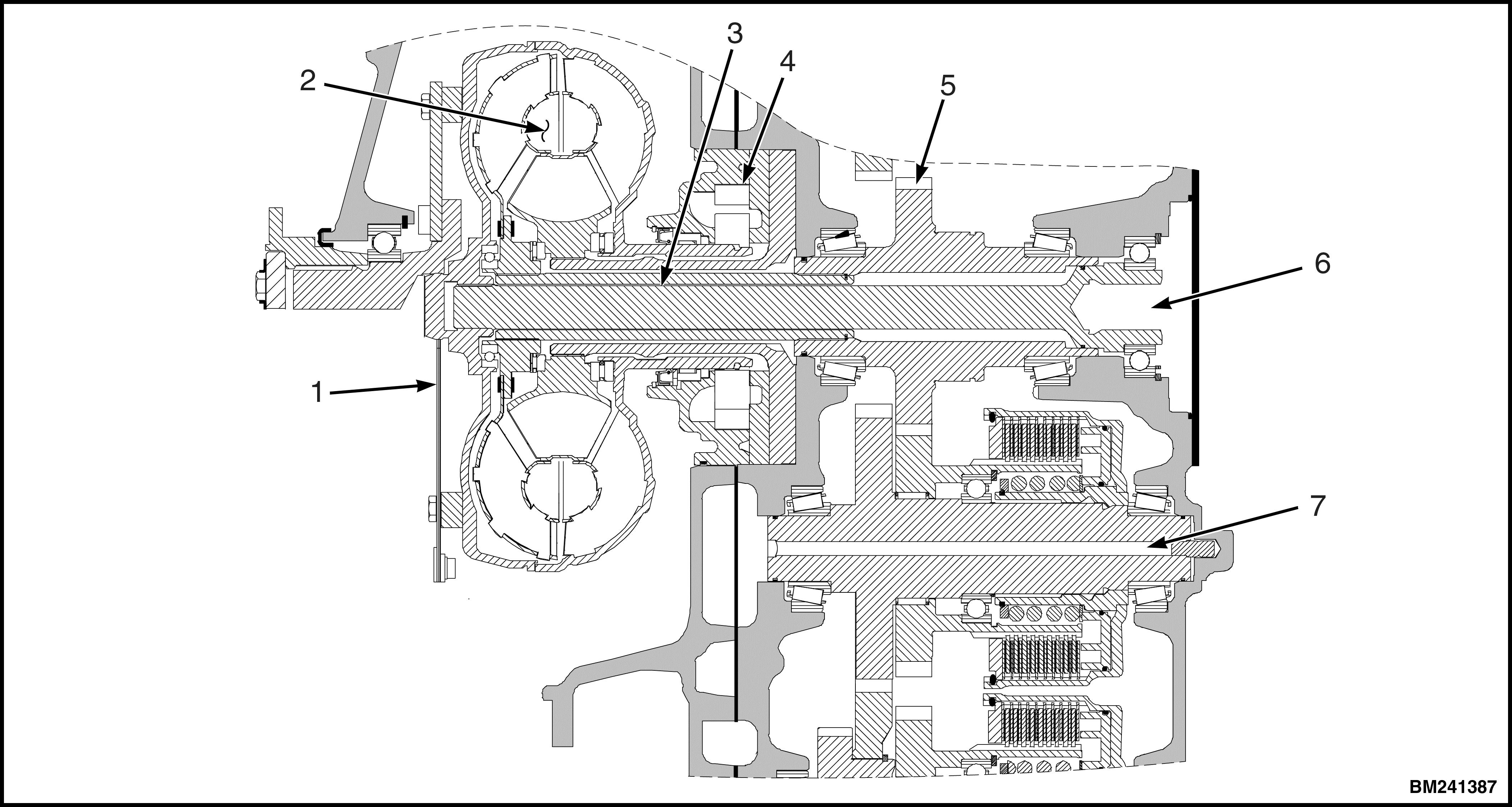
Figure 1. Torque Converter
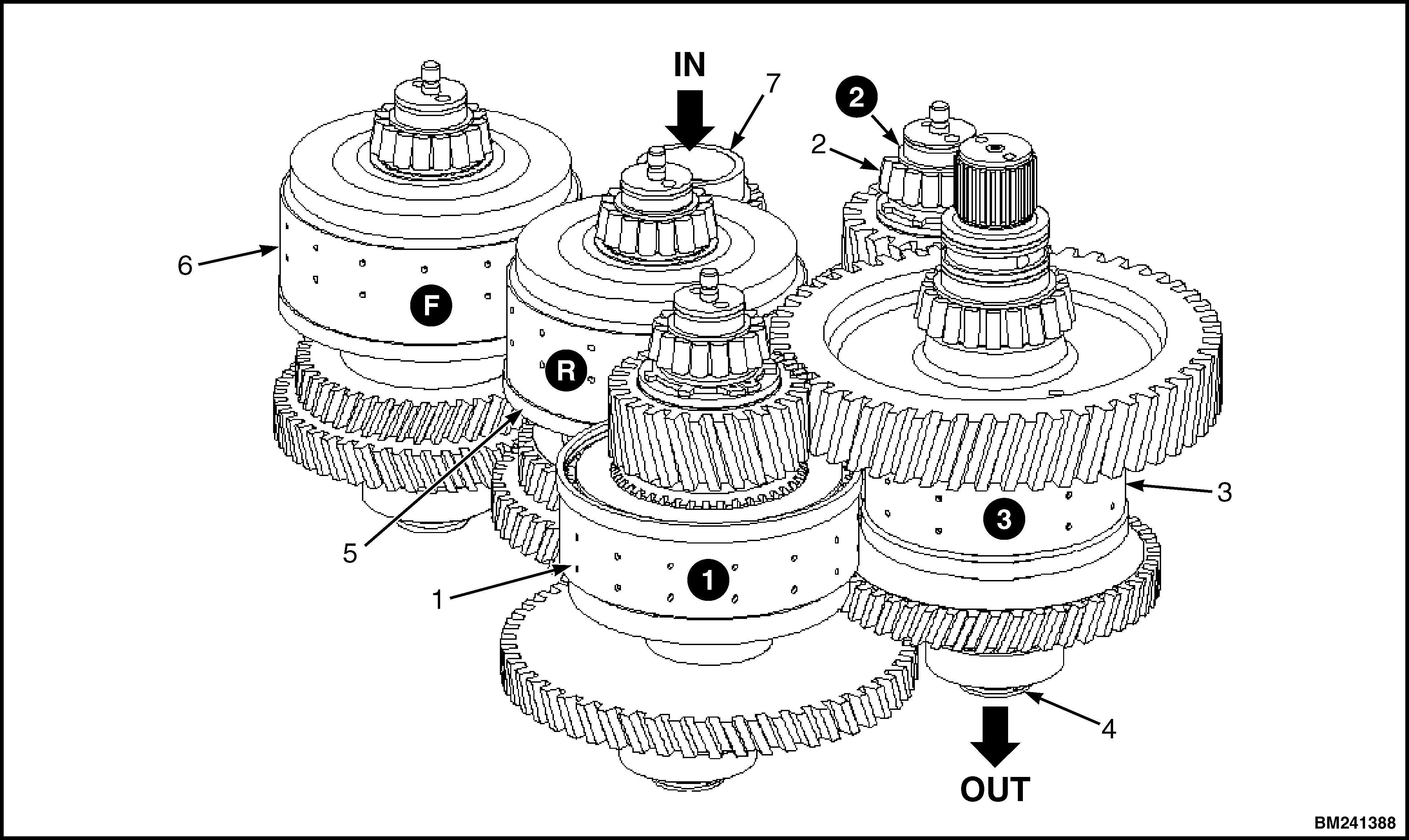
The different speed ratios between input shaft and drive shaft are obtained by engaging and disengaging different clutches. See Figure 2. Three groups of gears are continuously engaged with each other: the input gears, the interconnecting gears, and the output gears. See Figure 3.
If clutches belonging to one group would be engaged simultaneously, the transmission would lock. The clutches Forward and Reverse should not be engaged at the same time. Also, the speed clutches
for the 1st, 2nd, and 3rd speed should not be engaged at the same time. Erroneous clutch engagement is prevented by the transmission control system.
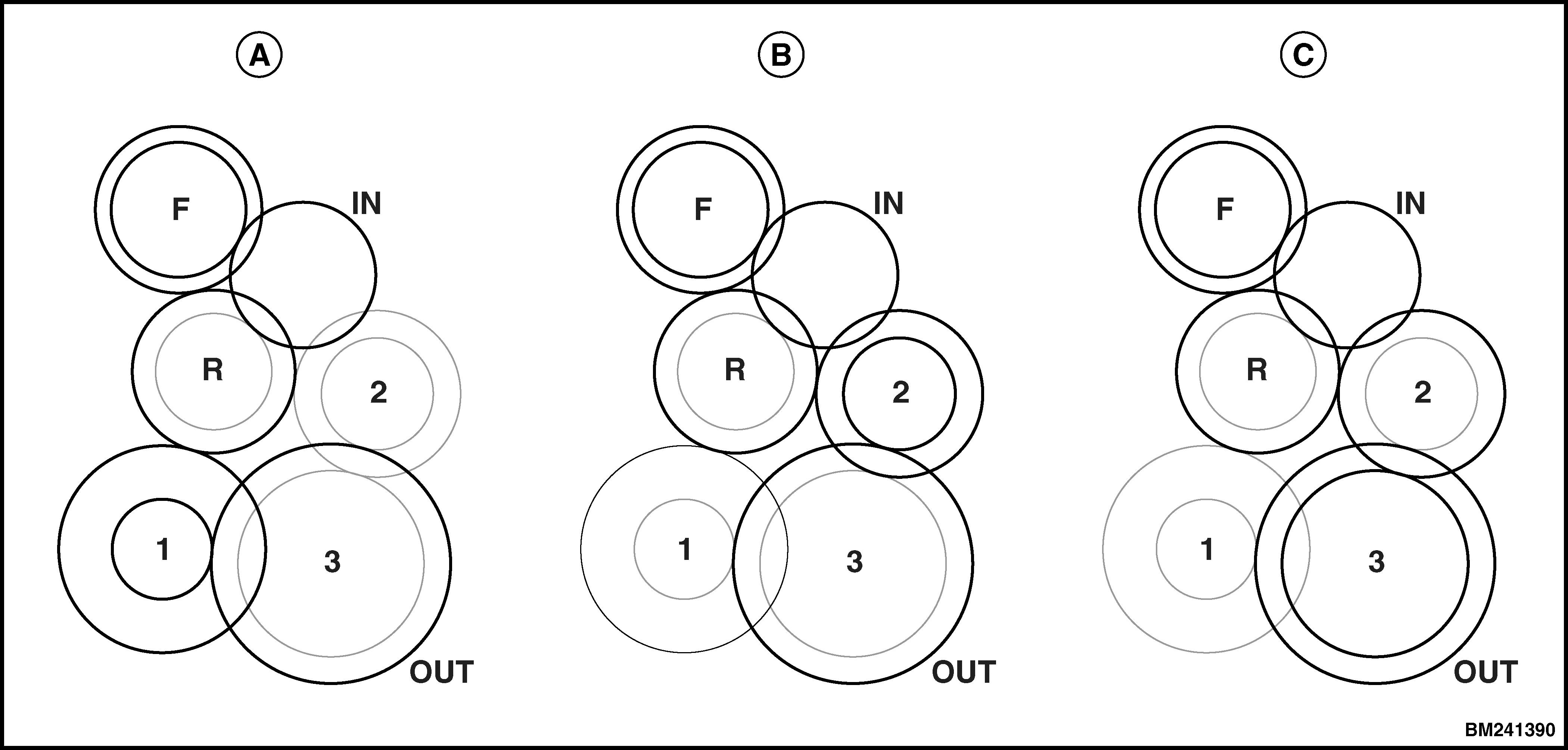
The different speeds are obtained by engaging either the forward or reverse clutch, and by engaging either one of the clutches for the 1st, 2nd, and 3rd speed. When the transmission is in NEUTRAL, all clutches are disengaged. See Figure 4.
5.REVERSE CLUTCH
6.FORWARD CLUTCH
7.INPUT SHAFT
1. 1ST GEAR CLUTCH
2. 2ND GEAR CLUTCH
3. 3RD GEAR CLUTCH 4.OUTPUT SHAFT
Figure 2. Gear Assembly

FORWARD 2ND GEAR
A. INPUT GEARS B. INTERCONNECTING GEARS
C. OUTPUT GEARS
Figure 3. Gear Engagement
A. FORWARD 1ST GEAR
B.
C. FORWARD 3RD GEAR
Figure 4. Gear Engagement for Selected Speeds
CLUTCH
The clutches consist of a drum which carries a piston and steel discs with external splines, and a hub which carries friction discs with internal splines. See Figure 5.
Friction discs and steel discs are installed in alternate order.
By pressurizing the clutch piston, the friction discs and steel discs are clamped together, which cause the hub and drum to rotate as one unit. Also the gears attached to the hub and clutch will rotate as one unit to transfer engine power.
When hydraulic pressure is released, the clutch return spring pushes the piston back against the clutch housing, which allows hub and drum to rotate independently. The drum, steel discs, piston, and return springs rotate at the same speed. The hub rotates at the same speed with the friction discs.

1.CLUTCH ASSEMBLY BEARING
2.CLUTCH SPRING
3.FRICTION DISC
4.PISTON SEAL
5.PISTON
6.CLUTCH DRUM
7.STEEL DISC
8.IDLER BEARING
9.CLUTCH HUB
Figure 5. Clutch Components
Operation
HYDRAULIC OPERATION
The transmission sump is the main reservoir for the transmission oil. The sump screen keeps large particles from entering the transmission pump. The pump is driven by the torque converter housing, which connects directly through splines.
A pressure relief valve in the pump supply line protects the system against pressures in excess of 35 to 45 bar (506.6 to 652.7 psi) .
The pump transfers oil through the transmission filter, and further to the Main Pressure Valve and the Clutch Valves.
The transmission filter is protected by a 5.5 to 8.5 bar (80 to 123.3 psi) bypass valve, which includes a sender that is connected with the trans-
mission controller. When the filter is clogged, the transmission controller triggers a fault code and activates the transmission warning light.
The Main Pressure Valve maintains a system pressure of 16 to 18.5 bar (232 to 268.3 psi) by relieving excess oil through the torque converter, oil cooler and lubrication system. Most of pump oil supply volume is used for cooling and lubrication. This volume is about 105 liter (28 gal) per minute at an engine speed of 2000 rpm.
System Pressure is used to pressurize the clutches. Applied pressure to the clutches is regulated by the Clutch Valves, which receive an electrical signal from the transmission controller to activate the operating valve through pilot pressure.
Pilot Pressure is maintained at 9 bar (131 psi) by the Pressure Reducing Valve. See Figure 6.
CLICK HERE TO DOWNLOAD THE COMPLETE MANUAL
• Thank you very much for reading the preview of the manual.
• You can download the complete manual from: www.heydownloads.com by clicking the link below
• Please note: If there is no response to CLICKING the link, please download this PDF first and then click on it.
CLICK HERE TO DOWNLOAD THE
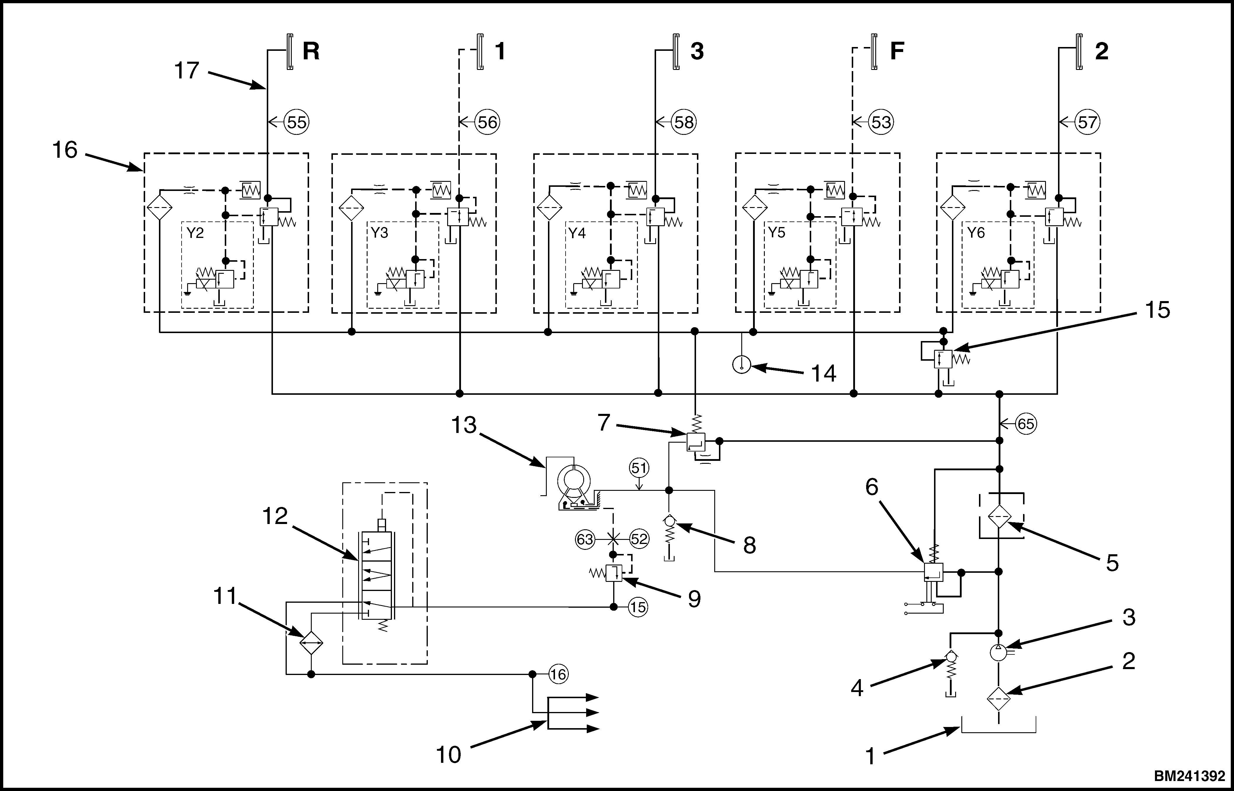
1.SUMP
2.SCREEN
3.PUMP
4.PRESSURE RELIEF VALVE
5.FILTER
6.FILTER BYPASS VALVE
7.MAIN PRESSURE VALVE
8.TORQUE CONVERTER SAFETY VALVE
9.TORQUE CONVERTER BACK PRESSURE VALVE
10.LUBRICATION AND COOLING
11.OIL COOLER
12.THERMOSTATIC BY-PASS VALVE
13.TORQUE CONVERTER
14.TEMPERATURE SENSOR
15.PRESSURE REDUCING VALVE
16.CLUTCH VALVE
17.CLUTCH
Figure 6. Hydraulic Diagram
Clutch Valve
The function of the clutch valve is to transfer system pressure to the clutches according the electrical signal from the transmission controller. See Figure 8.
The varying signal from the transmission controller operates the pressure regulator proportionally. When activated, the pressure regulator closes, causing pilot pressure at the operating valve to rise, resulting in the transfer of system pressure to the clutch. When de-activated, the pressure regulator opens, causing pilot pressure to drain to tank, which closes the operating valve and drains clutch pressure.
The clutch valve includes a flow restrictor, which limits oil supply. This limited oil supply allows pressure to drop quick enough when the pressure regulator opens.
A hydraulic damper limits pressure peaks when the pressure regulator closes. See Figure 7.
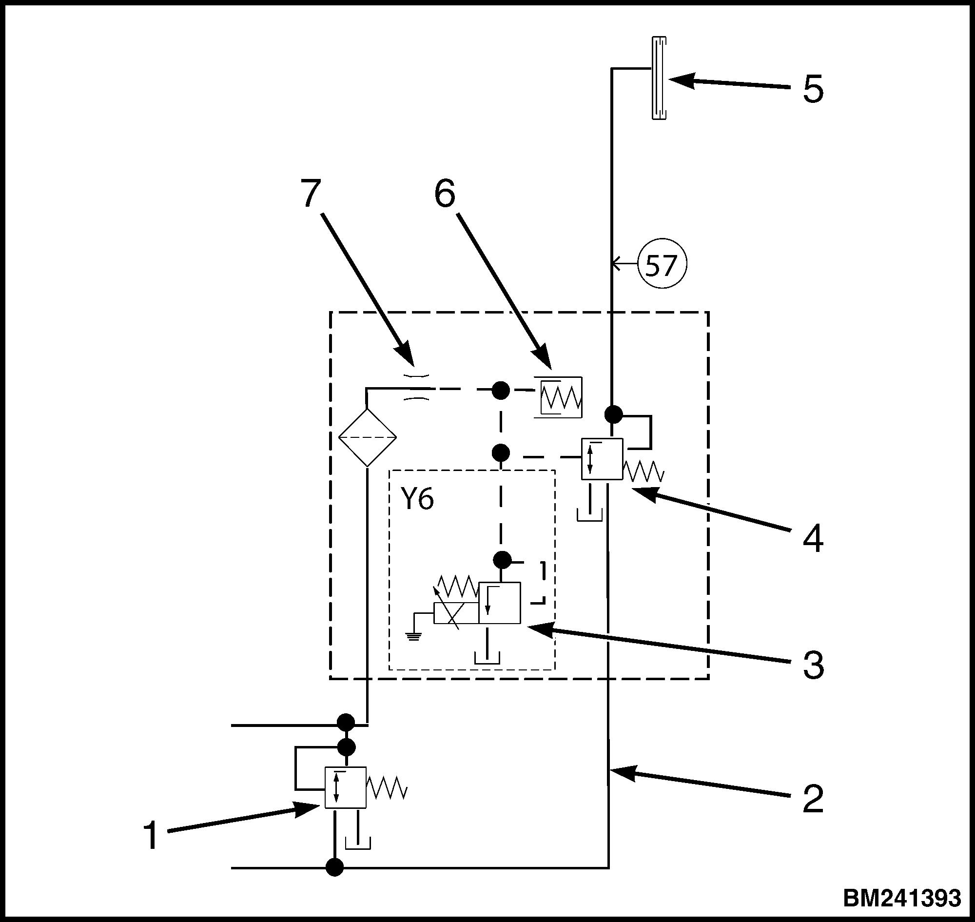
1.PRESSURE REDUCING VALVE
2.SYSTEM PRESSURE
3.PRESSURE REGULATOR
4.OPERATING VALVE
5.CLUTCH
6.DAMPER
7.RESTRICTOR
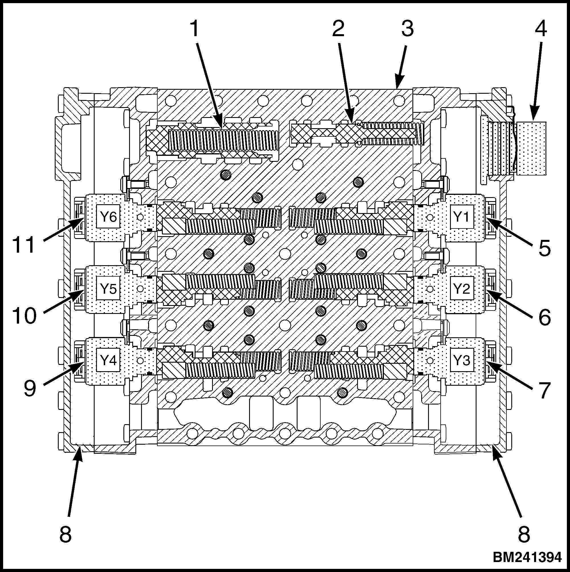
1.MAIN PRESSURE VALVE
2.PRESSURE REDUCING VALVE
3.HYDRAULIC CONTROL VALVE
4.CABLE HARNESS CONNECTOR
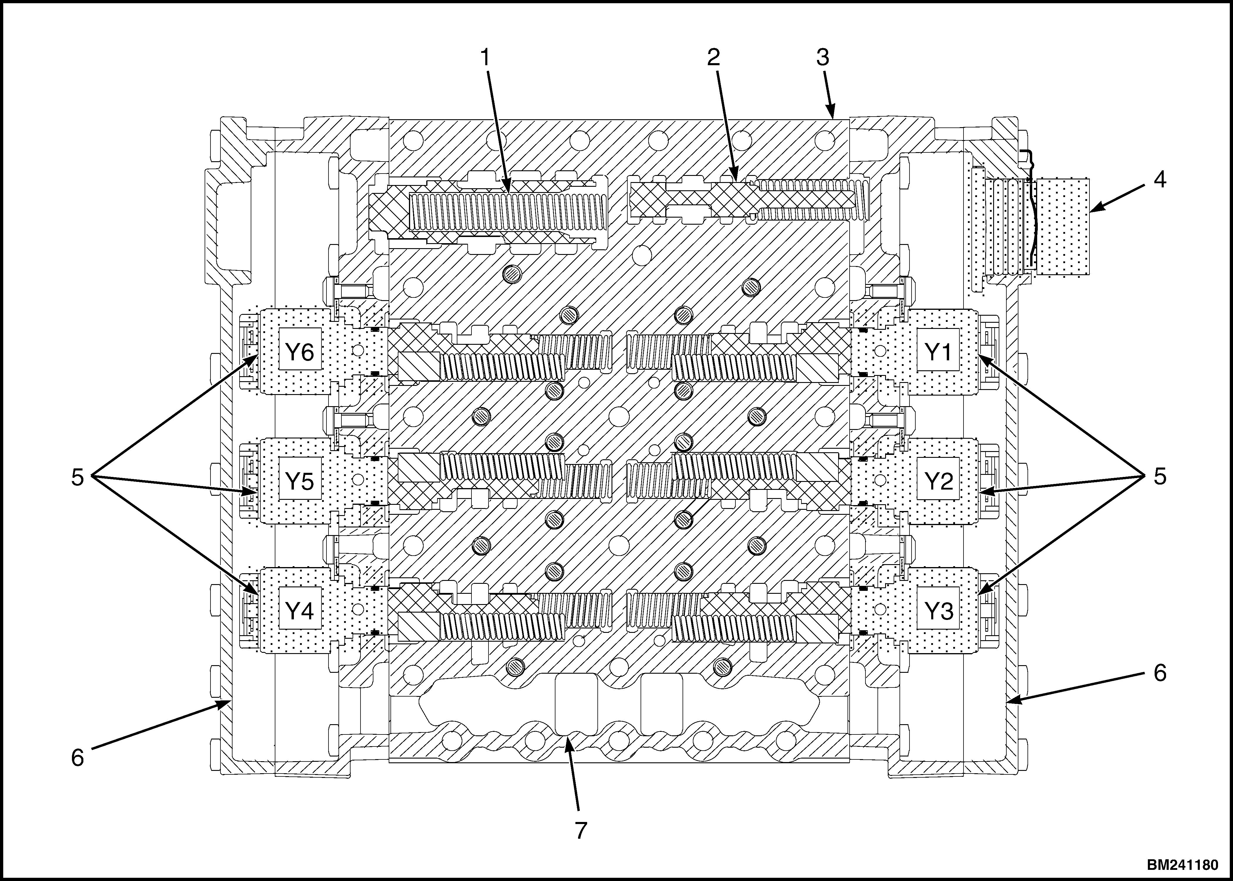
5.PRESSURE REGULATOR Y1 – NOT USED
6.PRESSURE REGULATOR Y2 – REVERSE
7.PRESSURE REGULATOR Y3 – FIRST
8.COVER
9.PRESSURE REGULATOR Y4 – THIRD
10.PRESSURE REGULATOR Y5 – FORWARD
11.PRESSURE REGULATOR Y6 – SECOND
Figure 7. Clutch Valve
Figure 8. Hydraulic Control Valve
COOLING AND LUBRICATION
Heat is primarily generated at the torque converter and at the clutch plates during transmission operation. The heat generated by mechanical friction at gears, shafts and bearings is relatively low.
Heat generated in the torque converter relates directly to the degree of stall, (i.e. the speed difference between engine and turbine). In a stall situation most of the supplied engine power is transferred into heat. This heat accumulates in the torque converter because of the reduced oil flow during a stall situation. With increasing turbine speed, the volume of added heat reduces, while simultaneously, the increased oil flow more rapidly transfers the accumulated heat.
Heat generated at the clutch plates varies with the available engine power at time of clutch engagement and the duration of clutch engagement. During normal operation, the transmission control system determines the duration of clutch engagement. During inching it is the driver who controls the added heat in the clutch by varying engine power and clutch engagement. The transmission control system will close the forward or reverse clutch when a certain amount of generated heat has been exceeded.
Oil flow for cooling and lubrication passes through the torque converter. To protect the torque converter and the oil cooler, the converter safety valve limits maximum pressure between 11 and 13 bar (159.6 and 188.5 psi). To prevent cavitation during stall situations, the pressure back up valve maintains a minimum pressure of about 2.5 bar (36 psi).
The maximum occuring pressure at the pressure back up valve shoulde never exceed 7.3 bar (106 psi).
From the transmission lubrication port the oil flows into channels in the different shafts, which lead to the shaft bearings for lubrication, and to the inside of the clutch packs where the oil absorbs the heat that is generated at the clutch plates. See Figure 9.
To expedite the warming up process, a thermostat valve is fitted between the torque converter outlet port and the transmission cooler. The thermostat starts opening at 70°C (158°F) and is completely opened at 85°C (185°F). At temperatures below 70°C (158°F), oil flow is directly returned to the transmission. At temperatures above 85°C (185°F), the entire oil flow from the outlet port has to pass the cooler before it is returned to the transmission.
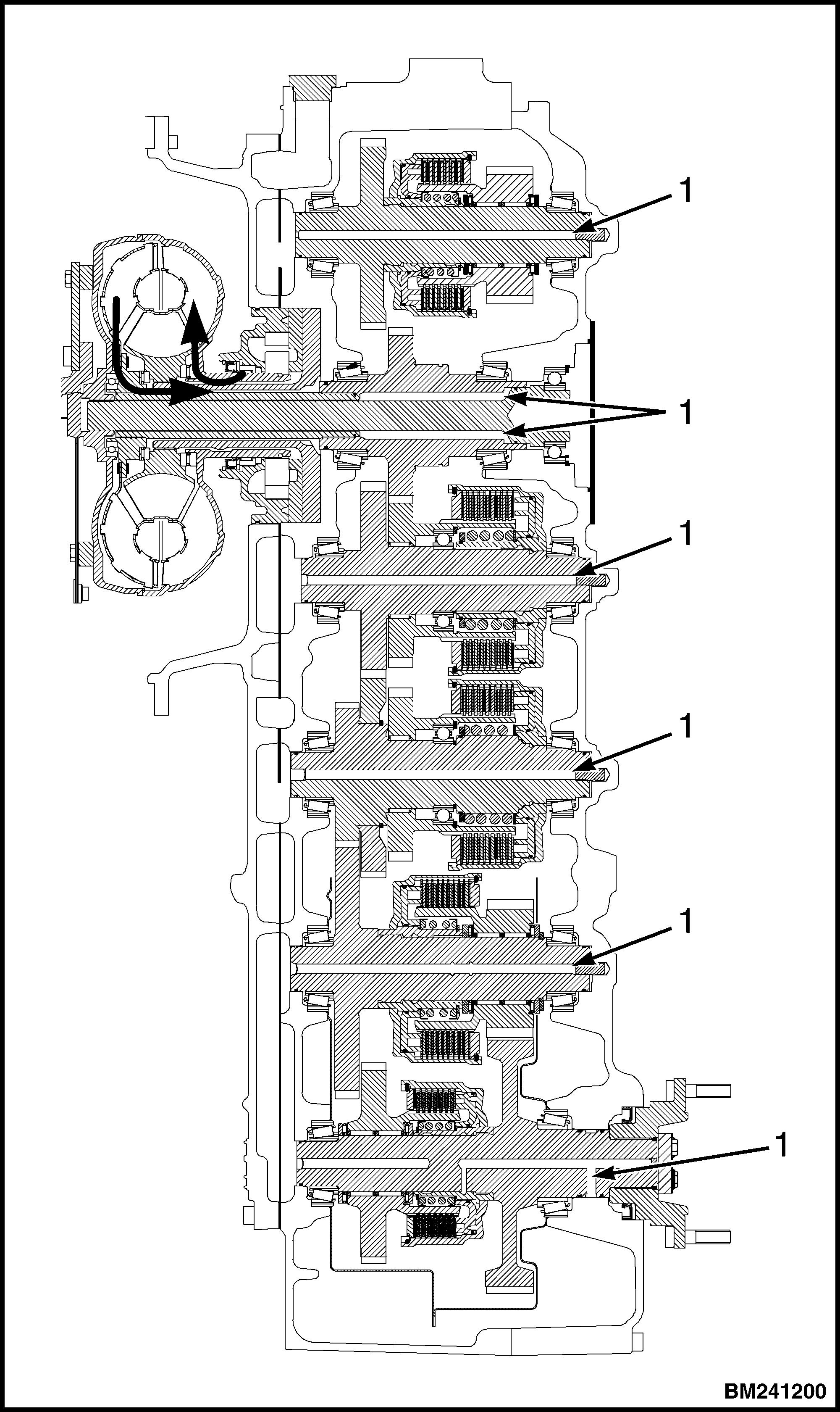
1.OIL CHANNEL
Figure 9. Cooling and Lubrication
CONTROL SYSTEM
The control system of the ZF Ergopower Transmission is based on inputs from different speed sensors to the Transmission Control Unit (TCU). The TCU reacts to these signals by changing its output signals to the pressure regulators for an adjusted clutch pressure. Input signals from other components such as the shift lever, parking brake or temperature sender, apply certain limitations to these output signals.
During shifting the following criteria will be considered:
• Speed of engine, turbine, central gear train and output.
•Transmission temperature.
• Shifting mode (up, down, reverse shifting, and speed engagement out of neutral).
• Load condition (full or part load, traction during shifting).
Transmission Control Unit (TCU)
The TCU has software to control the operation of the transmission and performs the following functions:
•Perform self-test and troubleshooting.
•Functional control of the transmission.
-Automatic shifting.
-Inching.
•Enter a protection mode when required.
- Improper pressures, temperatures, and speeds.
-No operator present.
-Parking brake applied.
- Gear or direction change at improper speeds.
• Logging a fault code when circumstances have exceeded certain values.
• Allow diagnostics and calibration with a laptop (Testman).
Depending on the signals of the shift lever and various switches and senders, the TCU activates or deactivates the pressure regulators in the control valve, which transfer hydraulic pressure to the clutches in the transmission. If an input signal does
not comply with the programming of the TCU, the TCU will record the fault and react by activating a protection mode. All events recorded are stored as a fault code and/or exceed code and are shown on the instrument cluster when the fault occurs. Faults can also be read at a later point in time, making it possible to trace intermittent problems.
Protection modes and self tests are part of the TCU programming and cannot be influenced.
The TCU is located in the side console of the cab. The gauges and displays on the dashboard are used to read transmission related information. For diagnostics and settings, it is more convenient to use a laptop loaded with the Testman software.
Operating Modes
Normal Mode
There is NO failure detected in the transmission system or the failure has little or no effect on transmission control. The TCU will perform with little or no limitations.
Substitute Clutch Control
The TCU CANNOT change the gears or the direction under the control of the normal clutch modulation. The TCU uses the substitute strategy for clutch control, all modulations are time controlled. The display will show t_SCC
Limp-Home Mode
The detected failure in the system has strong limitations to transmission control. The TCU will only be able to engage one gear in either direction. In some cases only one direction will be possible. The display will show t_LMP.
When the system enters the Limp-Home Mode, the controller shifts the transmission into neutral.
To continue driving, the operator must stop the truck, move the gear selector into the NEUTRAL position and then move the gear selector into travel mode. For trucks with a MONOTROL pedal, make a direction change by using this pedal.
CLICK HERE TO DOWNLOAD THE COMPLETE MANUAL
• Thank you very much for reading the preview of the manual.
• You can download the complete manual from: www.heydownloads.com by clicking the link below
• Please note: If there is no response to CLICKING the link, please download this PDF first and then click on it.
CLICK HERE TO DOWNLOAD THE
When truck speed in Limp-Home Mode exceeds a certain value, then the controller shifts into neutral again, requiring another full stop of the truck and another selector direction change.
Transmission Shut Down Mode
If there is a severe failure detected by the TCU, control of transmission will be disabled. The TCU will shut off the solenoid valves for the clutches and the common power supply (VPS1). The TCU will shift the transmission into NEUTRAL.
The operator must stop the truck. The transmission will remain in NEUTRAL
TCU Shut Down Mode
Occurs when the TCU has detected a severe failure that disables control of the system. The display will show t_SHT.
At this time the TCU will shut down all solenoid valves and both common power supplies (VPS1 and VPS2).
The transmission will stay in NEUTRAL.
Transmission Exceed Codes
During operation of the truck, the TCU controller may display transmission exceed codes on the LCD of the instrument cluster. These exceed codes reflect that the request made by the operator will not be executed because of certain circumstances. See the section Transmission Exceed Codes for a list of transmission exceed codes and a description of the encountered circumstances.
Self-Test
At power up a series of checks is performed. If the TCU fails these checks, it will shut off all outputs. The transmission cannot be operated until the problem is rectified. The relevant fault code will be displayed.
Fault Codes
Description
The LCD can show different modes:
•Hour Meter Mode
• Error Mode (only shown if there are active errors)
•Calibration Mode (special entry condition)
•Error Log Mode (special entry condition)
Under normal operating conditions the LCD will show only the hour meter. If there are active errors it will scroll between Hour and Error Mode.
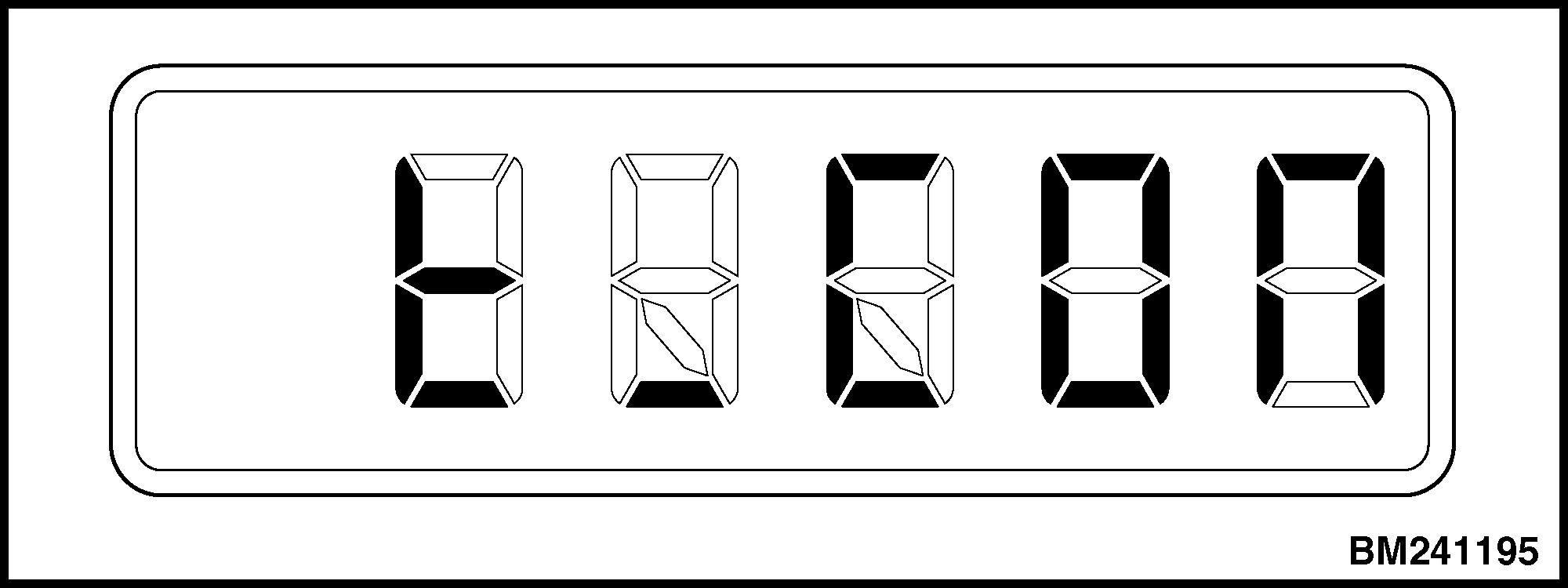
During TCU start-up the display will show te_NN It verifies if all conditions are met before it allows normal operation.
During start-up the LCD can show 1,2 or 3 if some quick ignition ON is done or diagnostic switch is pressed, this is part of the special entry condition sequence for Error mode.
•Hourmeter Reading
When the hourglass is shown, the LCD display is in hour meter mode and is showing engine running hours. See Figure 10.
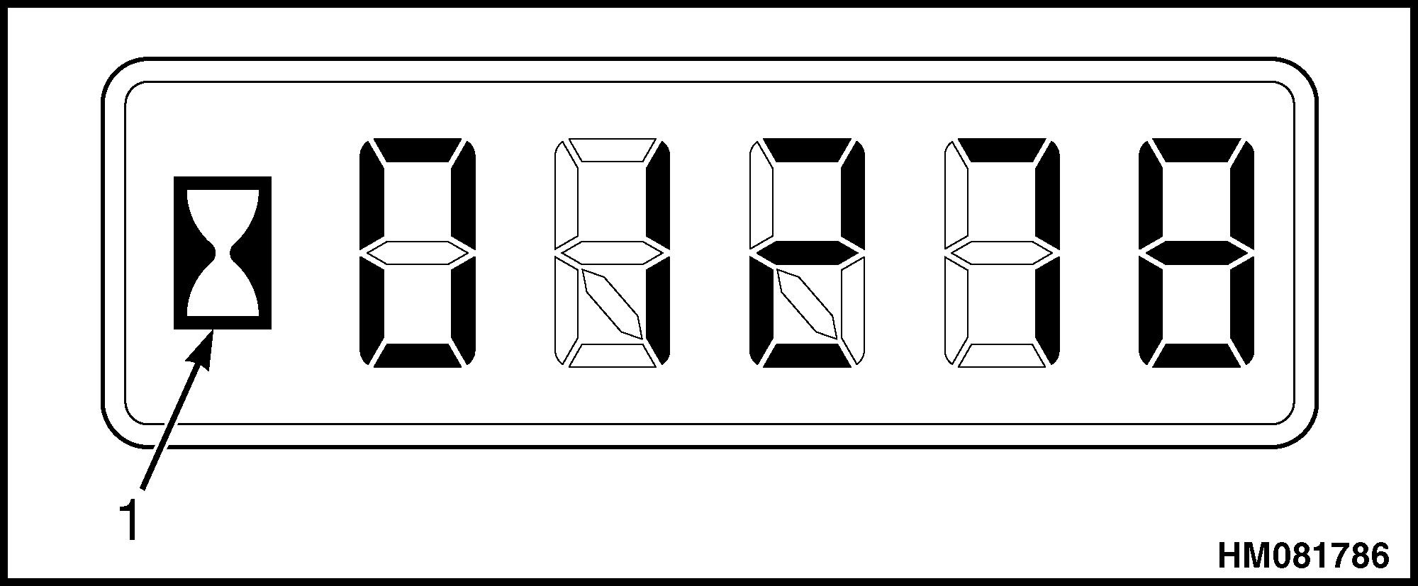
If the transmission controller detects a fault, the LCD will show a fault code instead of the engine running hours.
Fault codes starting with "t" refer to transmission exceed and fault codes. Refer to the section ZF Transmission Fault Codes in this manual for a list of exceed codes and fault codes.
When more than one fault occurs at the same time, the fault codes will be displayed in succession. When circumstances have changed, and all faults have ceased to exist, the hour meter/fault code display will show engine running hours again.
1.HOUR GLASS
Figure 10. Hourmeter Display
Fault code t_CON indicates a communication problem.
Fault code t_CON is shown when the instrument cluster does not receive a cyclic message or receives incorrect messages from the TCU.
Fault Log Mode
Access
The instrument cluster has a memory that records each fault when it occurs. These faults that have occurred can be reviewed at a later point in time by entering into the fault log mode. Proceed as follows to enter into the fault log mode:
1. Apply parking brake.
2. Turn ON ignition, but do not start lift truck.
3. Press service switch 3 times, press approximately for one second and release for one second (this represents one cycle). After the first cycle, the display will show a 1. After the second cycle, the display will show a 2. After the third cycle, the display will show a 3.
The display is now in fault log mode. When no faults have been recorded, the LCD display shows "clear." When faults have been recorded, the display shows a letter and 4 numbers for each fault code. For transmission fault codes, the letter is "t".
After the fault code, three further numbers are shown.
The numbers represent the following:
•Fault code
•Hourmeter reading at last occurrence
•Hourmeter reading at first occurrence
•Number of occurrences of current fault
Each number is shown for 3 seconds, after which the following number is shown. The faults will be shown in the opposite sequence of occurrence: The most recent fault first and the first occurred fault last. When all recorded fault codes have been shown, the display will continue to repeat these recorded fault codes until the user exists the fault log mode.
Exit
To exit the fault log mode, turn the ignition OFF and ON and leave ignition ON for more than 2 seconds. The cluster will return to normal mode when the parking brake is released or when the engine is started.
Clear
To clear the fault codes logged in the display, proceed as follows:
1. Access into the fault log mode. See Access.
2. Clear the fault log by pressing the service switch three more times (one second on, one second off). This is a repetition of the procedure to access the fault log mode. See Access.
If the data-erasing process is successful, the display will show ’clear’. If the data-erasing process is not successful, the display will show the fault codes in the memory, shown in the order by the time of the occurrence. To return to the normal mode, follow the procedure as described in Exit.
Fault Rectification
Fault codes are listed in the section ZF Transmission Fault Codes, which provides a description of the fault and the reaction of the TCU. Each fault code represents a specific error or malfunction.
In most cases the suggested rectification is by checking electrical functionality between the TCU, the wiring and the sensors, solenoids, or switches.
Before disassembling components for test purposes, connect the Testman software. The software allows verification of the functionality of speed sensors, contamination switch, temperature sensor, shift lever, inch sensor, solenoids and throttle sensor. In case several possible defects are indicated, the Testman software may narrow down the number of possible defects, preventing unnecessary removal of components that function correctly.
To rectify problems with switches, solenoids and sensors, look up their actual location, and test the component. For the location of the pressure regulators see Hydraulic Control Valve. For the location of sensors and switches see Speed and Temperature Sensors, and Figure 13. For test values of solenoids and sensors see Electrical Specifications.
NOTE: The Testman software and the Diagrams manual have wire and input references that relate to the TCU.
To determine the exact location of a harness problem, look up the reference number of the component involved in Diagrams SRM. The legend of Diagrams SRM shows the related connector code and wire harness.
Diagrams SRM shows the wire harnesses that are relevant for the TCU wiring. Actual location of the connectors can be derived from their position on the harness and from their description. At the legend of the wire harness figures, pin location figures are shown for connectors interconnecting between harnesses.
To identify the harness problem, first determine connectivity between the TCU and the connector of the component that was indicated in the ZF Transmission Fault Codes. If an unsatisfactory result is returned, measure connectivity from harness to harness.
HYDRAULIC CONTROL VALVE
The hydraulic control valve is located at the lefthand side of the transmission and contains the pressure regulator valves and check ports. Function of the hydraulic control valve depends on available pump supply pressure and the activation of the pressure regulators. Activation of the pressure regulators is controlled by the TCU. Hydraulic function of the control valve is schematically shown in Figure 6.
The location of the different pressure regulators are shown in Figure 11.
The location of the main components of the control valve are shown in Figure 12.
1.MAIN PRESSURE VALVE
2.PRESSURE REDUCING VALVE
3.HOUSING
4.CABLE HARNESS CONNECTOR
12. Control Valve Components
5.PRESSURE REGULATOR
6.COVER
7.VALVE BLOCK
Legend for Figure 12
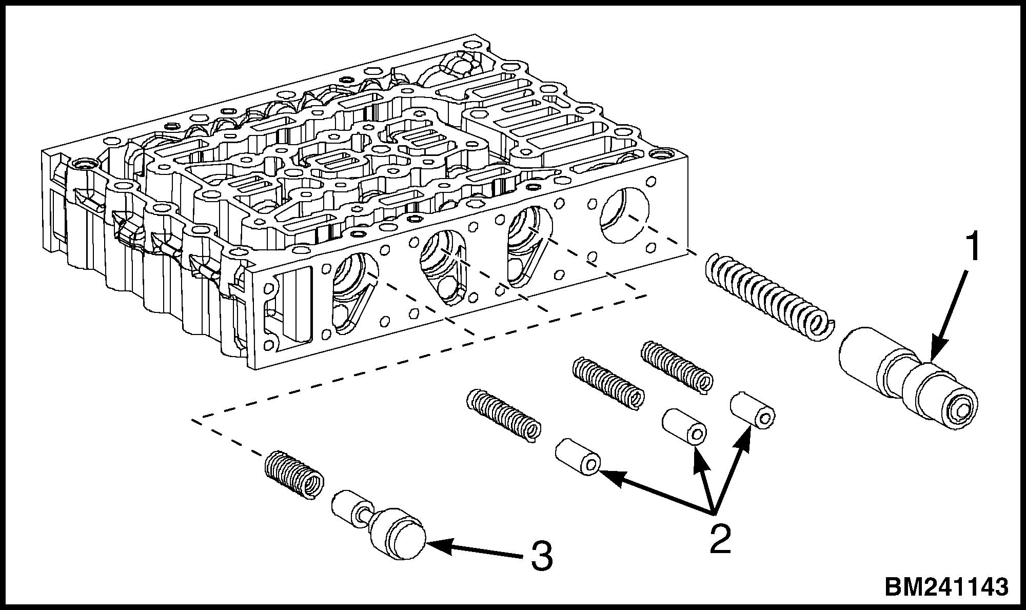
1.MAIN PRESSURE VALVE WITH SPRING
2.VIBRATION DAMPER WITH SPRING
3.FOLLOW-ON SLIDE WITH SPRING
Figure 11. Solenoid Locations
Figure
CLICK HERE TO DOWNLOAD THE COMPLETE MANUAL
• Thank you very much for reading the preview of the manual.
• You can download the complete manual from: www.heydownloads.com by clicking the link below
• Please note: If there is no response to CLICKING the link, please download this PDF first and then click on it.
CLICK HERE TO DOWNLOAD THE
Hydraulic Control Valve Repair
Repairs to the control valve, in most circumstances, are limited to replacing solenoids and gaskets. Hydraulic components of the control valve may be inspected, are available for replacement, but cannot be adjusted.
For details of control valve replacement see the manual Transmission Repair (ZF-WG161) 1300SRM1456.
Solenoid Replacement
For details of solenoid replacement see the manual Transmission Repair (ZF-WG161) 1300SRM1456.
Pressure Check
All transmission oil pressures can be measured at the side of the control valve by using M10X1 fitting. See Figure 13 and Table 1 for list of check port numbers and their description. The port numbers mentioned at each check point correspond with the port numbers as shown on Figure 6.
None of the oil pressures are adjustable. If a pressure is out of specification, the cause has to be established by further checking.
The control valve includes the main pressure valve and (pilot) pressure reducing valve.
The check ports for various clutches can be pressurized with air. The amount of air pressure applied should be approximately 14 bar (200 psi). When applying air pressure to the check ports, clutch engagement and obvious leaks can be established. For the location of the ports see Figure 13.
Pressure Specifications
Temperature of the oil must be 80 to 90°C (180 to 199°F) for correct pressure measurement.
In the cooling and lubrication circuit the torque converter causes additional flow resistance with increasing speed difference between engine and transmission input shaft.
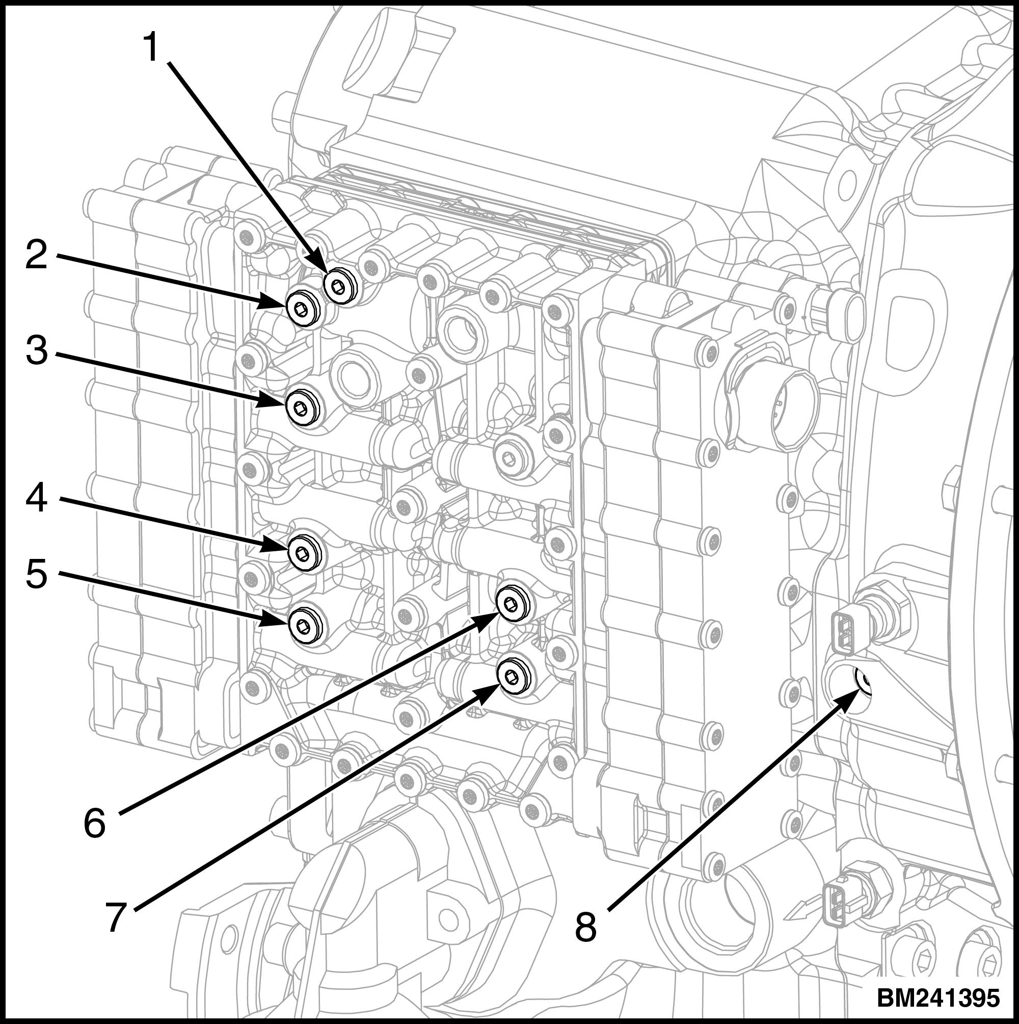
Figure 13. Check Ports, Control Valve
SPEED AND TEMPERATURE SENSORS
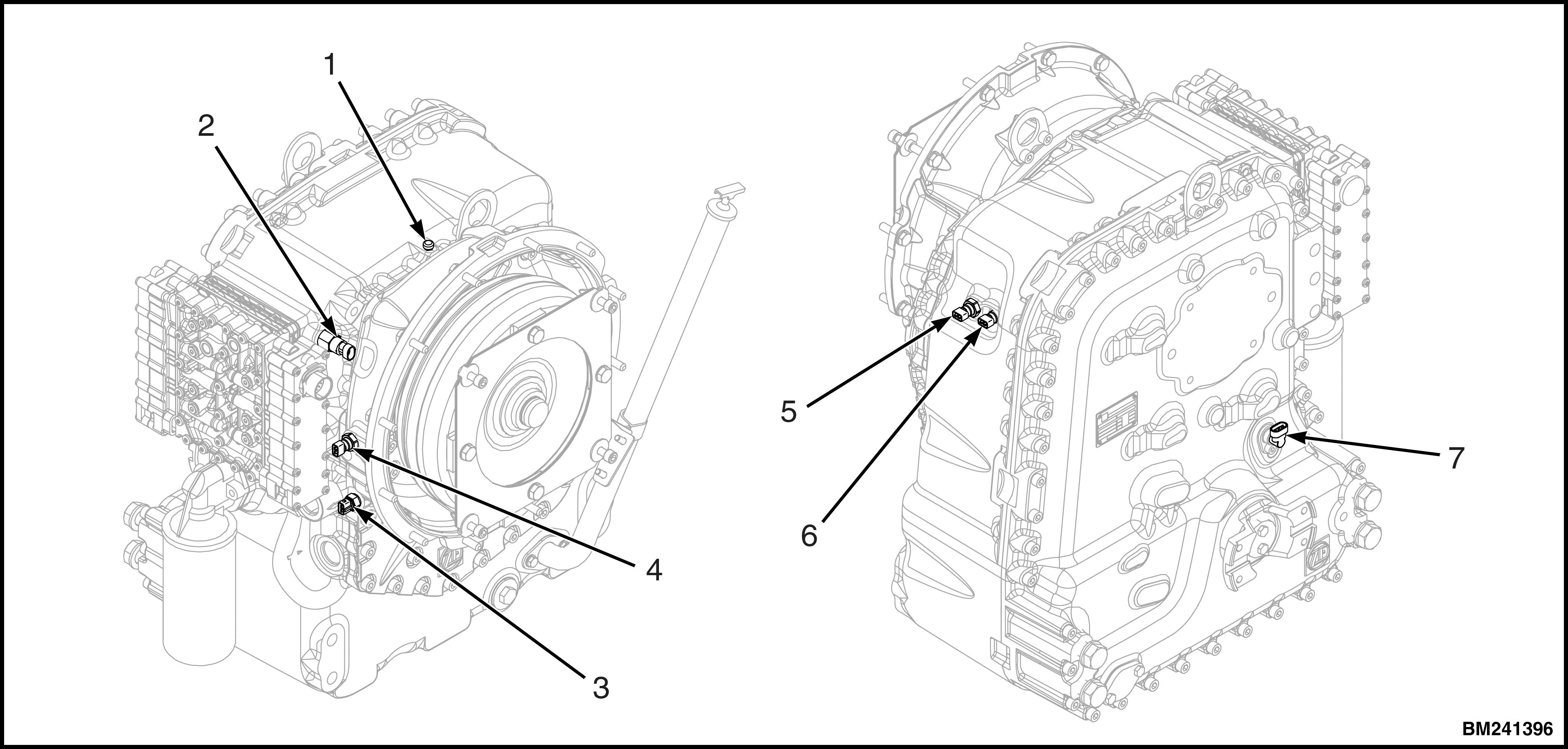
1.BREATHER
2.FILTER CONTAMINATION SWITCH
3.ENGINE SPEED SENSOR
4.CONVERTER OUTPUT TEMPERATURE SENSOR
5.INTERMEDIATE SPEED SENSOR
6.TURBINE SPEED SENSOR
7.OUTPUT SPEED SENSOR
Figure 14. Sensors and Switches
Before disassembling components for test purposes, connect the Testman software. The software allows verification of the functionality of several components, preventing unnecessary removal.
Speed Sensors
The function of the speed sensors is to determine the rotation speed of the different groups of gears. The TCU calculates the speed ratios between the different groups and compares the calculated values with the programmed values. If deviation exceeds an allowable value, the TCU generates a fault code and eventually enters a protection mode. See Figure 14. Below are a few examples of speed inputs and ratios that are monitored by the TCU:
•Converter Speed Ratio
- The ratio between engine speed and turbine speed is called the converter speed ratio, which is a measure of the
power being transferred through the converter. This ratio is a major factor for the TCU to determine in the automatic selection mode, if a next higher or lower gear is to be selected. During calibration, a sudden change in converter speed ratio is used to determine the clutch piston position, at the moment the clutch starts clamping.
•Transmission Ratio
- Each selected transmission gear has a specific transmission ratio. When one of the direction clutches is closed and the output speed has reached a certain value for checking, then the actual ratio is compared with the specified ratio. If deviation exceeds limits, one of the clutches is assumed to be slipping. A fault is flagged and the TCU enters the Shut Down Mode.
•Gear Ratio
-If the turbine, internal or output speed sensor fails, then the TCU calculates the actual ratio’ based on the value of the remaining sensors. This allows continued operation of the transmission. Speed sensor failure is indicated by a fault code. If the engine speed sensor fails, or if more than one speed sensor fails, then the TCU will enter the Limp Home Mode and flag a fault.
•Maximum Torque During Inching
- The TCU programming interprets the inching pedal position as the required pressure for the inching clutch. The heat generated in the inching clutch is proportional to the power transferred by the torque converter (= converter speed ratio). When the power transferred is at too high level during too long a time, the TCU will release pressure in the clutch and flag a fault.
Test
Testman shows functionality of each of the speed sensors under "Speeds/Torque Monitor". Electrical functionality can be tested by checking resistance over the sensors. See Electrical Specifications.
Temperature Sensors
There are two temperature sensors which measure the temperature at two different locations as follows:
•Sump Temperature (pump supply), Port 63
- This sensor is integrated in the control valve wiring harness and is connected with the TCU. The signal to the TCU is translated into a CANbus signal to the dashboard and represents transmission sump temperature. Testman indicates functionality of this sensor under Speeds/Torque Monitor’.
•Torque Converter Out, Port 52
- This sensor is connected with the TCU. The function is to trigger a protection mode. Testman indicates functionality of this sensor under "Speeds/ Torque Monitor".
Shift Lever
The shift lever is mounted on the left side of the steering column and provides information to the TCU. The direction of travel is selected by moving the lever from the middle neutral position to the up position to go forward or to the lower position to go in the reverse direction. To select the desired drive program, rotate the selector handle to the desired position 1 through 4. See Figure 15 and Table 2.
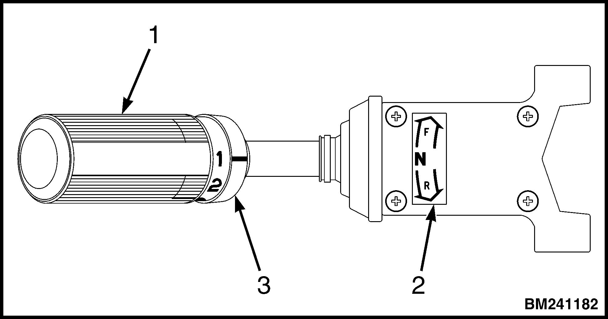
1.SELECTOR HANDLE
2.DIRECTION INDICATOR
3.DRIVE PROGRAM SELECTOR
Figure 15. Shift Lever
Table 2. Gear Selection
ShiftLeverPosition ShiftingRange
J007,H019,J019,andA238
Position 1 1st Gear
Position 2 2nd and 3rd Gear
Position 3 1st to 3rd Gear
B238,L007andK019
Position 1 1st Gear
Position 2 1st to 2nd Gear
Position 3 2nd and 3rd Gear
Position 4 1st to 3rd Gear
MONOTROL® Pedal
The MONOTROL® pedal controls the speed of the engine and the direction of travel. See Figure 16 There are two switches in the MONOTROL® pedal assembly. When the parking brake is released, the parking brake switch permits battery power to flow to the MONOTROL® pedal switches.
When the MONOTROL® pedal is in the forward position, the forward pedal switch is actuated. Battery power flows through the forward pedal switch to the TCU. When the MONOTROL® pedal is in the reverse position, the reverse pedal switch is activated. Battery power flows through the reverse pedal switch to the TCU. See Figure 16.

ZF TRANSMISSION TEST AND CALIBRATION
Transmission Test and Calibration
Precautions
Before testing or calibrating the transmission, verify the following:
• Make sure the coolant level in the engine cooling system is correct.
• Make sure the parking brake and service brakes operate correctly.
• Make sure the oil level in the transmission is at "Full Level" when hot.
• Make sure the transmission oil temperature is at least 71°C (160°F).
See the Operating Manual for instructions on how to add coolant and transmission oil.
Stall Test Description
The stall test provides indications for the condition of the engine, transmission clutches, and torque converter. The stall test is performed with the transmission engaged and operating the engine at full throttle while blocking the drive wheels. The stall speed should be between 1950 rpm and 2110 rpm.
Stall Test Procedure
CAUTION
Do not hold the throttle open for more than 15 seconds at a time. Permit the engine to operate at idle speed for two minutes between tests.
CAUTION
Release the accelerator immediately if the engine speed increases to its governed speed: Cummins Diesel Engine, 2425 rpm ±2%
CAUTION
Performing a stall test in 1st gear may damage the internal parts of the drive axle.
Perform the stall test in 2nd gear only (gear selector position 2).
1. Connect a laptop computer to the diagnostic connector in the side console. Select the screen (Speeds/Torque Monitor) to read the engine speed.
2. Put a capacity load on the forks to prevent the wheels from turning.
3. Put the lift truck against an object that cannot move.
4. Select 2nd gear forward by moving the gear selector forward in position 2.
5. Push the accelerator pedal to full throttle.
6. Read the engine (stall) speed and release the throttle pedal.
Figure 16. MONOTROL® Pedal
If the stall speed is 50 to 200 rpm below the specification, the engine is not operating at full power. Check if engine fault codes are present and rectify any indicated problems.
If the stall speed is higher than specification, the engaged clutch(es) may not be holding or the torque converter is damaged. Check if transmission fault codes are present and rectify any indicated problems.
If no transmission fault codes are present and the stall speed is much higher than specification, remove the torque converter for inspection or replacement.
If stall speed is only slightly higher than specification, consider service life of the torque converter and the option to replace the torque converter immediately or at a later point in time.
Inch Pedal Calibration
Description
Inching is a controlled traction and braking mode. It enables higher engine speeds for increased hydraulic function speeds, while truck travel speed remains low. The inching function is obtained by relating the inching pedal position to clutch pressure. This relation results in a natural reaction of the operator to depress the inch pedal further when actual truck speed is too high. Further depressing the inch pedal increases service brake pressure and also causes pressure to drop in the inching clutch, which reduces truck speed independent of engine speed.
For correct inching operation the controller needs to have the exact sensor tension values entered for the inch pedal positions “completely released” and “completely depressed”. The controller assumes that the pedal position “completely released” will correspond with a value between 0.7 and 0.9 Volt and the position “completely depressed” will correspond with a value between 4.3 and 4.7 volt. The actual resistance values are entered during the cal-
ibration procedure. The controller generates a fault code when the actual value falls outside of the accepted range.
Inch pedal calibration is required when a new controller is installed, or when inching sensor adjustment has been changed. If the inch pedal is not calibrated, the truck will not move and a fault code is shown on the LCD display.
NOTE: Apart from the inching signal itself, the inching sensor generates a second signal which is 50% lower than the inching signal. The purpose is to monitor correct functionality and avoid uncontrolled pressurization of the inching clutch. If these two signals are out of range, the LCD display will show fault code tP421, demanding replacement of the inching sensor.
Calibration
Before calibrating the inch pedal, the brake and inch pedal, and the inching sensor must be adjusted. See Inch Sensor Adjustment.
Brake and Inch Pedal Adjustment
1. Turn the adjustment bolt for the brake pedal until there is no play between the bolt on the brake valve and the roller under the brake pedal. See Figure 17.
2. Position the top of the inching pedal and the brake pedal at equal height. Adjust the adjustment bolt for the brake pedal coupling so that the inching pedal has no free play.
Inch Sensor Adjustment
1. Connect a laptop, loaded with Testman software, to the diagnostic connector located in the side console. See Figure 18.
2. Select Analog Inputs in Testman.
3. Verify Inch Sensor 1 (AU1 [V]) voltage for the inching sensor is between 0.8-0.9V (800-900 mV).
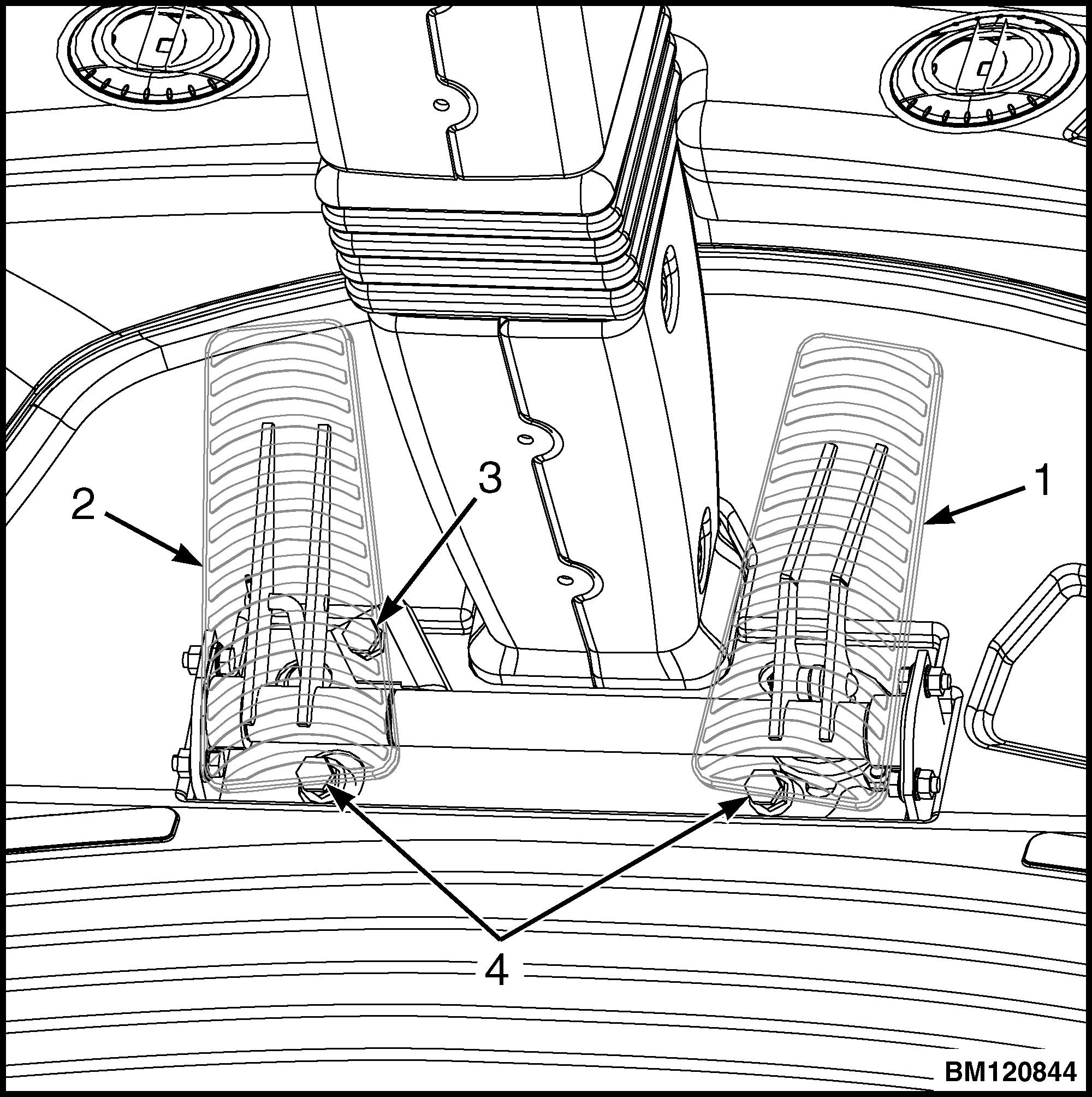
1.BRAKE PEDAL
2.INCHING PEDAL
3.PEDAL COUPLING ADJUSTMENT BOLT
4.PEDAL ADJUSTMENT BOLT
Figure 17. Pedal Assembly
4. If voltage is incorrect, proceed as follows:
a. Raise the Cab until the latch locks in the partial open position. See Operator's Cab 0100SRM1390 for proper procedure.
b. Loosen the two mounting bolts of the inching sensor.
c. Rotate the sensor in the slotted holes until output voltage is between 0.8-0.9V (800-900 mV) in released pedal position.
d. Tighten the two mounting bolts and verify output voltage is still correct.
Inch Pedal Calibration
Preparation
1. Park truck on level ground and apply the park brake.
2. Make sure pedals and inch sensor have been correctly adjusted.
3. Verify the Forward/Reverse lever is in NEUTRAL. 4. Turn the ignition key in the OFF position.
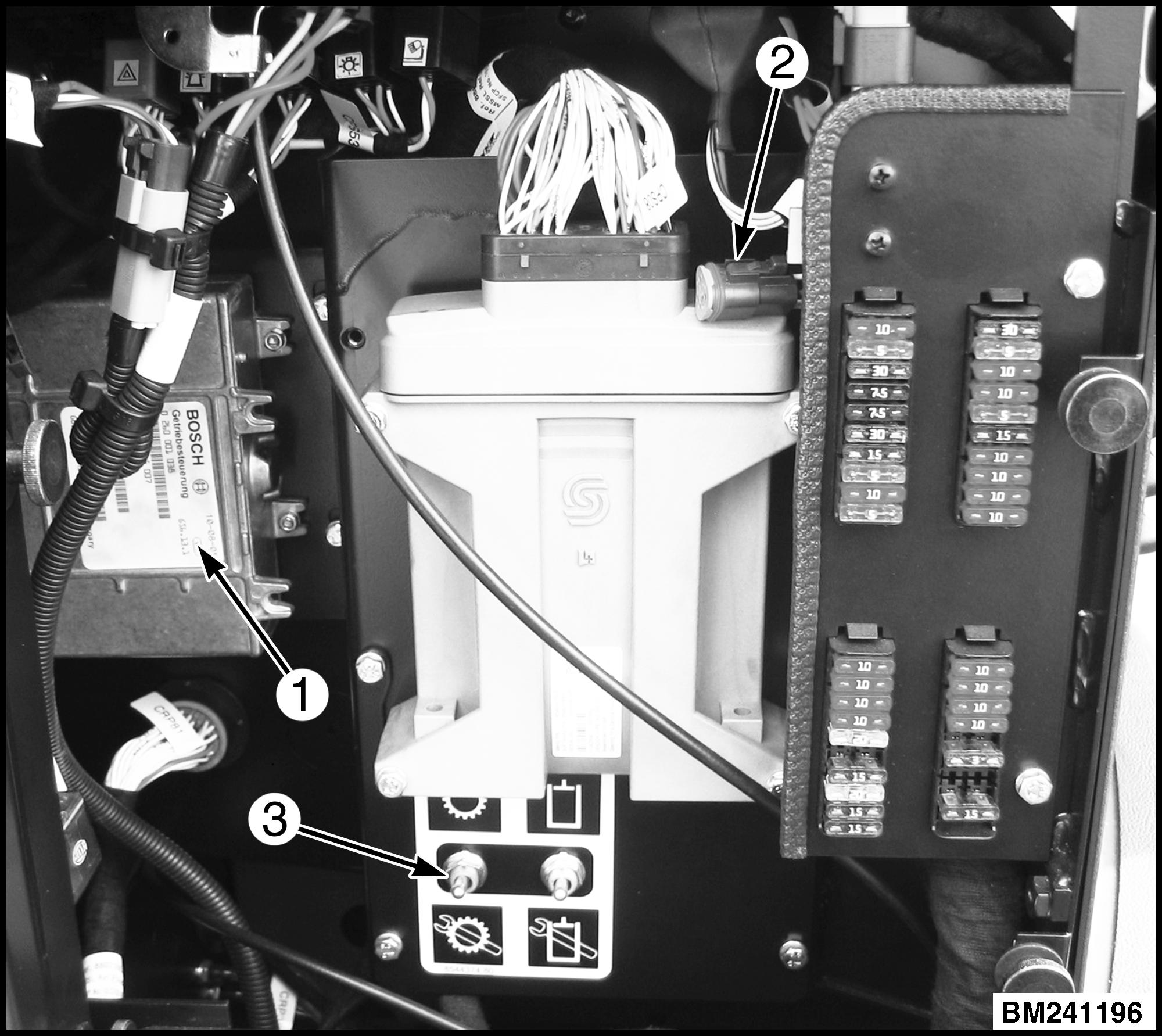
1.TCU
2.DIAGNOSTIC CONNECTOR
3.CALIBRATION SWITCH
Figure 18. Calibration Switch Location
Calibration Procedure Using the Calibration Switch
1. Turn the calibration switch to the ON position (flip the switch to the down position) and sit in the operator’s seat. See Figure 18.
2. Turn the ignition key switch to the ON position, but DO NOT start the truck. The inch pedal calibration mode is now active.
3. The LCD display shows: tP_dn. Slowly press the inch pedal all the way down to the end position in 2 to 3 seconds and hold.
4. The LCD display shows: tP_UP. Slowly release the inch pedal in 2 to 3 seconds to the completely released position.
5. When all values are within range the LCD display shows: tPSEt, indicating inch pedal calibration is finished.
6. If inch pedal calibration is not successful, the LCD display shows a fault code. See Inch Pedal Calibration Fault Codes.
CLICK HERE TO DOWNLOAD THE COMPLETE MANUAL
• Thank you very much for reading the preview of the manual.
• You can download the complete manual from: www.heydownloads.com by clicking the link below
• Please note: If there is no response to CLICKING the link, please download this PDF first and then click on it.
CLICK HERE TO DOWNLOAD THE