
3 WG-94 EC
TECHNICALDATA
DESCRIPTION
OPERATION
MAINTENANCE
DIAGNOSTICSYSTEMS
ZF Passau GmbH Donaustr. 25 - 71
D - 94034 Passau Subject to technical modifications!
CLICK HERE TO DOWNLOAD THE COMPLETE MANUAL
• Thank you very much for reading the preview of the manual.
• You can download the complete manual from: www.heydownloads.com by clicking the link below

• Please note: If there is no response to CLICKING the link, please download this PDF first and then click on it.
CLICK HERE TO DOWNLOAD THE
1st Edition: 11/2007
Preface
This documentation has been developed for specialized staff trained by ZF Passau for repair and maintenance work to be made on ZF units. Due to the continuous technical upgrading of the product, however, the repair and maintenance of the unit at your disposal may require both deviating work steps and differing setting and testing data.
This manual is based on the state-of-the-art at the time of printing. It was prepared with utmost care in order to avoid errors. However, we shall not be liable for any possible errors in figures or descriptions.
We reserve the right to make modifications without prior notice.
The owner and the user shall be responsible for complying with the safety instructions and for implementing the maintenance work according to the specified guidelines.
ZF shall not be liable for any incorrect installation, improper handling, insufficient maintenance, improperly or incompetently performed work and any consequential damage resulting thereof.
It is imperative to observe the relevant instructions and manuals of the vehicle manufacturer.
Important information regarding technical reliability and operational safety are highlighted by the following symbols:
This is applicable for instructions to be observed for maintenance, operation or handling of the vehicle!
Refers to working and operating processes which must be strictly observed to avoid any damage to or destruction of the unit or to exclude any endangerment to persons!
I. DESCRIPTION
1.1 Operating mode of the converter
1.2 Powershift transmission
1.3 Transmission control
1.4 Controller DW-3
1.5 Electronic control unit TCU
1.6 Electronic controls for ZF powershift transmissions
1.6.1 General
1.6.2 Description of basic functions
1.6.3 AEB (=Automatic Determination of Filling Parameters=ADFP)
1.6.4 Electrical inching
1.7 Description of the fault codes for ERGO-Control EST-65
1.7.1 Abbreviations
1.7.2 Display
1.7.3 Possible Indications on the Display during operation
1.7.4 Possible Indications on the Display during AEB-Mode
1.7.5 Possible Indications on the Display during Inchpedal Calibration
1.7.6 Definition of operating modes
3.4 Transmission control in "Automatic" driving range 3.5 Stopping and parking 3.6 Towing 3.7 Oil temperature
4.1 Oil grade 4.2 Oil level check
4.3 Oil and filter change intervals
4.3.1 Oil change and oil fill quantity
4.3.2 Filter change
V.
CLICK HERE TO DOWNLOAD THE COMPLETE MANUAL
• Thank you very much for reading the preview of the manual.
• You can download the complete manual from: www.heydownloads.com by clicking the link below
• Please note: If there is no response to CLICKING the link, please download this PDF first and then click on it.
CLICK HERE TO DOWNLOAD THE
TECHNICALDATA
Engine power:
Turbine torque:
Engine speed:
Stall torque ratio:
Engine-dependent PTOs:
KW*
Nm*
Mass (without oil):
* = depending on vehicle type and application ** = depending on transmission version
Description:
The ZF transmissions 3 WG-94 EC are composed of a hydrodynamic torque converter and a rear-mounted multi-speed powershift transmission with integrated transfer box (see table 1). The torque converter is a wear-free start-up device which, due to its continuously variable design, adapts itself to the required situations (necessary input torque).
Input by direct mount via flexplate to the engine, or remote mount (input via U-joint shaft) with DIN, Mechanics or Spicer input flange.
The transmission can be shifted manually or fully automatically by means of the electronic control unit EST-65 (24 volts).
Torque converter:
Size W 280 with torque multiplication
Powershift transmission: 3 forward gears and 3 reverse gears
Output:
The powershift transmission has a center distance of 306 mm between input and output shaft and can be equipped with output flanges towards the rear axle for various U-joint shafts.
PTO:
For driving an external oil pressure pump, the system incorporates an engine-dependent, coaxial PTO which can optionally be supplied in disconnectible version. This PTO allows the attachment of pumps with SAE-C connection.
LABELING OF IDENTIFICATION PLATE FOR ZF-POWERSHIFT TRANSMISSIONS
1 = Transmission type
2 = Transmission number
3 = ZF parts list number
4 = Overall transmission ratio
5 = Oil filling (oil specification)
6 = ZF List of Lubricants
7 = Oil fill quantity
8 = Customer number
INFORMATION ON SPARE PARTS ORDERING:
Please indicate the following information when ordering genuine ZF spare parts:
1. = Transmission type
2. = Unit number
3. = ZF parts list number
4. = Make and type of spare part
5. = Denomination of spare part
6. = Spare part number
7. = Shipping mode
You will find this information on the identification plate!
Please indicate all the a.m. details to avoid any mistakes in the delivery of the ordered spare parts!
IMPORTANT INSTRUCTIONS
Oil level check (see 4.2):
In the cold-start phase, the engine must be running at idling speed for about 2 –3 min. and the marking on the oil dipstick must then be above the cold-start level. The oil level check in the transmission must be carried out at engine idling speed and operating temperature of the transmission ( 80° to 90° C ).
At shut-off engine, the oil level in the transmission is rising essentially, depending on the installation conditions !
The ZF filter must be replaced at every oil change. In addition, ZF recommends to start the automatic calibration of the shifting elements (AEB).
The automatic calibration of shifting elements (AEB) must be started by the vehicle manufacturer after initial installation of transmission and electronic system into the vehicle, and after every replacement of transmission and TCU in case of a failure.
On vehicles with electronic inching, also the IPK (Inch Pedal Calibration - Inch Sensor Calibration) should be initiated after each AEB start.
When starting the engine, always place the gear selector into neutral position. At running engine and transmission in neutral, make sure that the parking brake has been engaged or the service brake has been actuated, in order to prevent the vehicle from rolling away.
Loosen the parking brake prior to every start-off.
Engagement of the gear from neutral is only possible under the programmed transmission input speed (turbine speed).
Gear selector in neutral position is not allowed at increased vehicle speeds (above walking speed). Promptly engage a suitable gear, or slow down the vehicle immediately.
When the engine is shut off, there is no power flow between transmission and engine in spite of a preselected speed on the gear selector, that means the transmission is in idling position. Therefore, the parking brake must be fully actuated! When leaving the vehicle, secure it additionally by wheel chocks!
In any case, the towing speed must not exceed 10 km/h and the towing distance must not be longer than 10 km.
It is imperative to observe this instruction, since otherwise the transmission will be damaged due to insufficient oil supply!
For longer-distance transport of the defective vehicle we recommend to use a flatbed truck.
Operating temperature after the converter 65° C min. and 100° C in continuous operation; short-term increase up to 120° C max. is permitted.
In case of irregularities on the transmission put the vehicle out of service and ask for specialists.
Protective measures for the ZF electronic system during electrical work on the vehicle:
At the following operations, the ignition must be shut off and the control unit plug must be pulled off the ZF electronic system:
∗
during any kind of electrical operations on the vehicle
∗ during welding operations on the vehicle
∗
during insulation tests on the electric system
CLICK HERE TO DOWNLOAD THE COMPLETE MANUAL
• Thank you very much for reading the preview of the manual.
• You can download the complete manual from: www.heydownloads.com by clicking the link below
• Please note: If there is no response to CLICKING the link, please download this PDF first and then click on it.
CLICK HERE TO DOWNLOAD THE
I. DESCRIPTION
1.1 Operating mode of the converter:
Operating mode of a hydrodynamic torque converter (schematic view)
TP =torqueofpump wheel
TT =torqueof turbinewheel
TR=torqueof reactionmember (stator)
from the engine
starting condition
intermediate condition
condition shortly before the converter clutch is closed
towards the transmission
at standstill
FigureNo.:1.1
The converter operates according to the Trilok system. This means at high turbine speed it assumes the characteristics and thus the favorable efficiency of a fluid clutch.
The converter is designed according to the engine power so that the most favorable operating conditions are obtained for each installation case.
The torque converter consists of 3 main parts:
Pump wheel – turbine wheel – stator (reaction member)
The circular arrangement of these 3 impellers allows the fluid to flow through the circuit components in the indicated order.
Pressure oil from the transmission pump is constantly streaming through the converter, thus allowing the converter to fulfill its task of multiplying the engine torque. At the same time, the heat produced in the converter is dissipated via the dispersed oil.
The oil which is streaming out of the pump wheel enters the turbine wheel and is there reversed in its direction of flow.
Depending on the rate of reversal, a more or less high reaction torque is applied to the turbine wheel and thus to the output shaft.
The stator (reaction member) following the turbine has the task to reverse the oil streaming out of the turbine once more and to deliver it to the pump wheel under the suitable discharge direction.
Due to the reversal, a reaction torque is applied to the stator.
The relation turbine torque/pump torque is called torque multiplication. Its level depends on the extent of speed difference between pump and turbine wheel.
Therefore, the max. torque multiplication is generated at stationary turbine wheel.
The torque multiplication decreases with increasing output speed.
Matching of the output speed to a certain required output torque is achieved by the torque converter in a continuously variable and automatic way.
When the turbine speed reaches about 80% of the pump speed, the torque multiplication becomes 1.0, i.e. the turbine torque gets equal to the pump torque.
From this point on, the converter is working similar to a fluid clutch.
A stator freewheel serves to improve the efficiency in the upper driving range. It is backing up the torque upon the housing in the torque multiplication range, and is released in the clutch range.
In this way, the stator can rotate freely.
1.2 Powershift transmission:
The multi-speed reversing transmission in countershaft design is powershiftable by hydraulically actuated multi-disk clutches.
All gears are in constant mesh and carried on antifriction bearings.
The gears, bearings and clutches are cooled and lubricated with oil.
The 3-speed reversing transmission is equipped with 5 multi-disk clutches.
In shifting operation, the respective disk package is compressed by a piston which is movable in axial direction and pressurized by pressure oil.
A compression spring pushes the piston of clutches KV, KR, KD, and KE back and thus releases the disk package.
A cup spring package pushes the piston of clutch KC back
For the transmission configuration and information on the closed clutches in the different gears please refer to Table 1 and 4.
1.3 Transmission control:
Transmission control see measuring points and oil circuit diagram Table 4 and 5.
The transmission pump which is necessary for the oil supply of the converter and for the transmission control is located within the transmission on the engine-dependent input shaft.
The pump feed rate is Q = 45 l /min, at nengine= 1 500 min -1 .
This pump is sucking the oil out of the oil sump via the coarse filter, and delivers it to the main pressure valve via the ZF filter.
ZF filter:
Filtration ratio acc. to ISO 4572: ß30 ≥ 20 ß10 ≥ 1.5
min. filter surface: 2780 cm2
min. dust capacity acc. to ISO 4572 : 19 g
ZF coarse filter (screen):
Mesh size: 0.800 mm
The 5 clutches of the transmission are controlled via the 4 proportional valves Y1 to Y5
The direct proportional control with separate pressure modulation for each clutch controls the pressures towards the clutches which are involved in the gear change.
This allows a hydraulic overlapping of the clutches to be engaged and disengaged. The pressure modulation to the respective clutch is controlled by cup springs and proportional valves in the clutch package.
This creates spontaneous shiftings without tractive effort interruption.
The following criteria are considered during the shifting operation:
- RPM of engine, turbine, gear chain and output
- Transmission temperature
- Shifting mode (upshifting, downshifting, reverse shifting and gear engagement out of neutral)
- Load condition (full and partial load, drive, coast, including consideration of load reversals during shifting)
- Electronic inching
The main pressure valve limits the max. control pressure to 16+3 bar and releases the main stream towards the converter- and lubrication circuit.
The converter inlet incorporates a converter safety valve which protects the converter from high internal pressures (opening pressure 11+2 bar)
Within the converter, the oil serves for transmitting the power according to the well-known hydrodynamic principle (see Chapter torque converter 1.1).
To avoid cavitation, the converter must always be completely filled with oil.
The oil coming out of the converter is directed to a heat exchanger.
The selection and determination of the heat exchanger must be carried out by the customer on his own responsibility, according to our Installation Guidelines for Hydrodynamic Powershift Transmissions.
The heat exchanger is not included in the delivery scope of ZF Passau GmbH.
From the heat exchanger, the oil is directed to the transmission and the lubricating oil circuit, so that all lubricating points are supplied with cooled oil.
CLICK HERE TO DOWNLOAD THE COMPLETE MANUAL
• Thank you very much for reading the preview of the manual.
• You can download the complete manual from: www.heydownloads.com by clicking the link below
• Please note: If there is no response to CLICKING the link, please download this PDF first and then click on it.
CLICK HERE TO DOWNLOAD THE
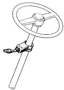
1.4 Controller DW-3
- see Table-7
The Controller is designed for the mounting on the steering column left side. By a rotative motion, the positions (speeds) 1 to 4 are selected by tilting the lever, the driving direction (Forward (F) – Neutral (N ) – Reverse (R).
The DW-3 Controller is also available with integrated Kickdown pushbutton.
For the protection from unintended start off, a Neutral interlock is installed: Position „N“ – Controller lever blocked in this position Position „D“ – Driving
1.5 Electronic control unit TCU
The electro-hydraulic transmission control is governed by connection to the electronic TCU.
The basic functions of the automatic system are the automatic shifting of gears, matching of the optimum shifting points as well as comprehensive safety functions regarding operating errors and overloadings of the power-transmitting components with an extensive fault memory.
The control units allow a wide spectrum of customer- and vehicle-specific programming. Control parameters can be logically linked, and special functions such as gear limitation and converter functions can be integrated.
Due to the great number of available TCUs, the exact technical data are to be taken from the respective installation drawing.
The installation of the TCU is optional. Preferably, ZF recommends the version shown in Figure No. 1.5 B1.
The TCU is to be installed in a protected place in the driver's cab.
A flooding with water must be excluded. Furthermore, the entry of water via the plug connection must be prevented by appropriate measures on the wiring harness.
TCU installation position
TCU installation dimensions
1.6 Electronic controls for ZF powershift transmissions
1.6.1
General
Due to the different configurations of electronic transmission controls within the various vehicles, please refer to the Operating Instructions of the vehicle manufacturer or to the Technical Data Sheet of the parts list versions involved. These also include the relating wiring diagram (see example in Table 8). On request, this information can also be obtained from ZF-Passau.
Depending on the vehicle type, the wiring will be implemented according to the cable routing plans.
The corresponding electric circuit diagrams (proposals) will be issued by ZF.
Upon request, the wiring can also be supplied by ZF.
If the wiring is implemented by the vehicle manufacturer, it must comply with the ZF requirements (see Installation Guidelines).
1.6.2
Description of basic functions
The powershift transmission 3 WG-94 EC of series WG-90 is equipped with the electronic transmission control EST-65 specially developed for this purpose.
The system processes the driver command according to the following criteria:
• Gear determination depending on driving speed and load condition
• If required, protection against operating errors is possible via electronic protection (programming)
• Protection against overspeeding (on the basis of engine and turbine speed)
• Pressure cut-off possible (vehicle-specific, only after coordination with ZF)
• Switch-over possibility for automatic / manual operation
• Downshifting functions possible
• Electronic inching
Legend to Figure No. 1.6.2
1 = Inching pedal (option)
2 = Gear selector (option)
3 = Display (option)
4 = Acoustical / optical warning (option)
5 = Switch for driving program Manual/Automatic (option)
6 = CAN connection
7 = TCU
8 = Diagnostic Laptop with ZF diagnostic system Testman/Pro
9 = Inductive sensor - speed of central gear chain
10 = Speed sensor - output
11 = Temperature measuring point after the converter „No. 63“
12 = Inductive sensor - turbine speed
13 = Inductive sensor – engine speed
14 = Temperature measuring point for the converter „No. 64“
15 = Proportional valve Y3 - KC clutch
16 = Proportional valve Y2 - KR clutch
17 = Proportional valve Y1 - KV clutch
18 = Proportional valve Y5 - KE clutch
19 = Proportional valve Y4 - KD clutch
17 = Ergopower transmission 3 WG-94 EC
Overall system of EST-65


The EST-65 system reactions in case of error described in Table-9 are for information only. As to the binding description and procedure for correcting the errors indicated on the vehicle fault code display please refer to the operating instructions of the vehicle manufacturer.
1.6.3 Automatic calibration of shifting elements (AEB)
The AEB compensates tolerances (disk clearance and pressure level) which are influencing the filling procedure of the clutches. For each clutch, the correct filling parameters for
* duration of fast-filling time
* level of filling compensation pressure are determined within a test cycle.
The filling parameters are stored in the transmission electronics, together with the AEB program and the driving program.
Since the electronic system is supplied separately, the AEB cycle must not be started until both components have been installed into the vehicle, in order to ensure the correct pairing (transmission and electronics).
In any case, the AEB cycle must be carried out at the vehicle manufacturer prior to shipment of the vehicles.
It is imperative to observe the following testing conditions:
• "Neutral" shift position
• engine in idling speed
• parking brake actuated
• transmission at operating temperature
After replacement of the transmission or the TCU within the vehicle, the AEB cycle must be restarted.
The AEB cycle takes approx. 3 to 4 minutes. The determined filling parameters are stored in the EEProm of the electronic system. This also deletes the fault message F6 shown on the display in case of non-performed AEB.
There are two basic possibilities for starting the AEB cycle:
1. AEB start by separate tools which are connected to the diagnostic port of the wiring.
The ZF Service Department offers the following tools for AEB start:
- Testman/Pro (see item 5.3 - diagnostic systems)
- AEB starter
Order No.: 0501 211 778
Just for starting the AEB, you can use the special tool developed by ZF for that purpose (see Figure No. 1.6.3)!
2. AEB start by operating elements on the vehicle. This requires a CAN communication between transmission and vehicle electronics.
When the transmission is operated, the paper friction linings installed in the Ergopower transmissions are setting, i.e. the disk clearance increases. Since these setting phenomena may affect the shifting quality, ZF recommends to repeat the AEB cycle at the maintenance intervals (see 4.3.1).
If the shifting quality deteriorates, ZF also recommends to repeat the AEB cycle as a first measure.
IPK (Inch Pedal Calibration - Inch Sensor Calibration) shall also be carried out after each AEB start (see 1.7.5).
1.6.4 Electrical inching
This function is especially suitable for lift trucks. Without modifying the engine speed, it allows a continuously variable reduction of the driving speed to such a level that operation at a very low speed is possible. In this way, the driver can move the vehicle to a certain position with high accuracy.
At the same time, a large part of the engine power is available for driving the hydraulic lifting system, due to the high engine speed.
The electrical inching is operated via a separate inching pedal fitted with an angle-of-rotation sensor.
By means of the proportional valve technology, the TCU controls the pressure in the driving direction clutch in such a way that the driving speed is adjusted in accordance with the position of the inching angle-of-rotation sensor. Clutch overloading is prevented by the electronic protection.
After each readjustment of the inching linkage, the IPK (Inch Pedal Calibration - Inch Sensor Calibration) must be carried out.
During the inching calibration mode, the position of the inching pedal in neutral position and at full actuation is determined by the calibration process and stored in the TCU.
The inching function does not become active until successful completion of AEB and IPK start.
1.7 Description of the fault codes for ERGO-Control EST-65
1.7.1 Abbreviations
o.c. open circuit
s.c. short circuit
OP-Mode operating mode
TCU transmission control unit
EEC electronic engine controller
PTO power take off
CLICK HERE TO DOWNLOAD THE COMPLETE MANUAL
• Thank you very much for reading the preview of the manual.
• You can download the complete manual from: www.heydownloads.com by clicking the link below
• Please note: If there is no response to CLICKING the link, please download this PDF first and then click on it.
CLICK HERE TO DOWNLOAD THE
1.7.2 ZF - Display:
If a fault is detected, the display shows a spanner symbol (g) for a fault. The display shows the fault code, if the gear selector is on neutral position.
If more than one fault is detected, each fault code is shown for about 1 second.
Special symbols a - h
1.7.3 Display during operation
Symbol meaning
1F,1R
2F,2R
3F,3R
4F
5F
6F
LF,LR
actualgearanddirection
leftdigitshowsactualgear rightdigitshowsactualdirection
limphomegear
ForR,nogear ClutchCutoff
ForRflashing directionForRselectedwhileturbine speedistoohigh
NN notneutral,waitingforneutralafter poweruporaseverefault
remarks
CAUTION gearwillengageifturbinespeed drops
toengageagear,firstmoveshiftselectorto neutralposition andagaintoForRposition
** oiltemperaturetoolow,nogear available warmupengine/transmission
*N oiltemperaturelow,onlyonegear available warmupengine/transmission
1bar(special symbol) manualmode1stgear
Symbol meaning remarks
2bars manualmode2nd gear
3bars manualmode3rd gear
4bars manualmode4th gearandalso5th and 6th gearin6WG
4barsand2 arrows automaticmode
Barsflashing 6WG:converterlockupclutchopen 4WG:Downshiftmodeactiv differenceofengineandturbinespeedabovea certainlimitandlockupclutchnotactivated
Spanner atleastonefaultactiv selectneutraltogetfaultcodedisplayed
Faultcode seefaultcodelist
WS warningsumptemperature changesbetweenactualgear/directionwhile driving,inneutralonlydisplayedifnofaultis detected(spanner)
WR warningretardertemperature changesbetweenactualgear/directionwhile driving,inneutralonlydisplayedifnofaultis detected(spanner)
WT warningtorqueconvertertemperature changesbetweenactualgear/directionwhile driving,inneutralonlydisplayedifnofaultis detected(spanner)
WE warninghighenginespeed changesbetweenactualgear/directionwhile driving,inneutralonlydisplayedifnofaultis detected(spanner)
WV warninghighoutputspeed(velocity) changesbetweenactualgear/directionwhile driving,inneutralonlydisplayedifnofaultis detected(spanner)
WL warninghightransmissioninputtorque (load) changesbetweenactualgear/directionwhile driving,inneutralonlydisplayedifnofaultis detected(spanner)
WO warninghightransmissionoutputtorque (load) changesbetweenactualgear/directionwhile driving,inneutralonlydisplayedifnofaultis detected(spanner)
PN direction ForRselectedwhileparking brakeengaged transmissioninneutraluntilparkingbrakeis released
CAUTION:vehiclestartstomoveafterrelease ofparkingbrake
EEflashing nocommunicationwithdisplay checkedwiringfromTCUtodisplay
1.7.4 Display during AEB-Mode:
PL AEB-Starterispluggedatthe diagnosticplug
CLICK HERE TO DOWNLOAD THE COMPLETE MANUAL
• Thank you very much for reading the preview of the manual.
• You can download the complete manual from: www.heydownloads.com by clicking the link below
• Please note: If there is no response to CLICKING the link, please download this PDF first and then click on it.
CLICK HERE TO DOWNLOAD THE
Symbol meaning remarks
KA…..KE
KV,KR CalibratingclutchKA..KE,KVorKR resp.
_andKx waitforstart,initializationofclutchKx, x:1,2,3,4,V,R
≡ andKx fastfilltimedeterminationofclutchKx =andKx compensatingpressuredeterminationof clutchKx
OK calibrationforallclutchesfinished
STOP AEBcanceled(activationstopped)
STOPandKx AEBstopped,clutchKxcan'tbe calibrated
SpannerandKx Kxcouldn'tbecalibrated,AEBfinished
∆ E enginespeedtoolow, raiseenginespeed
∇ E enginespeedtoohigh, lowerenginespeed
∆ T transmissionoiltemperaturetoolow, heatuptransmission
∇ T transmissionoiltemperaturetoohigh cooldowntransmission
FT transmissiontemperaturenotindefined rangeduringcalibration
FB operatingmodenotNORMALor transmissiontemperaturesensor defectiveorstoringofCalibratedvalues toEEPROM-hasfailed.
FO Outputspeed_not_zero
FN Shiftlevernotin Neutralposition
FP Parkbrake_not_applied
STOP AEB-Starterwasusedincorrectoris defective.Wrongdeviceorwrongcable used
1.7.5 Display during Inchpedal Calibration:
IP ⇓ pushdownthepedalslowlyuntil endpositionisreachedandholdthis position
IP ⇑
Releasethepedalslowlyuntil endpositionisreached
IP blinkt Aproblemoccurred,releasethepedal slowlyuntilendpositionisreached
OK Finishedinchpedalcalibration successful
KA,KBfor2geartransmission
KC,KD,KEfor3geartransmission
Transmissionsstaysinneutral,youhaveto restarttheTCU(ignitionoff/on)afterremoving AEB-Starter
Transmissionsstaysinneutral,youhaveto restarttheTCU(ignitionoff/on)
Transmissionsstaysinneutral,youhaveto restarttheTCU(ignitionoff/on)
Transmissionsstaysinneutral,youhaveto restarttheTCU(ignitionoff/on)
Transmissionsstaysinneutral,youhaveto restarttheTCU(ignitionoff/on)
Transmissionsstaysinneutral,youhaveto restarttheTCU(ignitionoff/on)
Transmissionsstaysinneutral,youhaveto restarttheTCU(ignitionoff/on)
Transmissionsstaysinneutral,youhaveto restarttheTCU(ignitionoff/on)
Transmissionsstaysinneutral,youhaveto restarttheTCU(ignitionoff/on)
Transmissionsstaysinneutral,youhaveto restarttheTCU(ignitionoff/on)
Iftheexpectedenpositioncouldnotbereached, releasethepedalandtryagain
Symbol meaning remarks
FNandStop Shiftlevernotin Neutralposition
FSandStop sensorsupplyvoltageAU1isoutofthe specifiedrange
FOandStop Outputspeedisnotzero
SLandStop sensorvoltagebelowspecifiedrangel
SUandStop sensorvoltageabovespecifiedrangel
ILandStop sensorpositionforreleasedpedaloutof specifiedrange
IUandStop sensorpositionforpressedpedaloutof specifiedrange
TOandStop time-outcalibration,pedalnotmoved aftercalibrationstart
DLandStop anglebetweenpedalpositionsreleased andpressedtosmall
DUandStop anglebetweenpedalpositionsreleased andpressedtobig
FIandStop sensorsignal1and2don'tmatch together
1.7.6 Definition of operating modes: NORMAL:
Calibrationisaborted
Calibrationisaborted
Calibrationisaborted
Calibrationisaborted
Calibrationisaborted
Calibrationisaborted
Calibrationisaborted
Calibrationisaborted
Calibrationisaborted
Calibrationisaborted
Calibrationisaborted
There's no failure detected in the transmission-system or the failure has no or slight effects on transmission control. TCU will work without or in special cases with little limitations. (see following table)
SUBSTITUTE CLUTCH CONTROL:
TCU can't change the gears or the direction under the control of the normal clutch modulation. TCU uses the substitute strategy for clutch control. All modulations are only time controlled.
LIMP-HOME:
The detected failure in the system has strong limitations to transmission control. TCU can engage only one gear in each direction. In some cases only one direction will be possible. TCU will shift the transmission into neutral at the first occurrence of the failure. First, the operator must shift the gear selector into neutral position.
If output speed is less than a threshold for neutral to gear and the operator shifts the gear selector into forward or reverse, the TCU will select the limp-home gear .
If output speed is less than a threshold for reversal speed and TCU has changed into the limphome gear and the operator selects a shuttle shift, TCU will shift immediately into the limphome gear of the selected direction.
If output speed is greater than the threshold, TCU will shift the transmission into neutral. The operator has to slow down the vehicle and must shift the gear selector into neutral position.
TRANSMISSION-SHUTDOWN:
TCU has detected a severe failure that disables control of the transmission.
TCU will shut off the solenoid valves for the clutches and also the common power supply (VPS1). Transmission shifts to Neutral. The park brake will operate normally, also the other functions which use ADM 1 to ADM 8.
The operator has to slow down the vehicle. The transmission will stay in neutral.
TCU-SHUTDOWN:
TCU has detected a severe failure that disables control of system.
TCU will shut off all solenoid valves and also both common power supplies (VPS1, VPS2). The park brake will engage, also all functions are disabled which use ADM 1 to ADM 8. The transmission will stay in neutral.