DOWNLOAD PDF Pages 001 150 Massey Ferguson MF 5400 Tractor Repair & Parts Manual
Introduction - Specifications
01- Introduction - Specifications
CONTENTS
1A10-Using the manual
1B10-SPECIFICATIONS- General specifications
1B11-SPECIFICATIONS- Forward speeds
1B12-SPECIFICATIONS- Dimensions
1B13-SPECIFICATIONS- Capacities
1C10-Miscellaneous
Massey Ferguson
CLICK HERE TO DOWNLOAD THE COMPLETE MANUAL
• Thank you very much for reading the preview of the manual.
• You can download the complete manual from: www.heydownloads.com by clicking the link below
• Please note: If there is no response to CLICKING the link, please download this PDF first and then click on it.
CLICK HERE TO DOWNLOAD THE
Introduction - Specifications
Massey Ferguson
1A10 - Using the manual
CONTENTS
A.General
B.Structure of
C.Service tools.
D.Repairs and parts replacement.
Massey Ferguson 5400
A . General
The purpose of this manual is to assist Dealers and Agents in the efficient installation, maintenance and repair of AGCO equipment. Carrying out the procedures as detailed, together with the use of special tools where appropriate, will enable the operations to be completed within the time stated in the repair time schedule.
B . Structure of the manual
Page numbering
This manual is divided into chapters and sections, each page containing the following information:
Example: 10A12.1
10 = chapter
A12 = section
1 = page number within the section
The issue number is indicated at the bottom of the page.
Summaries
For quick reference, each chapter starts with a table of contents, listing the various sections included in that chapter.
Meaning of references
(...): identification of parts and components
Amendments
Modified pages will be edited using the same page numbering as the preceding pages—only the issue number changes.
The old pages should be destroyed.
C . Service tools
Where the use of a service tool is necessary to carry out an operation, the tool reference is mentioned with the relevant instruction.
Tool drawings for locally made tools are given at the end of the relevant sections.
D . Repairs and parts replacement
When parts have to be replaced, it is essential that only genuine AGCO parts are used.
The following points are of particular importance when carrying out repairs and fitting replacement parts and accessories.
Tractor safety may be compromised if non-genuine parts are fitted.
Legislation in certain countries prohibits the fitting of parts that do not comply with the tractor manufacturer’s specifications. Torque wrench setting figures given in the workshop manual must be strictly adhered to. Locking devices must be fitted where specified. If the efficiency of a locking device is impaired during removal, it must be replaced.
The tractor warranty may be invalidated if non-genuine AGCO parts are fitted. All AGCO spare parts are guaranteed by the manufacturer. AGCO Dealers and Agents are required to supply genuine service parts only.
StabilisersTelescopic / without Multi-hole drawbarOptions
3-point linkageCat. 2, hook or ball type (*)
Clevis hitchStandard or assisted
Automatic clevis hitchStandard or assisted
Semi-mounted trailer hitch Stud (*)
Swinging drawbarStandard
Roller type swinging drawbar Options
Power take-off
TypeInterchangeable shaft
540/1000/ecoOptional (*)
Number of clutch discs5
PTO brakeHydraulics
Front axle
ModelDANA AG 130 (735/524)
Type
Fixed
Rotational direction Clockwise Clutch Multidisc
Factor K 1.376
Swivelling mudguard (4WD) Options 2WD Options
Hydraulics
Open Centre 57 l/min Standard
Open Centre 100 l/min Options
Orbitrol steering 160 cc
Brake master cylinder Standard
Braking assistance Options
Trailer brake Optional (*)
Auxiliary spool valves 0 - 4 mechanical Couplers
Electronics
Decompression
Transmission control AUTOTRONIC5
Linkage controller AUTOTRONIC5
Draft sensors 1
Sensor capacity 4 T
Datatronic Without Fieldstar Options Cab
Rear-view mirrors Standard / Telescopic (optional)
Air conditioning Manual Cab Orchard
Reference (*): according to country
CLICK HERE TO DOWNLOAD THE COMPLETE MANUAL
• Thank you very much for reading the preview of the manual.
• You can download the complete manual from: www.heydownloads.com by clicking the link below
• Please note: If there is no response to CLICKING the link, please download this PDF first and then click on it.
CLICK HERE TO DOWNLOAD THE
SPECIFICATIONS- Forward speeds
1B11 - SPECIFICATIONS- Forward speeds
CONTENTS
A.Speedshift models.
B.Dyna4 models
Massey Ferguson
A . Speedshift models
5425/5435 Speedshift models
Road speeds at 2200 rpm, 16.9R34 tyres
2 C 2.953.730.740.930.210.272.873.620.720.910.210.26
4 C 5.927.481.481.870.420.535.747.261.441.810.410.52 D 7.489.451.872.360.530.687.269.171.812.290.520.66
1 C 7.849.91----7.619.61---D 9.9112.53----9.6112.15---2 C 11.8514.97----11.4914.52---D 14.9718.92----14.5218.36---3 C 16.3920.72----15.9020.10---D 20.7226.72----20.1025.40----
4 C 23.7330.00----23.0229.10---D 30.0037.91----29.1036.77----
SPECIFICATIONS- Forward speeds
5445 Speedshift models
Road speeds at 2200 rpm, 16.9R38 tyres
7.9710.071.992.520.560.717.739.771.932.440.550.68
9.8712.47----9.5712.10----
11.7914.90----11.4414.46----
14.9018.84----14.4618.27---3 C 17.4622.07----16.9421.40---D 22.0727.89----21.4027.05---4 C 23.6329.86----22.9228.96---D 29.8637.74----28.9636.61----
5455/5460 Speedshift models
Road speeds at 2200 rpm, 18.4R38 tyres DIRECTION
1 C 2.182.760.550.690.160.202.122.680.530.670.150.19 D 2.763.490.690.870.200.252.683.380.670.850.190.24 2 C 3.304.170.821.040.240.303.204.040.801.010.230.29 D 4.175.271.041.320.300.384.045.111.011.280.290.37 3 C 4.886.171.221.540.350.444.745.981.181.500.340.43 D 6.177.801.541.950.440.565.987.561.501.890.430.54
4 C 6.618.351.652.090.470.606.418.101.602.020.460.58 D 8.3510.552.092.640.600.758.1010.242.022.560.580.73
1 C 8.1810.34----7.9410.03---D 10.3413.07----10.0312.68---2 C 12.3615.62----11.9915.15---D 15.6219.74----15.1519.15---3 C 18.3023.12----17.7522.43---D 23.1229.23----22.4328.35----
4 C 24.7631.29----24.0230.35---D 31.2939.55----30.3538.36----
C 8.1810.34----7.9410.03---D 10.3413.07----10.0312.68---2 C 12.3615.62----11.9915.15---D 15.6219.74----15.1519.15---3 C 18.3023.12----17.7522.43---D 23.1229.23----22.4328.35---4 C 24.7631.29----24.0230.35---D 31.2939.55----30.3538.36----
5460 SA (Orchard) Speedshift models
Road speeds at 2200 rpm, 18.4R30 tyres
SA (Orchard)
B . Dyna4 models
Road speeds at 2200 rpm, 18.4R34 tyres
NOTE: -1/4 creeper gears cannot be engaged with ranges 3 and 4. -Maximum speed is limited by the electronic transmission control.
CLICK HERE TO DOWNLOAD THE COMPLETE MANUAL
• Thank you very much for reading the preview of the manual.
• You can download the complete manual from: www.heydownloads.com by clicking the link below
• Please note: If there is no response to CLICKING the link, please download this PDF first and then click on it.
CLICK HERE TO DOWNLOAD THE
5465/5470
Dyna 4 models
Road speeds at 2200 rpm, 18.4R34 tyres
-1/4 creeper gears cannot be engaged with ranges 3 and 4.
-Maximum speed is limited by the electronic transmission control.
-1/4 creeper gears cannot be engaged with ranges 3 and 4. -Maximum speed is limited by the electronic transmission control. 5460 SA (Orchard) Dyna 4 models Road speeds at 2200 rpm, 18.4R30 tyres
5470/5475 SA (Orchard) Dyna 4 models
Road speeds at 2200 rpm, 18.4R30 tyres
-1/4 creeper gears cannot be engaged with ranges 3 and 4.
-Maximum speed is limited by the electronic transmission control.
1B12 - SPECIFICATIONS- Dimensions
CONTENTS
A.General dimensions and attachment points for Speedshift models . . .
B.General dimensions and attachment points for Dyna4 models. .
C.Adjusting track widths .
. . 3
8
Massey Ferguson 5400
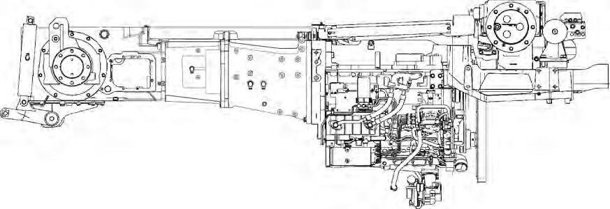
A . General dimensions and attachment points for Speedshift models
5425, 5435, 5445 and 5455 Speedshift
Fig. 2
MA-01-03224A
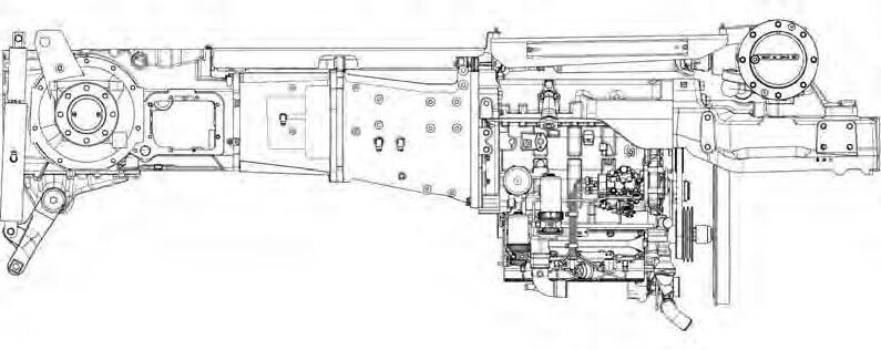
5465 Speedshift
MA-01-03224A
SPECIFICATIONS- Dimensions
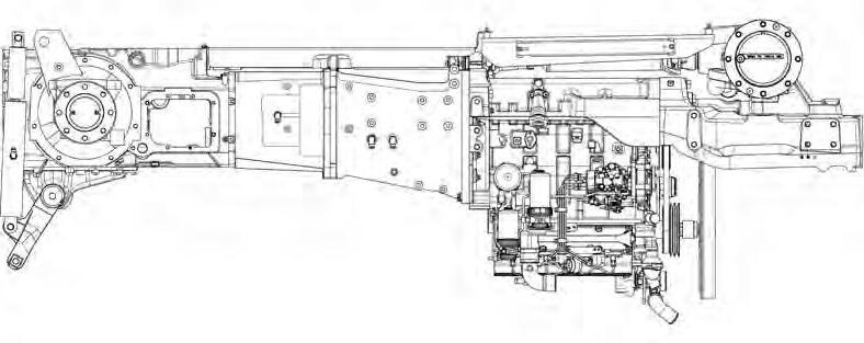
5460 SA Speedshift (Orchard)
4
Fig.
CLICK HERE TO DOWNLOAD THE COMPLETE MANUAL
• Thank you very much for reading the preview of the manual.
• You can download the complete manual from: www.heydownloads.com by clicking the link below
• Please note: If there is no response to CLICKING the link, please download this PDF first and then click on it.
CLICK HERE TO DOWNLOAD THE
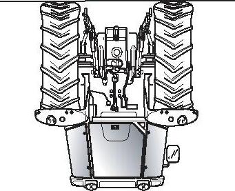
5470/5475 SA Speedshift (Orchard)
Fig. 5
SPECIFICATIONS- Dimensions
B . General dimensions and attachment points for Dyna4 models
NOTE: Distance in mm measured between tyre centres.
NOTE: If the wheels are to be inverted, be sure to swap the left and right-hand wheels in order to maintain their direction of rotation.
Rear track widths
Rims with welded steel discs
Assembly with rim offset turned inwards (Fig.12)
Without spacer (A) 1622
With 1 spacer (B) 1708
Assembly with rim offset turned outwards (Fig.12)
Without spacer (C) 1952
With 1 spacer (D) 2038
Spacer width 43mm / spacer
Wheel attachment 8-hole flange, Ø 203.2
Rim offset 75mm, disc thickness 15mm
SPECIFICATIONS- Dimensions
Rims with steel disc and lugs Rim size30"34"38" Assembly with rim disc turned inwards (Fig.13)
Assembly with rim disc turned outwards (Fig.13)
CLICK HERE TO DOWNLOAD THE COMPLETE MANUAL
• Thank you very much for reading the preview of the manual.
• You can download the complete manual from: www.heydownloads.com by clicking the link below
• Please note: If there is no response to CLICKING the link, please download this PDF first and then click on it.
CLICK HERE TO DOWNLOAD THE
SPECIFICATIONS- Dimensions
Front track widths
Rims with steel disc and 4 double lugs (Fig.14)
Rim dimensionWidth between flangesABCDEFGH
W7 x 24"166914921601152116301692180117211830
180016231732165217611823193218521961
W14 x 24"166914061515160717161606171518071916
180015371646173818471737184619382047
W12 x 28"166913081419150116121708181919012012
180014391550163217431839195020322143
Rims with steel disc and 6 single lugs (Fig.14)
Rim dimensionWidth between flangesABCDEFGH 24" or 28"166914361549164117541604171717891922
180015671680177218851735184819202053
Slotted rims with steel disc (Fig.14)
Rim dimensionWidth between flangesABCDEFGH
DWW13 x 30 W10 x 34 166913051406150716081711181219132014
180014361537163817391842194320442145
Wheel attachment 8-hole flange Ø 275
Rims with welded steel disc (Fig.15)
Rim dimensionWidth between flangesAB
W12 x 28
W15 x 28 1669 16191743 1800 17501874
W14 x 28 1669 16231739 1800 17541870
W10 x 24
W12 x 24 1669 16091749 1800 17401880
W14 x 24 1669 16091753 1800 17401884
Wheel attachment 8-hole flange Ø 275
SPECIFICATIONS- Dimensions
MA-01-03012A
Fig. 15
1B13 - SPECIFICATIONS- Capacities
CONTENTS
A.Capacities: GBA20 Speedshift models.
B.Capacities: GBA25 Dyna4 models.
SPECIFICATIONS- Capacities
Massey Ferguson
SPECIFICATIONS- Capacities
B . Capacities: GBA25 Dyna4 models
1C10 - Miscellaneous
CONTENTS
A.Conversion tables
B.Retaining compounds and sealing products.
Massey Ferguson 5400
A . Conversion tables
LENGTH
multiply by
mmx 0.0394in
inx 25.400mm
mx 3.2808ft
ftx 0.3048m
km x 0.6214mile
milex 1.6093 km
SURFACE AREA
multiply by
mm²x 0.0016 in²
in² x 645.16mm²
m²x 10.7639 ft²
ft² x 0.0929 m²
ha x 2.4711acre
acrex 0.4047 ha
VOLUME
multiply by
cm3 x 0.06102 in3
in3 x 16.387 cm3
m3 x 35.315 ft3
ft3 x 0.0283 m3
CAPACITY
multiply by
ml x 0.0352fl oz (UK)
fl oz (UK)x 28.4131 ml
ml x 0.0338fl oz (US)
fl oz (US)x 29.5735 ml
l x 0.2200gal (UK)
gal (UK)x 4.5640 l
l x 0.2640gal (US)
gal (US)x 3.7850 l
gal (UK)x 1.2010gal (US)
gal (US)x 0.8330gal (UK)
POWER
multiply by
hp x 0.9863bhp (UK)
bhp (UK)x 1.0139 hp
kW x 1.3410bhp (UK)
bhp (UK)x 0.7457 kW
kW x 1.36 hp
hp x 0.736 kW
TORQUE
multiply by Nm x 0.7375lbf ft
lbf ft x 1.356 Nm
daNmx 7.3756lbf ft
lbf ftx 0.1356daNm
PRESSURE
multiply by
bar x 14.504lbf/in² (PSI)
lbf/in² (PSI)x 0.0690 bar
FLOW RATE
multiply by
l/min x 0.264gal/min (US)
l/min x 0.22gal/min(UK)
l/hr x 0.264gal/hr (US)
l/hr x 0.22gal/hr (UK)
l/ha x 0.107gal/acre (US)
l/ha x 0.089gal/acre (UK)
gal/min (US)x 3.7850l/min
gal/min(UK)x 4.5640l/min
gal/hr (US)x 3.7850 l/hr
gal/hr (UK)x 4.5640 l/hr
gal/acre (US)x 9.354 l/ha
gal/acre (UK)x 11.232 l/ha
SPEED
multiply by kphx 0.6214mile/hr (mph) mile/hr (mph)x 1.6093kph
WEIGHT
multiply by gx 0.03527oz
ozx 28.350g
kgx 2.2046lb
lbx 0.4536kg
kgx 0.00098UK ton
UK tonx 1016.1kg
tx 0.9842UK ton
UK tonx 1.016t tx 1.1023US ton
US tonx 0.9072t
TEMPERATURE
°C°C x 1.8 + 32°F
°F(°F - 32)/1.8°C
B . Retaining compounds and sealing products
The Loctite compounds mentioned in this manual are referred to by their industrial name. For repair purposes, use their commercial names or the corresponding AGCO references listed in the following table:
These products are available in the AGCO network or may be ordered from the following address: Henkel Loctite France S.A. 10, avenue Eugène Gazeau BP 40090 60304 Senlis Cedex France
Loctite product typeOperation
221Standard threadlock
241
242Medium threadlock
270Strong threadlock
496Glue (for metals)
510Standard sealant
518Sealant for flat surfaces and paper seals
542Thread sealant
549Oil-resistant surface sealant
573Surface sealant (engine, gearbox)
574
577Threaded union sealant (prevents loosening and leakages caused by vibrations)
603Retainer for cylindrical assemblies (bearings, rings etc.)
638Strong retainer for cylindrical assemblies (bearings, rings etc.)
648Strong retainer for cylindrical assemblies (resistant to high temperatures)
5922Sealant paste for ± flexible unions (sensor attachments etc.)
7100Leakage detector for pneumatic systems
NOTE: Use the product "Form A gasket 2" when sealing between plastic material and cast iron or steel.
Miscellaneous
Application method for Loctite products
1. Remove all traces of previous sealants and corrosion
-by mechanical means: brush or cloth -by chemical means: "DECAPLOC 88" (Leave the product to take effect then scrape off and wipe clean).
2. Degreasing parts using dry solvent: if possible, use super dry solvent LOCTITE 706.
3. Allow the solvents to evaporate
4. Apply the recommended type of LOCTITE product to the parts:
-for blind tapped holes, apply a quantity of the product to the last threads at the bottom of the hole.
-for cylindrical fittings, apply the product on the two mating faces using a clean brush.
-for mating faces, apply a bead to one of the two faces, circling the holes, and then tighten as quickly as possible.
NOTE:
-a) Do not use too much of the product in order to avoid locking adjacent parts.
-b) Do not attempt to retighten after 5 minutes of curing, in order to avoid breaking the film of product.
-c) If the ambient temperature is less than +10°C, and to ensure quicker setting of Loctite products, (except SILICOMET), use LOCTITE T 747 activator after phase 2 on at least one of the two parts. Excess product outside the joint will not harden (anaerobic products — curing takes place only when there is no oxygen).
Grease
When grease is used in components in contact with transmission oil, use grease that is miscible with oil to avoid blocking the hydraulic filters.
Use "Amber Technical" grease supplied by WITCO, 76320 Saint-Pierre des Elfes, France.
02- Splitting the tractor
CONTENTS
2A10-Splitting - Front frame / Perkins engine
2B11-Splitting Perkins engine / GTA2020
2C11-Splitting GBA20/GPA20 (cab fixed to centre housing)
2C13-Splitting GBA20/GPA20 (cab fixed to gearbox)
Massey Ferguson
CLICK HERE TO DOWNLOAD THE COMPLETE MANUAL
• Thank you very much for reading the preview of the manual.
• You can download the complete manual from: www.heydownloads.com by clicking the link below
• Please note: If there is no response to CLICKING the link, please download this PDF first and then click on it.
CLICK HERE TO DOWNLOAD THE
Massey Ferguson
Splitting
- Front frame / Perkins engine
2A10 - Splitting - Front frame / Perkins engine
CONTENTS
A.General
B.Disassembly and reassembly (6-cylinder Perkins engine).
C.Disassembly and reassembly (4-cylinder Perkins engine).
D.Shimming the front frame (4-cylinder Perkins engine)
3
4
10
18
Splitting - Front frame / Perkins engine
Massey Ferguson 5400 -
Splitting - Front frame / Perkins engine
A . General
The front frame and the engine must be separated when each of the assemblies needs to be replaced, or when servicing is necessary on one of the mechanical elements located at the front of the engine.
IMPORTANT: This section describes a general disassembly procedure. Before and during separation, check that all connections between the fixed assembly and mobile assembly have been disconnected.
Splitting - Front frame / Perkins engine
B
.
Disassembly
and reassembly (6-cylinder Perkins engine)
Preparation
1. Apply the hand brake.
2. Remove the side panels from each side of the engine and bonnet
Operations under the tractor
3. Remove the guard and the 4WD transmission shaft (if fitted).
Operations on the right-hand side of the tractor
4. Disconnect the batteries.
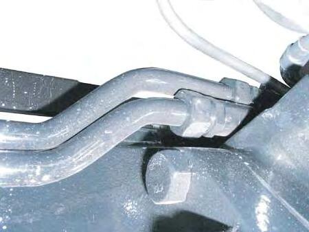
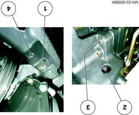
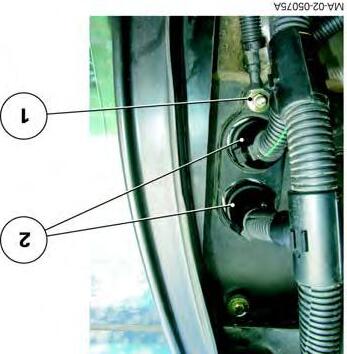
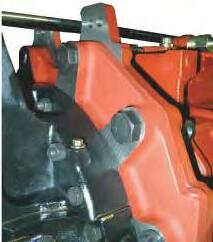
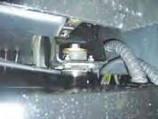
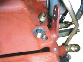
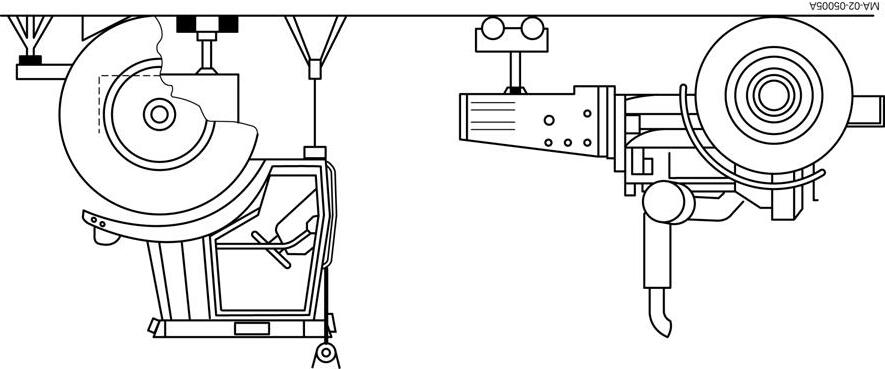
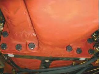
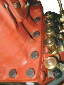
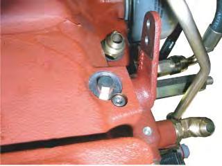
5. Mark then disconnect: -the differential lock hose on the front axle, -the supply hose on the steering ram, -the lubrication hoses (running to and from the cooler) (Fig.1).
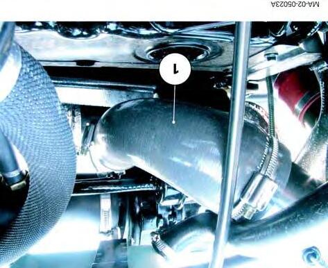
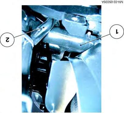
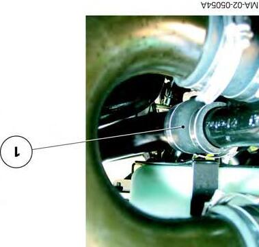
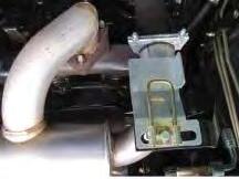
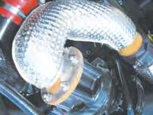
Remove the protective grille close to the radiator. Disconnect the air sleeve (1) (turbo outlet) from the cooling sleeve (Fig.2).
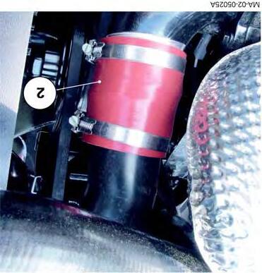
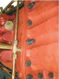
Operations on the left-hand side of the tractor
6. Mark and disconnect the supply hose on the steering ram.
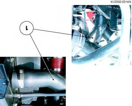
7. Disconnect the air sleeve (2) (inlet on inlet manifold) from the cooling sleeve (Fig.3).
MA-02-05084A
Fig. 1
Fig. 2
Fig. 3
Splitting - Front frame / Perkins engine
Draining the cooling system
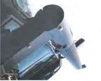
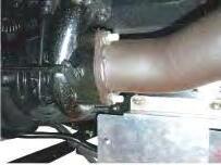
8. Unscrew the fin plug located on the left-hand side and front of the radiator. Drain the liquid into a clean container.
DANGER: If the engine is hot, gradually loosen the expansion tank plug before removing it in order to drive out the pressure from the system.
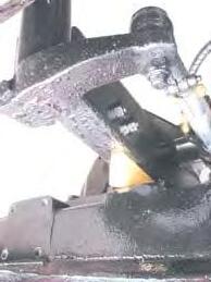
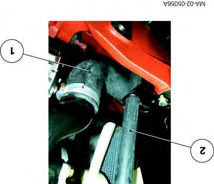
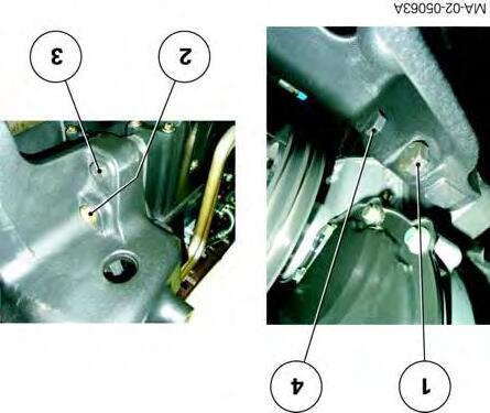
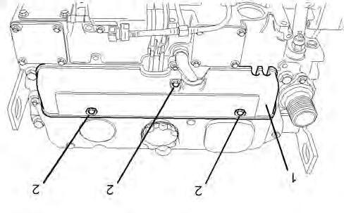
9. Disconnect the lower hose (1) and the hose (2) linking the expansion tank to the base of the radiator (Fig.4).
Operations above the engine
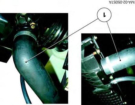
10. Disconnect the upper hose (1) (Fig.5).
Operations at the front of the tractor
11. Remove the weights (if fitted).
12. Detach the air conditioning compressor, the condenser and the filter from their respective supports. Carefully remove them from the engine, without opening up the system (see chapter12).
13. Mark and disconnect the electrical harnesses inside the grille.
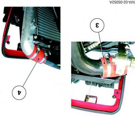
14. Disconnect the air sleeves (3) and (4) on the air cooler located inside the grille (Fig.6).
Fig. 4
Fig. 5
Fig. 6
Splitting - Front frame / Perkins engine
Preparing for disassembly
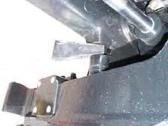
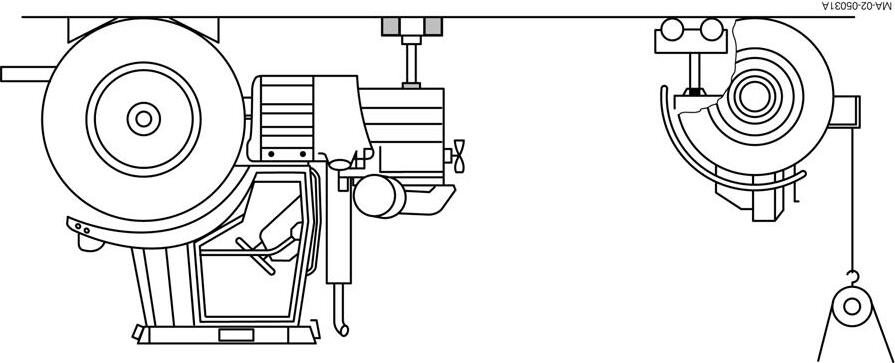
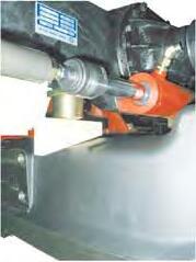
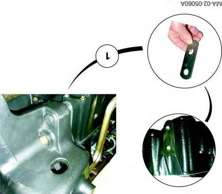
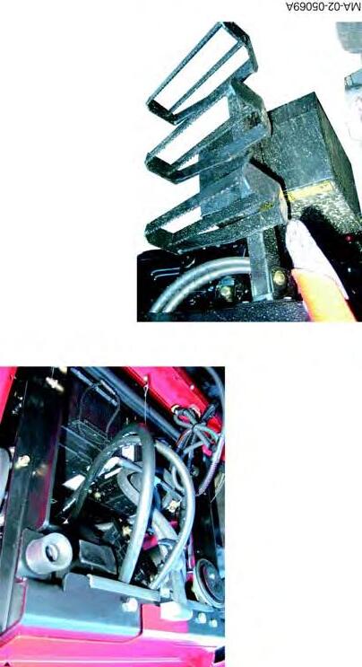
15. Cancel the oscillation, depending on assembly: -of the front axle beam (2WD) or -of the front axle (4WD), by inserting a suitable block on either side of the frame (1) as shown in Fig.7
16. Chock the rear wheels.
17. Install (Fig.9): -a mobile stand under the front axle beam or front axle (depending on assembly); -a suitable sling at the front of the frame; -a fixed axle stand under the engine lower housing.
Disassembly
IMPORTANT: During separation, check that all connections (hoses, pipes and harnesses) are disconnected.
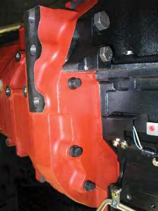
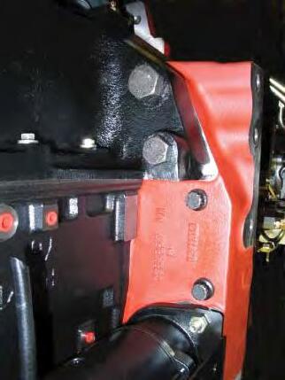
18. Remove the side screws (1) (Fig.8).
19. With the help of an operator, loosen the screws (2)(3) (Fig.8), simultaneously moving the front frame away from the engine.
DANGER: When disconnecting, use the sling to prevent the front frame assembly from tipping over.
MA-02-05085A
Fig. 7
Fig. 8
Fig. 9
Splitting - Front frame / Perkins engine
Reassembly
Screw specifications
Screw
M16 x 55 mm
M16 x 60 mm
M16 x 115 mm
M20 x 190 mm
M24 x 200 mm
20. Clean the mating faces of the engine and front frame.
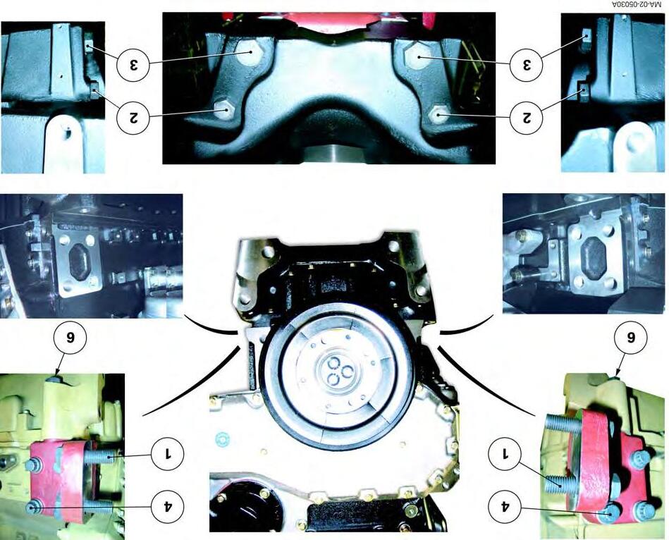
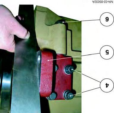
21.Prior to reassembly check with a ruler that the supports (5) are aligned with the front face of the engine lower housing (Fig.11). If not:
-Adjust the support(s) until they are correctly aligned.
-Tighten:
-the screws (4) to a torque of 240-320Nm (Loctite 270 or equivalent);
-the screws (6) to a torque of 240-320Nm.
-Check correct alignment after tightening.
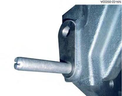
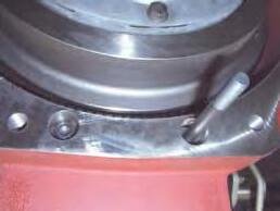
22. Screw a guide stud onto each rear face of the frame (Fig.10).
23. With the help of an operator, connect the front frame to the engine. Take out the guide studs.
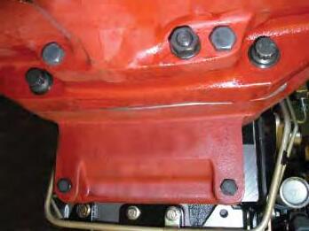
24. Fit and tighten the opposed screws (Fig.13) in the following order:
-screws (2) to a torque of 480-640Nm; -screws (3) to a torque of 800-1040Nm; -screws (1) to a torque of 240-320Nm.
Fig. 10
Fig. 11
CLICK HERE TO DOWNLOAD THE COMPLETE MANUAL
• Thank you very much for reading the preview of the manual.
• You can download the complete manual from: www.heydownloads.com by clicking the link below
• Please note: If there is no response to CLICKING the link, please download this PDF first and then click on it.
CLICK HERE TO DOWNLOAD THE
Splitting - Front frame / Perkins engine
Final steps
The final steps are not especially difficult. However, it will be necessary during reassembly to perform the tightening torques, adjustments and tests described below.
•Tightening torque
As required, wheel screws or nuts (see chapter 6).
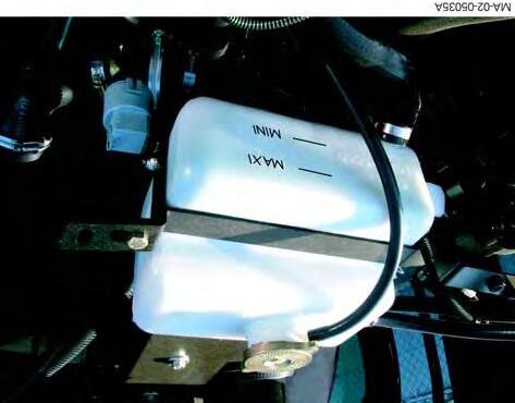
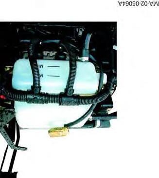
•Topping up of coolant, to the maximum level marked on the expansion tank (Fig.12).
•Test:
-the air conditioning system (if fitted - see chapter12); -all mechanical, hydraulic and electrical functions relating to the operation.
•Check tightness:
-of hydraulic unions, -of water hoses.
Fig. 12
Fig. 13
Splitting - Front frame / Perkins engine
C . Disassembly and reassembly (4-cylinder Perkins engine)
NOTE: Two models of front frame are available for 5400 series tractors with 4-cylinder engines.
Tractors with… Power (hp) front frame without shimming 65 to 95 front frame with shimming 105
Preparation
25. Apply the hand brake.
26. Take off the side panels, prefilter (105hp engine), bonnet and central exhaust pipe (depending on option).
Operations underneath the tractor
27. Take off the guard, transmission shaft and differential lock supply pipe (4WD tractors).
Operations at the front of the tractor
28. Remove the front weights (if fitted).
29. Disconnect the batteries. If required, remove them from the grille compartment.
Tractors with…
Battery location
Perkins engines 65to95hp In the grille compartment
Perkins engines 105hpBehind the right-hand step.
Sloping bonnetBehind the right-hand step.
Location of batteries
30. Detach the air conditioning compressor, the condenser and the filter from their respective supports (if fitted). Place the assembly beside the tractor without disconnecting the pipes and hoses (see chapter12).
Operations inside the grille
Splitting - Front frame / Perkins engine
31. Mark then disconnect: -electrical harnesses, -air sleeves(3) and (4) on the cooler (105hp Perkins engine, Fig.27).
Operations on the right-hand side of the tractor
32. Mark and disconnect the supply hose on the steering ram.
33. Mark and disconnect the lubrication hoses running to and from the cooler (105hp Perkins engine, Fig.15).
34. Remove the protective grille close to the radiator.
35. Disconnect the air sleeve(1) (turbo outlet) from the cooling sleeve (105hp Perkins engine, Fig.16).
Fig. 14
Fig. 15
Fig. 16
Splitting - Front frame / Perkins engine
Operations on the left-hand side of the tractor
36. Mark and disconnect the supply hose on the steering ram.
37. Remove the protective grille close to the radiator.
Draining
the cooling system
38. Unscrew the fin plug located on the left-hand side and front of the radiator, to drain the system.
DANGER: If the engine is hot, gradually loosen the expansion tank plug before removing it in order to drive out the pressure from the system.
39. Disconnect the lower hose (1) and the hose (2) linking the expansion tank to the base of the radiator (Fig.17).
Operations above the engine
40. Disconnect the upper hose (1) (Fig.18).
Fig. 17
Fig. 18
Splitting - Front frame / Perkins engine
Page intentionally left blank
Splitting - Front frame / Perkins engine
Preparing for disassembly
41. Cancel the oscillation, depending on assembly: -of the front axle beam (2WD) or -of the front axle (4WD), by inserting a suitable block on either side of the frame (1) as shown in Fig.19
42. Chock the rear wheels.
43. Install (Fig.22):
-a mobile stand under the front axle beam or front axle (depending on assembly); -a suitable sling at the front of the frame; -a fixed axle stand under the engine lower housing.
Disassembly
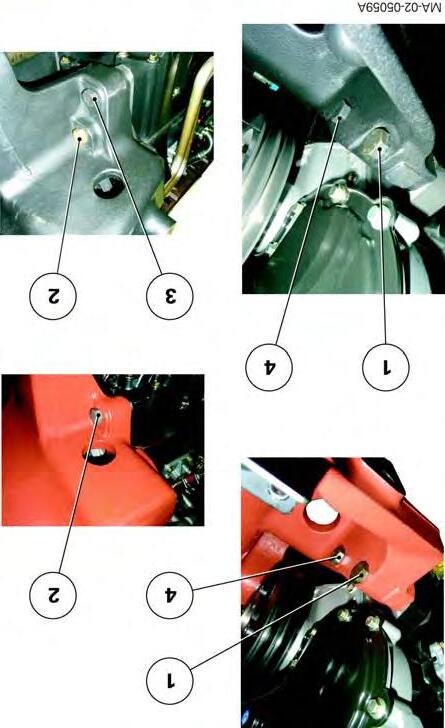
IMPORTANT: During separation, check that all connections (hoses, pipes and harnesses) are disconnected. Mark the position and location of shims(1) inserted between the engine lower housing and front frame (105hp Perkins engine, Fig.20).
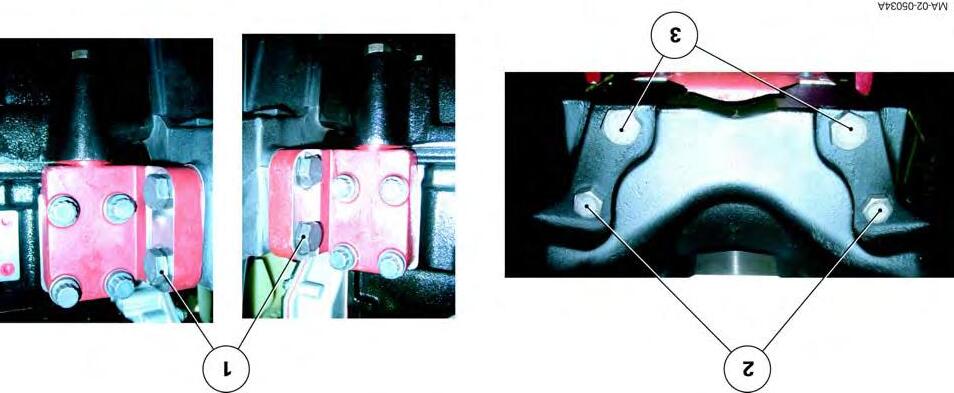
44. Loosen and remove (Fig.21):
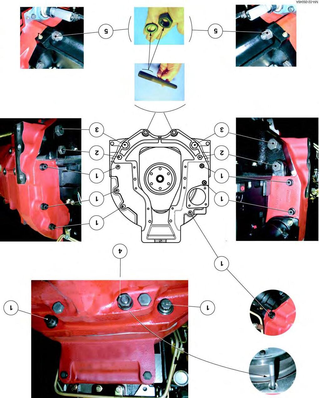
-For Perkins 65 to 95hpengines: screws and bolts(2), (4) and (1);
-for Perkins 105hp engines:screws and bolts(2), (3), (4) and (1).
With the help of an operator, gradually separate the front frame from the engine at the same time.
DANGER: When disconnecting, use the sling to prevent the front frame assembly from tipping over (Fig.22).
MA-02-05086A
Fig. 19
Fig. 20
Splitting - Front frame / Perkins engine
Fig. 21
Fig. 22
Splitting - Front frame / Perkins engine
Reassembly
INSTRUCTIONS: Use guide studs to assist reconnection of the front frame and engine.
Specifications of the screws and nuts
•Front frame and Perkins 65 to 95hp engine
Screw Nuts
M16x75mm
M16x85mm
M16 x 115 mm M16
•Front frame and Perkins 105hp engine
Screw Nuts
M16x85mm
M16x95mm
M16x105mm
M16x120mm
M16
45. Clean the mating faces of the engine and front frame.
46. Screw two guide studs(1) to the front face of the engine (Fig.23).
47. With the help of an operator, reconnect the front frame to the engine as follows:
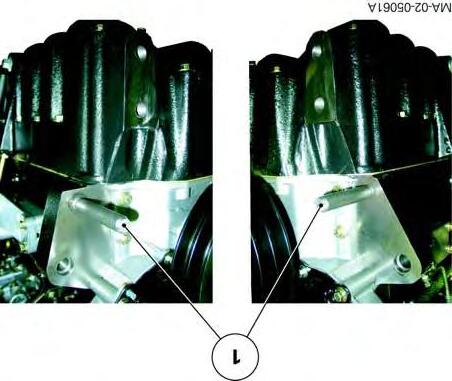
•Front frame and Perkins 65 to 95hp engine (Fig.24)
48. Fit screws(2), (4) and bolts(1), simultaneously taking out the guide studs.
49. Tighten opposing screws and bolts to a torque of 240-320Nm in the following order: (2)(4)(1).
•Front frame and Perkins 105hp engine (Fig.25)
IMPORTANT: If it is necessary to shim the front frame, refer to § D
50. Fit screws(2), (3), (4) and bolts(1), simultaneously taking out the guide studs.
51. Tighten opposing screws and bolts to a torque of 240-320Nm in the following order: (2)(3)(4)(1).
Fig. 23
Fig. 24
Fig. 25
Splitting - Front frame / Perkins engine
Final steps
The final steps are not especially difficult. However, it will be necessary during reassembly to perform the tightening torques, adjustments and tests described below.
•Tightening torque
As required, wheel screws or nuts (see chapter 6).
•Topping up of coolant, to the maximum level marked on the expansion tank (Fig.26).
•Test:
-the air conditioning system (if fitted - see chapter12); -all mechanical, hydraulic and electrical functions relating to the operation.
•Check tightness: -of hydraulic unions, -of water hoses.
Fig. 26
CLICK HERE TO DOWNLOAD THE COMPLETE MANUAL
• Thank you very much for reading the preview of the manual.
• You can download the complete manual from: www.heydownloads.com by clicking the link below
• Please note: If there is no response to CLICKING the link, please download this PDF first and then click on it.
CLICK HERE TO DOWNLOAD THE
Splitting - Front frame / Perkins engine
D . Shimming the front frame (4-cylinder Perkins engine)
When the front frame is fitted to the Perkins 4-cylinder 105 Hp engine, the face of the engine/lower housing is not in contact with the face of the front frame. It is therefore advised to fill this space with shims(1) (Fig.27) whose thickness will be measured and set afterwards.
IMPORTANT: Shimming should only be carried out if the front frame and/or engine have been replaced.
52. With the help of an operator, connect the front frame to the engine.
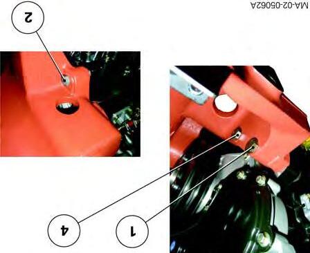
Preparing for shimming (Fig.28)
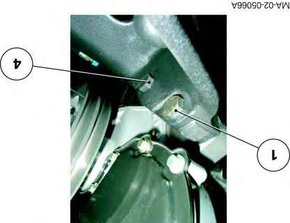
53. Fit only screws (4) and bolts (1), simultaneously taking out the guide studs.
54. Tighten opposing screws and bolts to a torque of 240-320Nm in the following order: (4)(1).
Fig. 27
Fig. 28
Splitting - Front frame / Perkins engine
Shimming
IMPORTANT: To avoid applying undue loads to the mating faces during shimming, avoid adjusting the safety stands placed under the engine and front axle during disassembly.
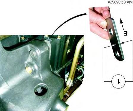
55. Using two stacked shims(1), each at least 2.30mm thick (Fig.29), measure the gap between the faces of the engine/lower housing and front frame.
Determine the thickness of shims to be fitted by increasing, as required, the thickness of each shim until they fit tightly in the gap.
NOTE: Shimming is carried out using shims between 2.30 and 2.60mm thick.
Inserting shims between the front frame and the engine
56. Slightly loosen the screws(4) and bolts(1) (Fig.30).
57. Turn the shims(1)so that end"E" faces downwards. Insert them between the front frame and the engine/lower housing (Fig.29).
58. Fit screws (2) and (3) (Fig.30).
59. Tighten bolts and all screws of the front frame to a torque of 240-320Nm in opposition and in the following order: (2)(3)(4)(1) (Fig.30).
60. Release the safety stands.
Fig. 29
Fig. 30
2B11 - Splitting Perkins engine / GTA2020
CONTENTS
A.General
B.Disassembly and reassembly (Perkins 4-cylinder engine).
C.Replacing the input shaft seal (tractors with dry clutch).
D.Disassembly and reassembly (6-cylinder Perkins engine).
E.Service tool.
Massey Ferguson 5400
Splitting Perkins engine /
A . General
Tractors in the 5400 series fitted with the GBA20 gearbox are fitted with a : -with a 4-cylinderPerkins engine -with a 6-cylinderPerkins engine
Gearbox with Power Shuttle
The tractor should be disconnected between the engine and the gearbox with Power Shuttle when access is necessary to carry out servicing on the main following elements:
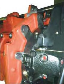
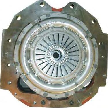
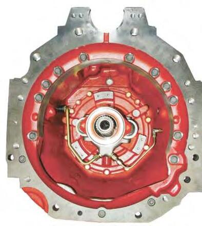
Gearbox with mechanical reverse shuttle (dry clutch)
The tractor should be disconnected between the engine and the gearbox with dry clutch when access is necessary to carry out servicing on the main following elements:
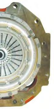
•Engine interface
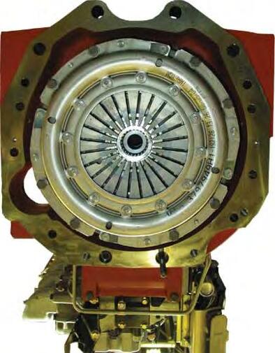
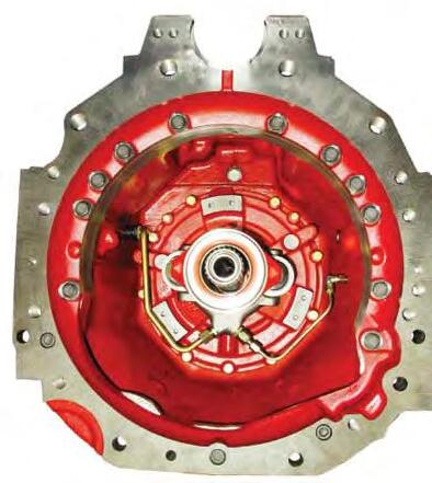
-diaphragm mechanism or friction disc, -engine flywheel -engine adapter plate
-This section describes a general disassembly procedure. Before and during separation, check that all connections between the fixed assembly and mobile assembly have been disconnected.
-The cab remains attached to the centre housing.
Splitting Perkins engine / GTA2020
B . Disassembly and reassembly (Perkins 4-cylinder engine)
Preparation
1. Apply the hand brake.
2. Remove: -the side panels either side of the engine, -the prefilter (Perkins 105 hp engine), -the central exhaust pipe (depending on option), -the bonnet.
Operations under the tractor
3. Take off the guard, 4WD transmission shaft and differential lock supply pipe.
Operations at the front of the tractor
4. Remove the front weights (if fitted).
5. Disconnect the batteries.
Tractors with… Battery location
Perkins engine upto95hp In the grille compartment
Perkins engines 105hpBehind the right-hand step.
Sloping bonnetBehind the right-hand step.
Location of batteries (Fig.1)
Fig. 1
Splitting Perkins engine / GTA2020
Operations on the right-hand side of the tractor
6. Take off the front right-hand mudguard.
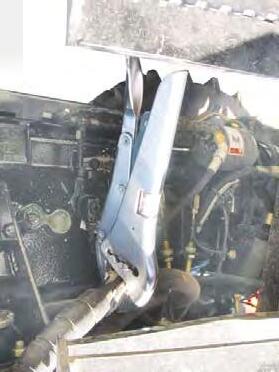
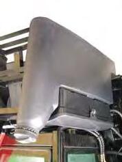
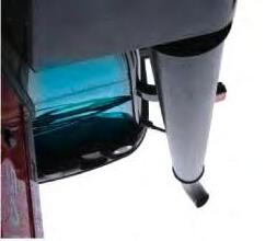
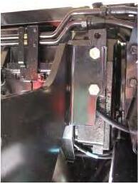
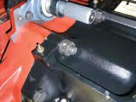
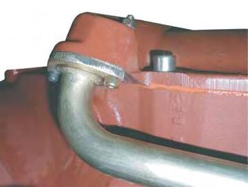
7. If necessary, remove the vertical exhaust assembly (including support) (Fig.2).
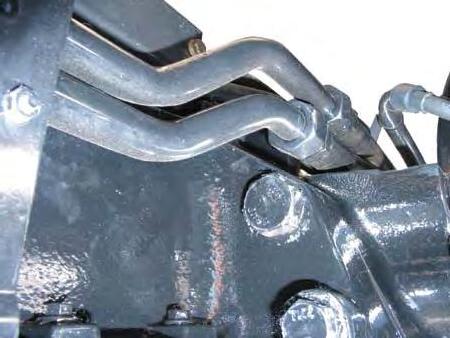
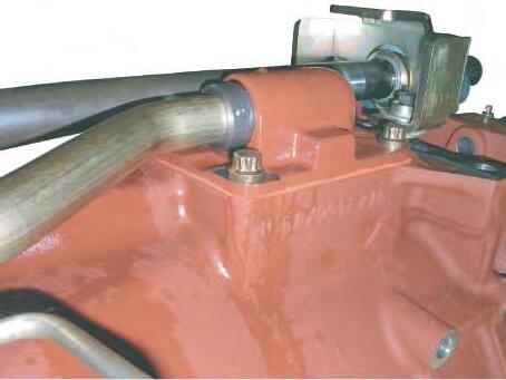
8. Mark then disconnect: -the hose on the steering ram or on the spool valve (Orbitrol), depending on the tractor type -the lubrication hoses running to and from the cooler (105hp Perkins engine, Fig.3).
Operations on the left-hand side of the tractor
9. Take off the front left-hand mudguard.
10. Mark then disconnect: -the hose on the steering ram or on the spool valve (Orbitrol), depending on the tractor type; -the fuel feed and return hoses on the engine, immediately blocking the ports.
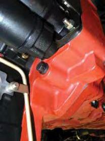
11. Disconnect the cables connected to the positive terminal of the starter (Fig.4).
MA-02-05093A
Fig. 2
Fig. 3
Fig. 4
Splitting Perkins engine / GTA2020
Operations under the cab
CAUTION: If the engine is still hot, allow it to cool.
NOTE: To work on the heating hoses, it is not necessary to drain the engine block cooling system.
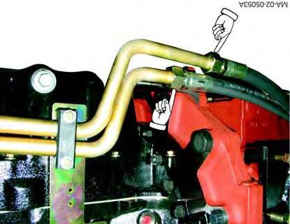
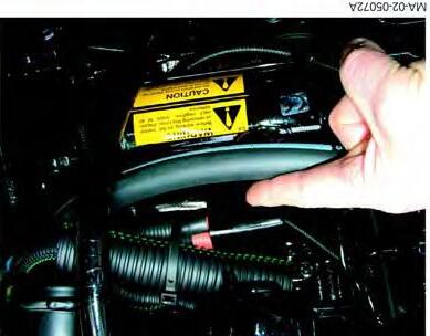
12. Mark and pinch out each heating hose using a clamp fitted with protective jaws (Fig.5). Disconnect them, immediately blocking the ports.
Operations on the engine
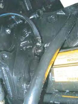
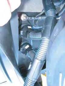
13. Disconnect the negative cables on the block at the rear left-hand side of the engine (Fig.6).
14. Detach the air conditioning compressor, the condenser and the filter from their respective supports (if fitted). Carefully move them from the engine, without disconnecting the pipes and hoses (see chapter12).
Operations at the front of the cab
15. Disconnect the connectors(2) and the ground terminals(1) on the left-hand side of the cab bulkhead (Fig.7).
MA-02-05094A
Fig. 5
MA-02-05095A
Fig. 6
Fig. 7
CLICK HERE TO DOWNLOAD THE COMPLETE MANUAL
• Thank you very much for reading the preview of the manual.
• You can download the complete manual from: www.heydownloads.com by clicking the link below
• Please note: If there is no response to CLICKING the link, please download this PDF first and then click on it.
CLICK HERE TO DOWNLOAD THE
Splitting Perkins engine / GTA2020
Preparing for disassembly
16. Cancel the oscillation: -of the front axle beam (2WD) or -of the front axle (4WD), by inserting a suitable wooden block on either side of the frame (1) as shown in Fig.8
17. Chock the rear wheels.
18. Install (Fig.9): -a fixed axle stand at the front of the gearbox -a mobile axle stand at the rear of the engine -a mobile axle stand under the front frame.
19. If necessary, separate the cab from the front right and left-hand supports (see chapter12).
20. Gently lift the front of the cab using two straps fitted to the side handles.
DANGER: Make the area around the cab safe by temporarily placing a wooden chock between each front support and the right and left-hand cab attachments.
MA-02-05096A
Fig. 8
MA-02-05090A
Fig. 9
Splitting Perkins engine / GTA2020
Disassembly
IMPORTANT: During separation, check that all connections (hoses, pipes and harnesses) are disconnected.
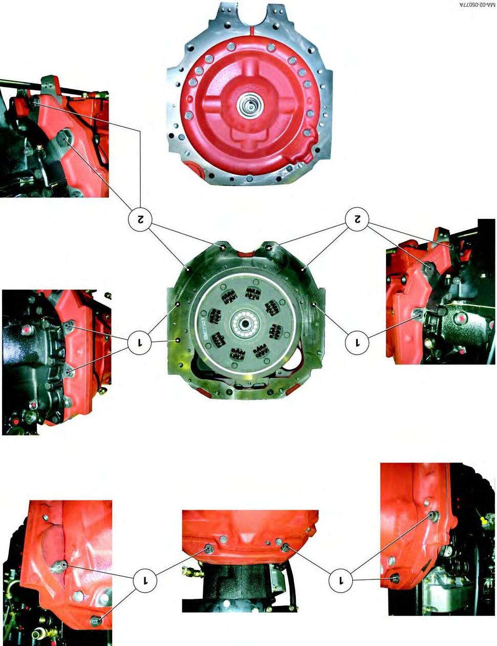
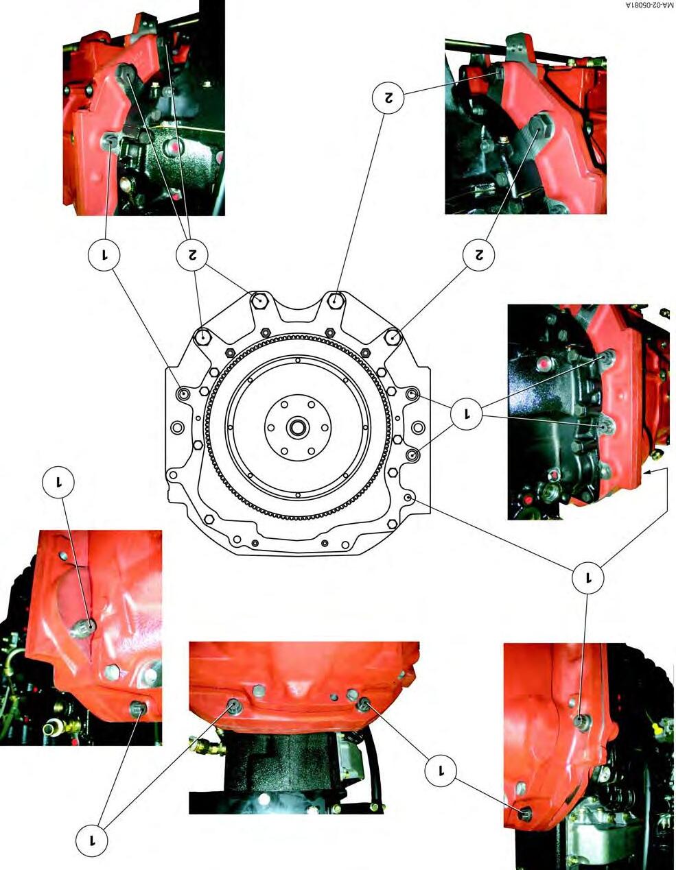
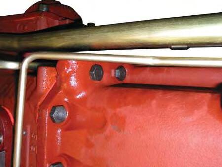
21. Remove the screws attaching the engine to the gearbox (Fig.14 depending on assembly). Mark their length and position.
NOTE:
The tractor may be fitted with one or two fuel tanks (depending on option):
- Assembly1: a single fuel tank on the left-hand side of the tractor
- Assembly2: a fuel tank on each side of the tractor. In this configuration, remove the right-hand fuel tank from the gearbox if it blocks access to the screws and nuts.
Screw specifications
Screw
M16 x 50 mm
M16 x 60 mm
M16 x 80 mm
M22 x 80 mm
22. Assisted by an operator, separate the assemblies (Fig.9).
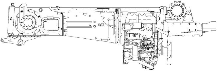
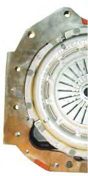
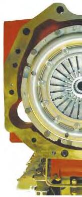
Engine/GBA20 transmission with Power Shuttle connection
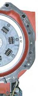
Fig. 10
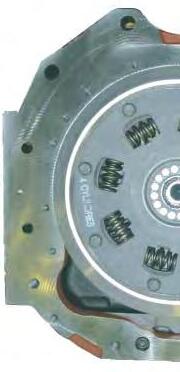
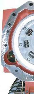
Engine/GBA20 transmission with mechanical reverse shuttle connection
Massey
Fig. 11
Splitting Perkins engine / GTA2020
Reassembly
23. Clean the mating faces of the engine and the gearbox spacer.
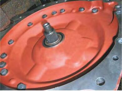
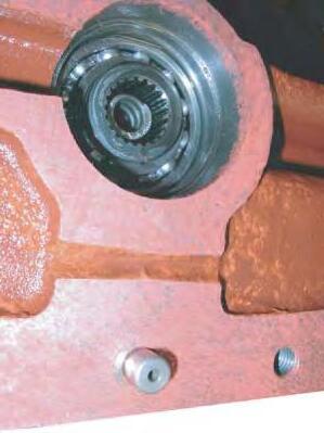
24. Check that the dowels (1) are present on the engine (Fig.12).
25. Depending on the tractor type, carry out the following operations.
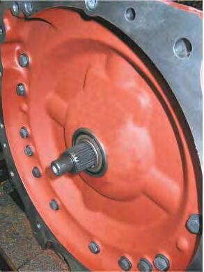
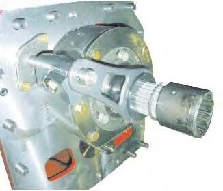
•Tractors with Power Shuttle (Fig.13)
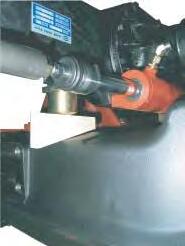
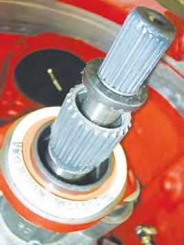
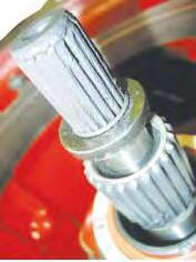
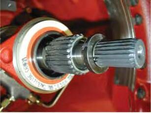
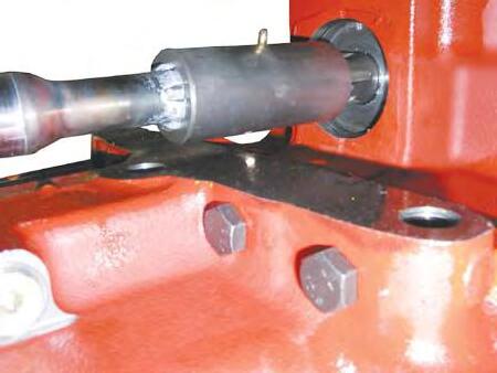
Lightly smear the splines of the input shaft (1) with AS767 graphite grease or equivalent.
•Tractors with dry clutch (Fig.13)
Replace the seal (2) on the input shaft (1) (see § C).
Lightly smear the splines of the input shaft (1) and PTO shaft (3) with AS767 graphite grease or equivalent.
26. Screw two diametrically opposed guide studs onto the engine adaptor plate or onto the gearbox spacer.
MA-02-05098A
Fig. 12
MA-02-05099A
Fig. 13
Splitting Perkins engine / GTA2020
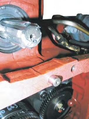
27. Connect the engine to the gearbox spacer.
IMPORTANT: If necessary, remove the starter and turn the engine flywheel ring gear using a suitable tool. This will ease the engagement of the splines of the vibration damper or friction disc (depending on assembly) with those of the input shaft. If there is resistance, do not force it; find the cause of the problem.
28. Once the elements are joined, remove the guide studs.
29. Lightly smear the thread of each screw (1) and (2) with Loctite270 or equivalent.
Position them according to the marks made during disassembly.
Tighten (Fig.14):
-screws(1) to a torque of240-320Nm;
-screws(2) to a torque of630-840Nm.
Final steps
The final steps are not especially difficult. However, it will be necessary during reassembly to perform the tightening torques, adjustments and tests described below.
•Tightening torque
As required, front cab screws (see chapter12).
•Topping up of coolant, to the maximum level marked on the expansion tank (Fig.14).
•Test:
-the air conditioning system (if fitted - see chapter12); -all mechanical, hydraulic and electrical functions relating to the operation.
•Checking tightness of hydraulic unions.
Fig. 14
15
Fig.
Splitting Perkins engine / GTA2020
C . Replacing the input shaft seal (tractors with dry clutch)
Preliminary steps
30. Disconnect the tractor between the engine and the gearbox (see chapter2).
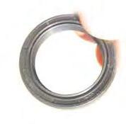
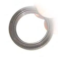
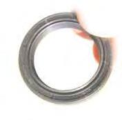
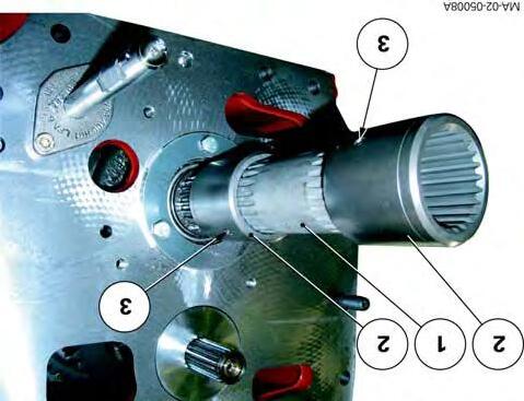
Preparing for seal (2) replacement (Fig.16)
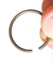
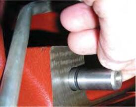
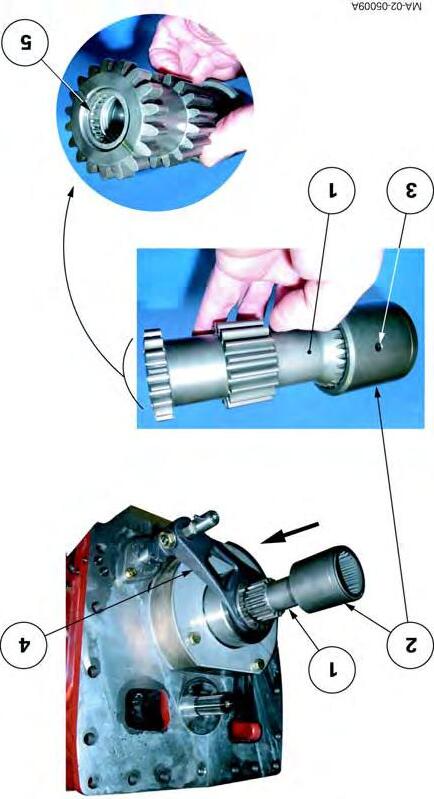
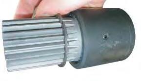
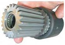
31. Take the PTO shaft (3) out of the input shaft (1). Remove the snap ring (4) and the splined washer (5).
32. Take the worn seal (2) out of the input shaft (1) without using a sharp or pointed tool.
33. Clean the components.
34. Check there are no scratches: -in the seating of the seal (2) on the input shaft (1), -on the PTO shaft (3) at the seating of the lip of the seal (2).
Fig. 16
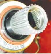
Replacing the seal (2) (Fig.16)
Splitting Perkins engine / GTA2020
35. Turn the PTO shaft (3) as required. Slide it into the input shaft (1).
36. Cover the PTO shaft splines with a flexible protection.
37. Smear the internal cavity of the seal (2) with miscible grease.
38. Position the seal (2) on the PTO shaft (3) so that its lip, when operating, is in contact with the transmission oil.
Remove the flexible protection.
Fit the seal (2) into the input shaft (1) using tool 3376803M1 (see § E).
IMPORTANT: Ensure that there are no seal fragments after fitting.
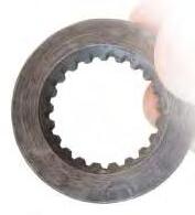
39. Slide the splined washer (5) onto the PTO shaft (3), turning its chamfer C towards the operator.
40. Fit a new snap ring (4) on the PTO shaft (3), opening it as little as possible. Check that it is positioned correctly at the bottom of the groove.
Final step
41. Reconnect the tractor between the engine and the gearbox (see chapter2).
CLICK HERE TO DOWNLOAD THE COMPLETE MANUAL
• Thank you very much for reading the preview of the manual.
• You can download the complete manual from: www.heydownloads.com by clicking the link below
• Please note: If there is no response to CLICKING the link, please download this PDF first and then click on it.
CLICK HERE TO DOWNLOAD THE
Splitting Perkins engine / GTA2020
D . Disassembly and reassembly (6-cylinder Perkins engine)
Preparation
1. Apply the hand brake.
2. Remove: -the side panels either side of the engine, -the prefilter, -the bonnet.
Operations under the tractor
3. Take off the guard, 4WD transmission shaft and differential lock supply pipe.
Operations at the front of the tractor
4. Remove the front weights (if fitted).
Operations on the right-hand side of the tractor
5. Disconnect the batteries.
6. Remove the vertical exhaust assembly (including support Fig.1).
7. Mark then disconnect: -the cables (positive and negative) on the starter -the supply hose on the steering ram, -the lubrication hoses (running to and from the cooler) (Fig.2).
Operations on the left-hand side of the tractor
8. Mark and disconnect the supply hose on the steering ram.
9. Mark and disconnect the fuel feed and return hoses on the engine, immediately blocking the ports.
MA-02-05087A
Fig. 1
MA-02-05088A
Fig. 2
Splitting Perkins engine / GTA2020
Operations under the cab
10. Mark, pinch out and disconnect each heating hose, immediately blocking the ports.
Operations on the engine
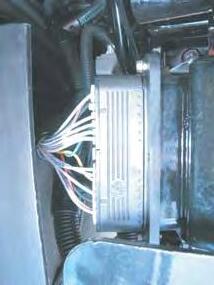
11. If necessary, disconnect the connector (3) of the main wiring harness (Fig.3).
12. Detach the air conditioning compressor, the condenser and the filter from their respective supports (if fitted). Carefully remove them from the engine, without opening up the system (see chapter12).
Operations at the front of the cab
13. Disconnect the connectors(2) and the ground terminals(1) on the left-hand side of the cab bulkhead (Fig.3).
Preparing for disassembly
14. Cancel the oscillation, depending on assembly: -of the front axle beam (2WD) or -of the front axle (4WD), by inserting a suitable block on either side of the frame (1) as shown in Fig.4
15. Chock the rear wheels.
MA-02-05040B
Fig. 3
MA-02-05089A
Fig. 4
Splitting Perkins engine / GTA2020
16. Install (Fig.5): -a fixed axle stand at the front of the gearbox -a mobile axle stand at the rear of the engine -a mobile axle stand under the front frame.
17. If necessary, separate the cab from the front right and left-hand supports (see chapter12).
18. Gently lift the front of the cab using two straps fitted to the side handles.
DANGER: Make the area around the cab safe by temporarily placing a wooden chock between each front support and the right and left-hand cab attachments.
Disassembly
IMPORTANT: During separation, check that all connections (hoses, pipes and harnesses) are disconnected.
19. Remove the screws and nuts attaching the engine to the gearbox (Fig.6 or Fig.7 depending on assembly). Mark their length and position.
NOTE:
The tractor may be fitted with one or two fuel tanks (depending on option):
- Assembly1: a single fuel tank on the left-hand side of the tractor
- Assembly2: a fuel tank on each side of the tractor. In this configuration, remove the right-hand fuel tank from the gearbox if it blocks access to the screws and nuts.
Specifications of the screws, studs and nuts
Screw Studs Nuts
M16 x 60 mm
M16 x 115 mm
M16 x 185 mm
M22 x 160 mm M12 x 185 mm M22 x 160 mm M12 M22
20. Assisted by an operator, separate the assemblies (Fig.5).
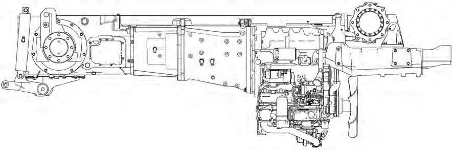
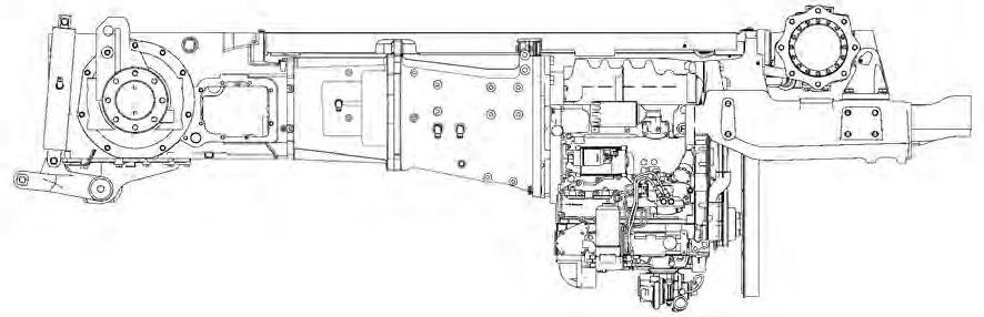
Splitting
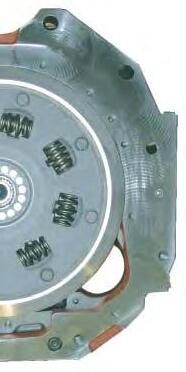
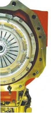
Engine/GBA20 transmission with Power Shuttle connection
Fig. 6
Engine/GBA20 transmission with mechanical reverse shuttle (dry clutch) connection
Fig. 7
Splitting Perkins engine / GTA2020
Reassembly
21. Clean the mating faces of the engine and the gearbox spacer.
22. Check:
-the presence of dowels (1) on the engine (Fig.8)
-the tightness of the upper stud (M12) on the engine adapter plate (Loctite270),
-the tightness of the lower studs (M22) on the gearbox spacer (Loctite270).
23. Depending on the tractor type, carry out the following operations.
•Tractors with Power Shuttle (Fig.9)
Lightly smear the splines of the input shaft (1) with AS767 graphite grease or equivalent.
•Tractors with dry clutch (Fig.9)
Replace the seal (2) on the input shaft (1) (see § C).
Lightly smear the splines of the input shaft (1) and PTO shaft (3) with AS767 graphite grease or equivalent.
24. If necessary, screw two extra diametrically opposed guide studs into the gearbox.
MA-02-05091A
Fig. 8
Massey Ferguson 5400
Fig. 10
25. Connect the engine to the gearbox spacer.
Splitting Perkins engine / GTA2020
IMPORTANT: If necessary, remove the starter and turn the engine flywheel ring gear using a suitable tool. This will ease the engagement of the splines of the vibration damper or friction disc (depending on assembly) with those of the input shaft. If there is resistance, do not force it; find the cause of the problem.
26. Once the elements are joined, remove the guide studs (if fitted).
27. Lightly smear the thread of the each screw and nut with Loctite270 or equivalent.
Position them according to the marks made during disassembly.
Tighten (Fig.10):
-screws(1) to a torque of240-320Nm; -screws(2) to a torque of240-320Nm;
-screws(3) to a torque of630-840Nm. -nuts (4) to a torque of 100-130Nm; -nuts (5) to a torque of 630-840Nm.
Final steps
The final steps are not especially difficult. However, it will be necessary during reassembly to perform the tightening torques, adjustments and tests described below.
•Tightening torque
As required:
-Front cab screws (see chapter12)
-Screws (2) of connector (3) on main wiring harness from 2.82 to 3.15Nm (Fig.3 and Fig.11).
•Topping up of coolant, to the maximum level marked on the expansion tank (Fig.12).
•Test:
-the air conditioning system (if fitted - see chapter12); -all mechanical, hydraulic and electrical functions relating to the operation.
•Checking tightness of hydraulic unions.
Fig. 11
Fig. 12
Splitting Perkins engine / GTA2020
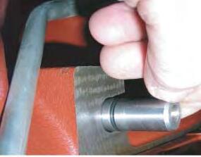
E . Service tool
Tool available in the AGCO network
• 3376803M1: Fitting drift for input shaft seal (tractors with dry clutch) (Fig.13)
MA-02-05101A
Fig. 13
CLICK HERE TO DOWNLOAD THE COMPLETE MANUAL
• Thank you very much for reading the preview of the manual.
• You can download the complete manual from: www.heydownloads.com by clicking the link below
• Please note: If there is no response to CLICKING the link, please download this PDF first and then click on it.
CLICK HERE TO DOWNLOAD THE
Splitting GBA20/GPA20 (cab fixed to centre housing)
2C11 - Splitting GBA20/GPA20 (cab fixed to centre housing)
CONTENTS
A.General .
Massey Ferguson 5400
Splitting GBA20/GPA20 (cab fixed to centre housing)
A . General
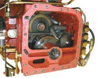
Disconnecting the tractor with the cab fixed to the centre housing allows access: -to the gearbox output shaft, -to the creeper or super creeper unit and selection mechanism (depending on option), -to the PTO clutch, -to the hand brake mechanism.
IMPORTANT: This section describes a general disassembly procedure. Before and during separation, check that all connections between the fixed assembly and mobile assembly have been disconnected.
Splitting GBA20/GPA20 (cab fixed to centre housing)
B . Disassembly and reassembly with the cab fixed to the centre housing
Preparation
1. Apply the hand brake.
2. Remove: -the side panels either side of the engine, -the prefilter, -the central exhaust pipe (depending on option), -the bonnet (if necessary).
3. Remove the steps.
4. Disconnect the batteries.
Tractors with… Battery location
Perkins engines 65to95hp In the grille compartment
Perkins engines 105hpBehind the right-hand step.
Sloping bonnetBehind the right-hand step.
Location of batteries (Fig.1)
Fig. 1
Splitting GBA20/GPA20 (cab fixed to centre housing)
Operations underneath the tractor
5. Take off the guard, 4WD transmission shaft and differential lock supply pipe.
6. Drain the oil from the gearbox and centre housing.
7. Remove the lubrication pipe (1) of the Power Shuttle (if fitted) located between the centre housing and gearbox (Fig.2).
Operations on the right-hand side of the tractor
8. Remove the batteries and their support located behind the right-hand step.
9. Mark then disconnect:
-the hose on the steering ram or spool valve (Orbitrol),
-the main pipe (17bar) to the selector cover plate, -the front differential lock hose on the right-hand hydraulic cover plate
-the return hoses on the selector cover plate
-the gear cable and rod on the selector cover plate,
-the creeper or super creeper gear cable (depending on option).
MA-02-05103A
Fig. 2
Splitting GBA20/GPA20 (cab fixed to centre housing)
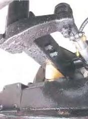
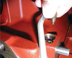
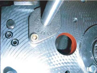
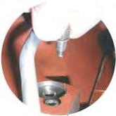
10. On tractors fitted with a creeper or super creeper unit (Fig.3), carry out the following operations. -Remove the rod (3) (if necessary). -Remove the screw (2).
-Pull the pin (1) outwards in order to free the "D" finger of the final drive fork.
11. Mark and disconnect the electrical connectors on: -the right and left-hand hydraulic cover plates, -the selector cover plate; -the Speedshift solenoid valve, -Power Shuttle proportional solenoid valves (if fitted).
Operations on the left-hand side of the tractor
12. Mark then disconnect:
-the hose on the steering ram or spool valve (Orbitrol), -the harness of the fuel gauge on the fuel tank -the fuel feed and return hoses on the engine, immediately blocking the ports, -the vent hose on the fuel tank.
13. Drain the tank (if necessary). Remove it.
14. Disconnect the transmission lubrication supply line (pipes and hoses) located to the front and left of the gearbox.
Fig. 3
Splitting GBA20/GPA20 (cab fixed to centre housing)
Operations under the cab
15. Mark and pinch out each heating hose using a clamp fitted with protective jaws (Fig.4). Disconnect them, immediately blocking the ports.
Operations on the engine
16. Disconnect: -the connector of the main engine harness, -the throttle control cable on the injection pump (4-cylinder Perkins engine only).
17. Detach the air conditioning compressor, the condenser and the filter from their respective supports. Carefully remove them from the engine, without opening up the system (see chapter12).
Preparing for disassembly
18. Cancel the oscillation, depending on assembly: -of the front axle beam (2WD) or -of the front axle (4WD), by inserting a suitable wooden block on either side of the frame (1) as shown in Fig.5
19. Chock the rear wheels.
MA-02-05094A
Fig. 4
MA-02-05089A
Fig. 5
Splitting GBA20/GPA20 (cab fixed to centre housing)
20. Install (Fig.6):
-a fixed axle stand at the front of the centre housing, -a fixed axle stand at the rear of the hitch hook, -a mobile axle stand at the rear of the gearbox.
21. If necessary, separate the cab from the front right and left-hand supports (see chapter12).
22. Gently lift the front of the cab using two straps fitted to the side handles.
DANGER: Make the area around the cab safe by temporarily placing a wooden chock between each front support and the right and left-hand cab attachments.
Disassembly
IMPORTANT: During separation, check that all connections (hoses, pipes and harnesses) are disconnected.
23. Remove the screws (1) and nuts (2) fixing the gearbox to the centre housing (Fig.7). Mark their length and position.
Specifications of the screws and nuts
Screws (1)
M14 x 45 mm
M14 x 60 mm
Nuts (2)
M14 x 70 mm M14
24. Remove the wooden chocks inserted during step 22
25. Assisted by an operator, separate the assemblies (Fig.6).
26. Hold the cab still using suitable axle stands positioned under the right and left-hand supports (Fig.6).
6
Fig.
Splitting GBA20/GPA20
Fig. 7
Splitting GBA20/GPA20 (cab fixed to centre housing)
Reassembly
27. Clean the mating faces of the gearbox and the centre housing.
On the centre housing
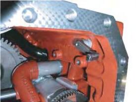
28. Check the presence of dowels (4) (Fig.8). NOTE: The dowels are force fitted.
29. Position the spring (1) in the PTO clutch (Fig.9).
30. Smear the mating face of the centre housing with Loctite5206 or equivalent, avoiding the Hare and Tortoise ports.
31. Replace the "O" rings (2) (Fig.9).
32. If necessary, screw two diametrically opposed guide studs onto the centre housing.
MA-02-05109A
Fig. 8
5206
MA-02-05106A
Fig. 9
On the gearbox
Splitting GBA20/GPA20 (cab fixed to centre housing)
33. Check that the PTO shaft is present and positioned correctly.
34. Depending on the option, carry out the following actions.
•Gearbox without creeper or super creeper unit (Fig.10)
Check the correct assembly of the connecting shaft (1) fitted with the sleeves (2) and double pins (3).
• Gearbox with creeper unit (Fig.11)
Check:
-the correct assembly of the connecting shaft (1) fitted with the sleeve (2) and double pin (3), -that the control mechanism (fork and coupler) is operating correctly in each position. Push the fork (4) towards the front of the gearbox in direct drive position.
NOTE: The output shaft of the gearbox with creeper unit supports the connecting shaft (1) via the needle roller bearing (5).
Fig. 10
Fig. 11
Splitting GBA20/GPA20 (cab fixed to centre housing)
• Gearbox with super creeper unit (Fig.12)
Check: -the presence of the connecting shaft (1) fitted with the sleeve (2) and double pin (3), -that the control mechanism (fork and coupler) is operating correctly in each position. Push the fork (4) towards the front of the gearbox in super creeper position.
NOTE: The output shaft of the gearbox with super creeper unit supports the connecting shaft (1) via the needle roller bearing (5).
MA-02-05107A
Fig. 12
Splitting GBA20/GPA20 (cab fixed to centre housing)
On the centre housing (Fig.13)
35. Pull the pin (1) outwards. Turn finger D towards the front of the centre housing (version with creeper or super creeper unit).
36. Attach the gearbox to the centre housing. IMPORTANT: If there is resistance when moving the elements (gearbox, centre housing) together, do not force them; find the cause of the problem.
37. Once the elements are joined, remove the guide studs (if fitted).
38. Fit the screws (1) and nuts (2) (Fig.7) according to the marks made during disassembly. Tighten the screws and nuts to a torque of 155-195Nm.
39. Engage finger D in the fork of the creeper or super creeper unit (if fitted).
40. Fit a new seal on the screw (2) (Fig.13). Lightly smear the thread of the screw (2) with Loctite242 or equivalent. Tighten the screw moderately.
41. Refit the rod (3) (if fitted).
Fig. 13
Splitting GBA20/GPA20 (cab fixed to centre housing)
Final steps
The final steps are not especially difficult. However, it will be necessary during reassembly to perform the tightening torques, adjustments and tests described below.
•Tightening torque:
-Front cab screws (see chapter12)
-Rear wheel screws or nuts (see chapter 6).
•Top up:
-Transmission oil in the housings (check using the gauge located at the rear of the centre housing)
-Coolant, to the maximum level marked on the expansion tank.
•Adjustment:
-of the creeper or super creeper gear cable (if fitted),
-of the control rod and cable of the four basic gears, -of the throttle control cable on the injection pump (4-cylinder engine only).
•Test:
-the air conditioning system (if fitted - see chapter12); -the mechanical reverse shuttle or Power Shuttle (depending on option), -the four basic gears, -the Hare and Tortoise ranges -the Speedshift, -the creeper or super creeper unit (depending on option).
•Check tightness:
-the mating faces;
-Hydraulic unions
2C13 - Splitting GBA20/GPA20 (cab fixed to gearbox)
CONTENTS
A.General
B.Disassembly and reassembly with the cab fixed to the gearbox
Massey Ferguson
Splitting GBA20/GPA20 (cab fixed to
A . General
Disconnecting the tractor with the cab fixed to the gearbox is quite similar to disconnecting with the cab fixed to the centre housing. However, all disassembly operations close to the centre housing required to make the rear axle mobile must also be included.
Disconnecting the tractor in this way allows replacement: -of the rear axle crownwheel and pinion -of the centre housing.
IMPORTANT: This section describes a general disassembly procedure. Before and during separation, check that all connections between the fixed assembly and mobile assembly have been disconnected.
Splitting GBA20/GPA20 (cab fixed to gearbox)
B . Disassembly and reassembly with the cab fixed to the gearbox
Preparation
1. Apply the hand brake.
2. Remove: -the side panels either side of the engine, -the prefilter, -the central exhaust pipe (depending on option), -the bonnet (if necessary).
3. Remove the steps.
4. Disconnect the batteries.
Tractors with… Battery location
Perkins engines 65to95hp In the grille compartment
Perkins engines 105hpBehind the right-hand step.
Sloping bonnetBehind the right-hand step.
Location of batteries (Fig.1)
Fig. 1
Splitting GBA20/GPA20 (cab fixed to gearbox)
Operations underneath the tractor
5. Take off the guard, 4WD transmission shaft and differential lock supply pipe.
6. Drain the oil from the gearbox and centre housing.
7. Remove the lubrication pipe (1) of the Power Shuttle (if fitted) located between the centre housing and gearbox (Fig.2).
Operations on the right-hand side of the tractor
8. Remove the batteries and their support located behind the right-hand step.
9. Mark then disconnect:
-the main pipe (17bar) to the selector cover plate, -the front differential lock hose on the right-hand hydraulic cover plate
-the return hoses on the selector cover plate
-the gear cable and rod on the selector cover plate (if necessary)
-the creeper or super creeper gear cable (depending on option).
MA-02-05103A
Fig. 2
Splitting GBA20/GPA20 (cab fixed to gearbox)
10. On tractors fitted with a creeper or super creeper unit (Fig.3), carry out the following operations. -Remove the rod (3) (if necessary). -Remove the screw (2). -Pull the pin (1) outwards in order to free the "D" finger of the final drive fork.
11. Mark and disconnect the electrical connectors on: -the right and left-hand hydraulic cover plates, -the selector cover plate; -the Speedshift solenoid valve, -Power Shuttle proportional solenoid valves (if fitted).
Operations on the left-hand side of the tractor
12. Mark then disconnect: -the harness of the fuel gauge on the fuel tank -the fuel feed and return hoses on the engine, immediately blocking the ports, -the vent hose on the fuel tank.
13. Drain the tank (if necessary). Remove it.
14. Disconnect the transmission lubrication supply line (pipes and hoses) located to the front and left of the gearbox.
Fig. 3
Splitting GBA20/GPA20 (cab fixed to gearbox)
Operations under the cab
15. Mark then disconnect: -the right and left-hand brake hoses, -the control hose of the trailer brake valve (if fitted), immediately blocking the ports, -the hand brake cable, -the speed sensor connectors (power take-off and forward speed).
Operations at the rear of the tractor
16. Mark and disconnect the control cables: -of the auxiliary spool valves, -of the PTO (all versions).
17. Mark and disconnect the connectors: -of the linkage valve -of the PTO -of the draft sensor (top link).
Preparing for disassembly
18. Cancel the oscillation, depending on assembly: -of the front axle beam (2WD) or -of the front axle (4WD), by inserting a suitable wooden block on either side of the frame (1) as shown in Fig.4
19. Chock the front wheels.
MA-02-05089A
Fig. 4
Splitting GBA20/GPA20 (cab fixed to gearbox)
20. Install (Fig.5): -a fixed axle stand at the rear of the gearbox, -a mobile axle stand at the front of the rear axle, -a mobile axle stand at the rear of the hitch hook.
21. Separate the cab from the right and left-hand rear supports (see chapter12).
22. Gently lift the cab rear using two straps fitted to the hooks on the rear lower pillars.
DANGER: Make the area around the cab safe by temporarily inserting a wooden chock between each rear support and the right and left-hand cab attachments.
Disassembly
IMPORTANT: During separation, check that all connections (hoses, pipes and harnesses) are disconnected.
23. Remove the screws (1) and nuts (2) fixing the gearbox to the centre housing (Fig.6). Mark their length and position.
Specifications of the screws and nuts
Screws (1) Nuts (2)
M14 x 45 mm
M14 x 60 mm
M14 x 70 mm M14
24. Remove the wooden chocks inserted during step 22
25. Assisted by an operator, separate the assemblies (Fig.5).
26. Hold the cab still using suitable axle stands positioned under the right and left-hand supports (Fig.5).
5
Fig.
Fig. 6
Splitting GBA20/GPA20 (cab fixed to gearbox)
Reassembly
27. Clean the mating faces of the gearbox and the centre housing.
On the centre housing
28. Check the presence of dowels (4) (Fig.7). NOTE: The dowels are force fitted.
29. Position the spring (1) in the PTO clutch (Fig.8).
30. Smear the mating face of the centre housing with Loctite5206 or equivalent, avoiding the Hare and Tortoise ports.
31. Replace the "O" rings (2) (Fig.8).
32. If necessary, screw two diametrically opposed guide studs onto the centre housing.
MA-02-05109A
Fig. 7
5206
MA-02-05106A
Fig. 8
On the gearbox
Splitting GBA20/GPA20 (cab fixed to gearbox)
33. Check that the PTO shaft is present and positioned correctly.
34. Depending on the option, carry out the following actions.
•Gearbox without creeper or super creeper unit (Fig.9)
Check the correct assembly of the connecting shaft (1) fitted with the sleeves (2) and double pins (3).
• Gearbox with creeper unit (Fig.10)
Check:
-the correct assembly of the connecting shaft (1) fitted with the sleeve (2) and double pin (3), -that the control mechanism (fork and coupler) is operating correctly in each position. Push the fork (4) towards the front of the gearbox in direct drive position.
NOTE: The output shaft of the gearbox with creeper unit supports the connecting shaft (1) via the needle roller bearing (5).
Fig. 9
Fig. 10
Splitting GBA20/GPA20 (cab fixed to gearbox)
• Gearbox with super creeper unit (Fig.11)
Check: -the presence of the connecting shaft (1) fitted with the sleeve (2) and double pin (3), -that the control mechanism (fork and coupler) is operating correctly in each position. Push the fork (4) towards the front of the gearbox in super creeper position.
NOTE: The output shaft of the gearbox with super creeper unit supports the connecting shaft (1) via the needle roller bearing (5).
MA-02-05107A
Fig. 11
Splitting GBA20/GPA20 (cab fixed to gearbox)
On the centre housing (Fig.12)
35. Pull the pin (1) outwards. Turn finger D towards the front of the centre housing (version with creeper or super creeper unit).
36. Attach the gearbox to the centre housing. IMPORTANT: If there is resistance when moving the elements (gearbox, centre housing) together, do not force them; find the cause of the problem.
37. Once the elements are joined, remove the guide studs (if fitted).
38. Fit the screws (1) and nuts (2) (Fig.6) according to the marks made during disassembly. Tighten the screws and nuts to a torque of 155-195Nm.
39. Engage finger D in the fork of the creeper or super creeper unit (if fitted).
40. Fit a new seal on the screw (2) (Fig.12). Lightly smear the thread of the screw (2) with Loctite242 or equivalent. Tighten the screw moderately.
41. Refit the rod (3) (if fitted).
Fig. 12
Splitting GBA20/GPA20 (cab fixed to gearbox)
Final steps
The final steps are not especially difficult. However, it will be necessary during reassembly to perform the tightening torques, adjustments and tests described below.
•Tightening torque:
-Front cab screws (see chapter12)
-Rear cab screws (see chapter12)
-Rear wheel screws or nuts (see chapter 6).
•Top up:
-Transmission oil in the housings (check using the gauge located at the rear of the centre housing)
-Coolant, to the maximum level marked on the expansion tank.
•Adjustment:
-of the creeper or super creeper gear cable (if fitted), -of the control rod and cable of the four basic gears.
•Test:
-the air conditioning system (if fitted - see chapter12); -the mechanical reverse shuttle or Power Shuttle (depending on option), -the four basic gears, -the Hare and Tortoise ranges -the Speedshift, -the creeper or super creeper unit (depending on option).
•Check tightness:
-the mating faces; -Hydraulic unions
03- Engine
CONTENTS
3A10-Perkins engine - General
3A11-Perkins engine - Disassembling and reassembling
3B10-SISU engine - General
Massey Ferguson
Massey Ferguson
3A10 - Perkins engine - General
CONTENTS
A.Introduction
B.Specifications and standards relating to fuel, oil and coolant
C.Main specifications
Massey Ferguson 5400 -
Perkins engine -
A . Introduction
This section only provides general information about Perkins engines used on this tractor series.
B . Specifications and standards relating to fuel, oil and coolant
The engines fitted on this tractor series comply with standards concerning emissions imposed by the authorities (EU97/68/EC Stage 2 and EPA 40 CFR 89 Tier 2).
Fluids used in these engines must be of the correct quality and the servicing schedule must be observed to keep pollution emission levels low and to maintain the tractor's performance throughout its service life.
Fuel quality:
The fuel must conform to the DIN EN 590 standard and the following specifications:
Density (at 15°C): 0.82 to 0.84 kg/dm3
Viscosity (at 40°C): 2 to 4.5 mm2/sec
Cetane Index: min 51
Sulphur content: max 0.005 p-%
Water content: max 200 mg/kg
Oil quality:
The oil used must conform to the API CH-4 standard.
Coolant quality:
The coolant used must comply with standard ASTM D 3306. It must be composed of pure water and ethylene/propylene glycol antifreeze agent in the following proportions:
40 - 60% water
40 - 60% antifreeze
The ideal ratio is around 50% water to 50% antifreeze.
Perkins engine - General
C . Main specifications
Model 5425
Engine type1104C-44
Perkins engine list N° (Standard / Steep Nose)RE 37873 / RE 37917
No. of cylinders4
Bore 105
Stroke127
Cubic capacity4.4
Compression ratio19.3/1
Compression pressure (kPa)2000/3500
Permissible compression deviation between cylinders (kPa)350
Output at 2200 rpm (kw) ISO73 (54)
Maximum torque (Nm/lbf.ft)294 at speed (rpm)1400
Idle speed950
Nominal speed2200
Maximum speed at no load2354
Injection pump
Brand and typeBosch VE10
RotationClockwise
Static timing angle (degrees)4°
Engine positionTDC
Engine check angle (degrees)pin
Pump check angle (degrees)pin
Firing order1, 3, 4, 2
Injectors
BrandDelphi
New and servicing setting (bar) 294
Aspiration system Atmospheric
Valve spring single
Valve seat insert (inlet/exhaust) yes
Valve angle 0.30°/0.30°
Inlet/exhaust valve clearance (mm) 0.20/0.45
Oil cooler yes
No. of thermostats 1
Opening temperature (start/full) 79°C/93°C
Piston cooling nozzle yes
Oil filter 1
Fuel filter 1
Perkins engine - General
Model 5435
Engine type1104C-44T
Perkins engine list N° (Standard / Steep Nose)RE 37831 / RE 37919
No. of cylinders4
Bore 105
Stroke127
Cubic capacity4.4
Compression ratio19.3/1
Compression pressure (kPa)2000/3500
Permissible compression deviation between cylinders (kPa)350
Output at 2200 rpm (kw) ISO81 (60)
Maximum torque (Nm/lbf.ft)345/255 at speed (rpm)1400
Permissible compression deviation between cylinders (kPa)350
Output at 2200 rpm (kw) ISO100 (74.5)
Maximum torque (Nm/lbf.ft)415 at speed (rpm)1400
Idle speed950
Nominal speed2200
Maximum speed at no load2354
Injection pump
Brand and typeLucas DP 210 RotationClockwise
Static timing angle (degrees)4°
Engine positionTDC
Engine check angle (degrees)pin
Pump check angle (degrees)pin
Firing order1, 3, 4, 2
Injectors
BrandDelphi
New and servicing setting (bar)294
Aspiration system Turbo + Waste Gate
Type Garrett GT25
Valve spring single
Valve seat insert (inlet/exhaust) yes
Valve angle
0.30°/0.30°
Inlet/exhaust valve clearance (mm) 0.20/0.45
Oil cooler yes
No. of thermostats 1
Opening temperature (start/full) 79°C/93°C
Piston cooling nozzle yes
Oil filter 1
Fuel filter 1
Perkins engine - General
Model 5460
Engine type1104C-44TA
Perkins engine list no.RJ 37833
No. of cylinders4
Bore 105
Stroke127
Cubic capacity4.4
Compression ratio18.2/1
Compression pressure (kPa)2000/3500
Permissible compression deviation between cylinders (kPa)350
Output at 2200 rpm (kw) ISO112 (83.5)
Maximum torque (Nm/lbf.ft)471 at speed (rpm)1400
Idle speed950
Nominal speed2200
Maximum speed at no load2354
Injection pump
Brand and typeLucas DP 210
RotationClockwise
Static timing angle (degrees)4°
Engine positionTDC
Engine check angle (degrees)pin
Pump check angle (degrees)pin
Firing order1, 3, 4, 2
Injectors
BrandDelphi
New and servicing setting (bar)294
Aspiration system
Turbo + Wastegate + Intercooler air/air
TypeGarrett GT25
Valve springsingle
Valve seat insert (inlet/exhaust)yes
Valve angle 0.30°/0.30°
Inlet/exhaust valve clearance (mm)0.20/0.45
Oil cooleryes
No. of thermostats1
Opening temperature (start/full)79°C/93°C
Piston cooling nozzleyes
Oil filter1
Fuel filter1
Perkins engine - General
Model 5465
Engine type1106C-E66TA
Perkins engine list no.
VK 31483 (up to 21/09/03)
VK 31486 (from 22/09/03)
No. of cylinders 6
Bore 100
Stroke 127
Cubic capacity 6
Compression ratio 17.25/1
Compression pressure (kPa) 2000/3500
Permissible compression deviation between cylinders (kPa) 350
Output at 2200 rpm (kw) ISO 117 (87)
Maximum torque (Nm/lbf.ft) 500 at speed (rpm) 1400
Idle speed 950
Nominal speed 2200
Maximum speed at no load 2354
Injection pump
Brand and typeBosch VP30
RotationClockwise
Static timing angle (degrees)4°
Engine positionTDC
Engine check angle (degrees)pin
Pump check angle (degrees)pin
Firing order1, 5, 3, 6, 2, 4
Injectors
BrandBosch
New and servicing setting (bar)294
Aspiration system
Turbo + Wastegate + Intercooler air/air
TypeGarrett GT35
Valve springsingle
Valve seat insert (inlet/exhaust)yes
Valve angle
0.46°/0.31°
Inlet/exhaust valve clearance (mm)0.20/0.45
Oil cooleryes
No. of thermostats1
Opening temperature (start/full)83°C/93°C
Piston cooling nozzle yes
Oil filter 1
Fuel filter 1 (+ 1 prefilter)
Perkins engine - General
Model 5460 SA (Orchard cab)
Engine type1104C-44TA
Perkins engine list no.RJ 37833
No. of cylinders4
Bore 105
Stroke127
Cubic capacity4.4
Compression ratio18.2/1
Compression pressure (kPa)2000/3500
Permissible compression deviation between cylinders (kPa)350
Output at 2200 rpm (kw) ISO112 (83.5)
Maximum torque (Nm/lbf.ft)471 at speed (rpm)1400
Idle speed950
Nominal speed2200
Maximum speed at no load2354
Injection pump
Brand and typeLucas DP 210 RotationClockwise
Static timing angle (degrees)4°
Engine positionTDC
Engine check angle (degrees)pin
Pump check angle (degrees)pin
Firing order1, 3, 4, 2
Injectors
BrandDelphi
New and servicing setting (bar)294
Aspiration system
Turbo + Wastegate + Intercooler air/air
TypeGarrett GT25
Valve springsingle
Valve seat insert (inlet/exhaust)yes
Valve angle
0.30°/0.30°
Inlet/exhaust valve clearance (mm)0.20/0.45
Oil cooleryes
No. of thermostats1
Opening temperature (start/full)79°C/93°C
Piston cooling nozzleyes
Oil filter1
Fuel filter1
3A11 - Perkins engine - Disassembling and reassembling
CONTENTS
A.General
B.Removing and refitting adjacent components (4-cylinder engine).
C.Timing the engine at Top Dead Centre on the first cylinder (4-cylinder engine). . . 9
D.Removing the injection pump (4-cylinder engine)
E.Refitting the injection pump (4-cylinder engine)
F.Removing and refitting adjacent components (6-cylinder engine).
G.Timing the engine (6-cylinder engine).
H.Removing the injection pump (6-cylinder engine)
I.Refitting the injection pump (6-cylinder engine)
J.Service tools.
Massey Ferguson
Perkins engine - Disassembling and reassembling
A . General
This section provides instructions for removing and refitting the injection pump on Perkins 1104 (4-cylinder) and 1106 (6-cylinder) engines.
The injection pumps fitted on 4-cylinder engines are mechanical. Two models are fitted: -Bosch VE10 -Delphi DP210
The injection pumps fitted on 6-cylinder engines are electronic injection type. The pump fitted is a Bosch VP30.
Perkins engine - Disassembling and reassembling
B . Removing and refitting adjacent components (4-cylinder engine)
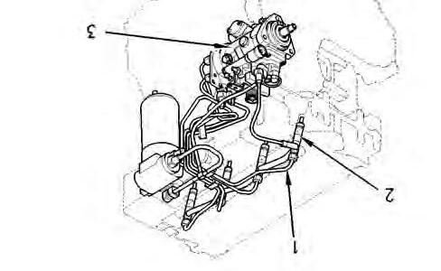
Removing fuel injection channels
1. Remove the front bonnet body.
2. Clean the injector cover, channels and parts close to the injectors to prevent impurities from entering the system.
3. Remove the injector cover (1) (Fig.1) by taking the screws (2) out of the cover plate.
4. Make indelible marks on the channel locations to make reassembly easier.
5. Disconnect the injection channels on the injector side.
6. Disconnect the injection channels on the injection pump side.
NOTE: Position a container to recover the fuel contained in the channels.
7. Disassemble or loosen the injection channel flanges. Remove the channels.
8. Plug the unions of the injection pump and injectors to keep dust out.
9. Also block the injection channels to keep dust out.
MA-03-03350A
Fig. 1
MA-03-03351A
Fig. 2
Perkins engine - Disassembling and reassembling
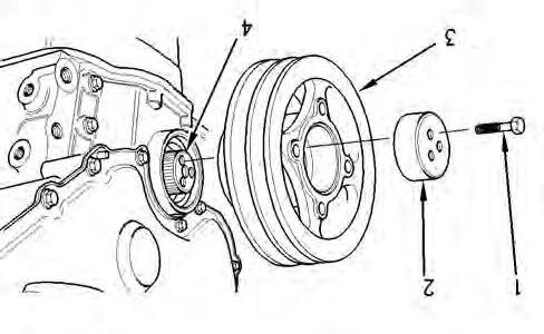
Removing the crankshaft pulley, fan and water pump
10. Loosen the alternator screws.
11. Release the belts by turning the alternator.
12. Take out the three screws (1) and the spacer (2) (Fig.3).
13. Remove the crankshaft pulley (3) (Fig.3).
14. Remove the fan. Take off the belts.
15. Drain the cooling system.
16. Loosen and remove the hoses attached to the water pump.
17. Remove the screws (3) from the pump (4) (Fig.4).
18. If required, gently tap the pump with a plastic hammer in order to release it.
19. Take off the water pump. Take off and discard the seal (2) (Fig.4).
Removing
the front cover plate
20. Remove the screws (3) (4) and (5) from the cover plate (1) (Fig.5).
NOTE: The screws are not identical. Mark them in relation to their holes in order to make reassembly easier.
21. Remove the cover plate (1). Take off and discard the seal (2) (Fig.5).
MA-03-03352A
Fig. 3
MA-03-03353A
Fig. 4
MA-03-03354A
Fig. 5
Perkins engine - Disassembling and reassembling
Refitting fuel injection channels
22. Check the condition of the channels (1) (Fig.2). Replace those that are defective.
23. Refit the injection channel flanges to hold the channels in place, without tightening.
24. Remove the dustproof plugs from the unions of the pipes and injection pump.
25. Reassemble the unions without tightening on either side of the injection channels.
26. Ensure that the channels fit correctly without being obstructed by other engine parts.
27. Tighten the channel flanges. Check their correct positioning again.
28. Tighten the channel / injector unions to 30Nm.
29. Tighten the channel / injection pump unions to 30Nm.
30. Bleed the system.
-Delphi DP210 pump: bleeding is automatic. Switch on the ignition for approximately 3 minutes. The air should bleed automatically from the system. Do not carry out steps 31 to 34
-Bosch VE10 pump: bleeding is not automatic. Perform steps 31 to 34
31. Switch on the ignition for 3 minutes then switch it off.
32. Loosen the injector unions.
33. Activate the starter until there is no air in the fuel flowing out of the injector unions (no bubbles).
34. Retighten the unions to 30 Nm.
35. Start the engine. Ensure it operates correctly and that there are no leaks.
36. Stop the engine.
37. Clean the internal surfaces of the injector cover.
38. Refit the injector cover (Fig.1).
39. Refit the screws. Tighten to a torque of 9 Nm.