
SHOP MANUAL CASE/INTERNATIONAL
MAGNUM SERIES
MODELS
7110-7120-7130-7140
IDENTIFICATION
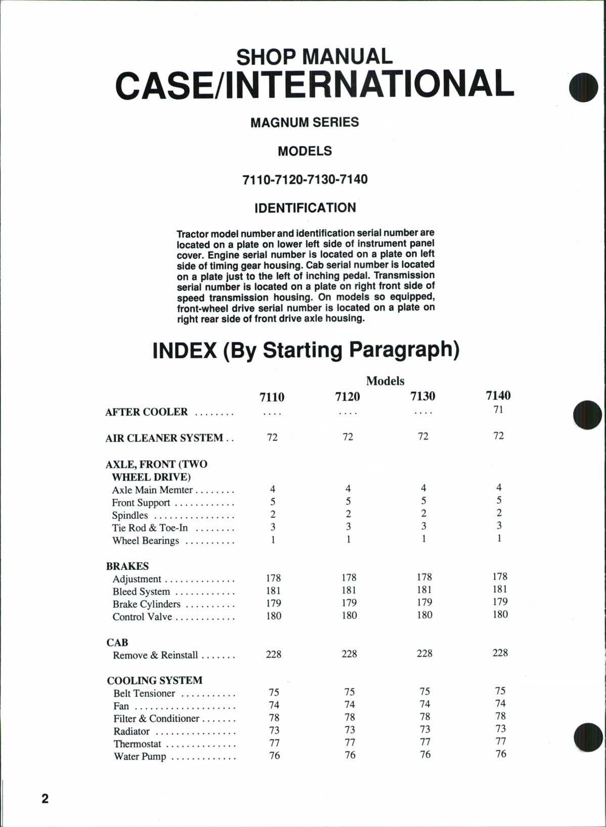
Tractor model number and identification seriai number are iocated on a piate on iower ieft side of instrument panei cover Engine seriai number is iocated on a piate on left side oftiming gear iiousing Cab seriai number is iocated on a piate just to the ieft of inching pedai Transmission seriai number is located on a piate on right front side of speed transmission housing. On modeis so equipped, front-wheei drive seriai number is iocated on a piate on right rear side offront drive axie housing.
INDEX (By Starting Paragraph)
CLICK HERE TO DOWNLOAD THE COMPLETE MANUAL
• Thank you very much for reading the preview of the manual.
• You can download the complete manual from: www.heydownloads.com by clicking the link below

• Please note: If there is no response to CLICKING the link, please download this PDF first and then click on it.
CLICK HERE TO DOWNLOAD THE
INDEX (CONT.)

INDEX (CONT.)
POWER TAKE-OFF
INDEX (CONT.)
Models
DUAL DIMENSIONS
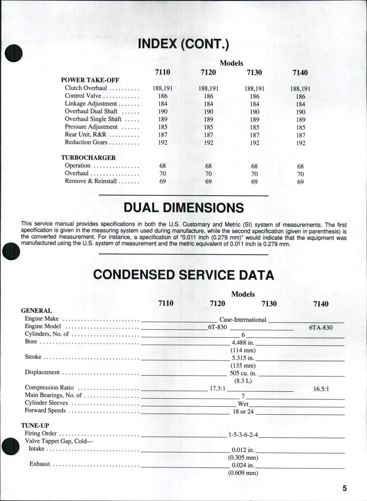
This service manual provides specifications in both the U.S. Customary and Metric (SI) system of measurements. The first specification is given in the measuring system used during manufacture, while the second specification (given in parenthesis) is the converted measurement For instance, a specification of "0.011 inch (0.279 mm)" would indicate that the equipment was manufactured using the U.S system of measurement and the metric equivalent of 0.011 inch is 0.279 mm
CONDENSED SERVICE DATA
Models
GENERAL
EngineMake _ ^Case-International^
EngineModel 6T-830 6TA-830
Cylinders,No.of 6
Bore 4.488in. (114mm)
Stroke 5.315in (135mm)
Displacement 505cuin (8.3L)
CompressionRatio 17.3:1 16.5:1
MainBearings,No.of 7
CylinderSleeves Wet
ForwardSpeeds 18or24 ^___
TUNE-UP
FiringOrder __^^_1-5-3-6-2-4.
ValveTappetGap,Cold-
Intake 0.012in. (0.305mm)
Exhaust 0.024in._ (0.609mm)
CONDENSED SERVICE DATA (CONT.)
TUNE-UP (CONT.)
InjectionPump
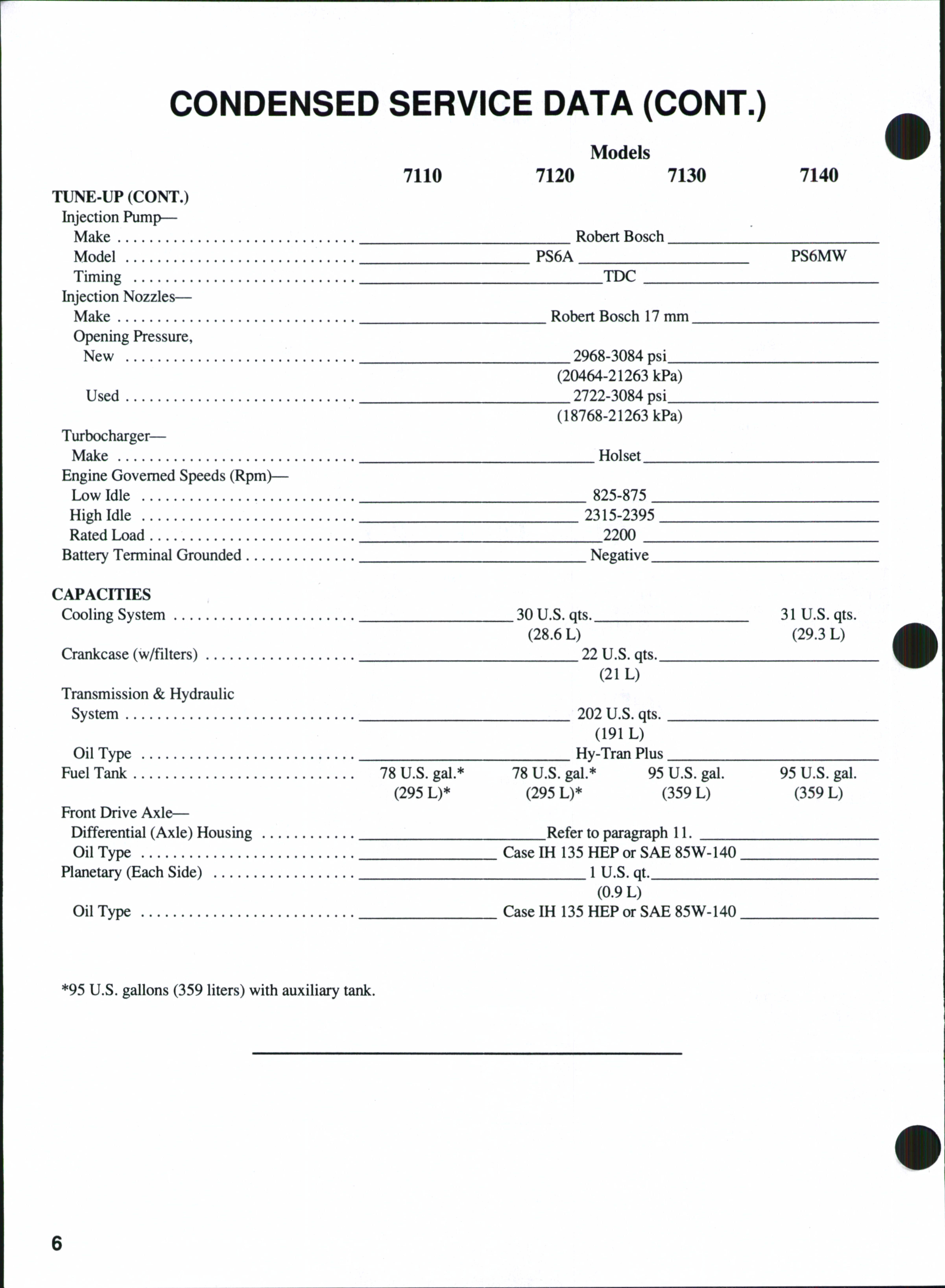
Make RobertBosch Model PS6A PS6MW Timing TDC
InjectionNozzles
Make RobertBosch17mm
OpeningPressure, New 2968-3084psi (20464-21263kPa) Used 2722-3084psi (18768-21263kPa)
Turbocharger
Make Holset
EngineGovernedSpeeds(Rpm)—
LowIdle 825-875
HighIdle 2315-2395
RatedLoad 2200
BatteryTerminalGrounded Negative
CAPACITIES
Crankcase(w/filters)
Transmission&Hydraulic System
OilType
(28.6L) (29.3L)
22U.Sqts (21L)
202U.S.qts. (191L)
FuelTank 78U.Sgal.*78U.Sgal.*95U.Sgal95U.Sgal (295L)* (295L)* (359L) (359L)
FrontDriveAxle
Differential(Axle)Housing Refertoparagraph11 OilType
Planetary(EachSide)
OilType
*95U.S.gallons(359liters)withauxiliarytank.
CaseIH135HEPorSAE85W-140
1U.S.qt. (0.9L)
CaseIH135HEPorSAE85W-140
FRONT AXLE (TWO-WHEEL DRIVE)
FRONT WHEEL BEARINGS
All Models
1 Refer to Fig 1 for typical wheel hub and bearing assembly Thetapered inner and outer roller bearings are not interchangeable Clean and inspect bearing cups and cones and renew as necessary
Install dust shield (2) outer flange toward hub and with open section on the bottom. Install oil seal (3)on the spindle (1) sothat metal face of seal is toward the hub. Press bearing cups (6) into hub until seated. Pack bearing cones (5 and 8) with No. 2 lithium grease and install bearing cone (5)in hub. Install hub wear ring (4)into hub until outer flange contacts hub. Coat lips of seal (3) with grease and install hub onto spindle. Install outer bearing cone (8),washer (9) and nut (10).Tighten nut to a torque of 15fl;.-lbs.(20N.m) while rotating hub. Back off nut to flrst slot where cotter pin can be installed. Install cotter pin and cap (12). Lubricate the assembly through lube fitting (13). Install wheel and tire assembly and tighten lug bolts to a torque of 140-160 ft.-lbs. (190-220 N.m).
SPINDLES
All Models
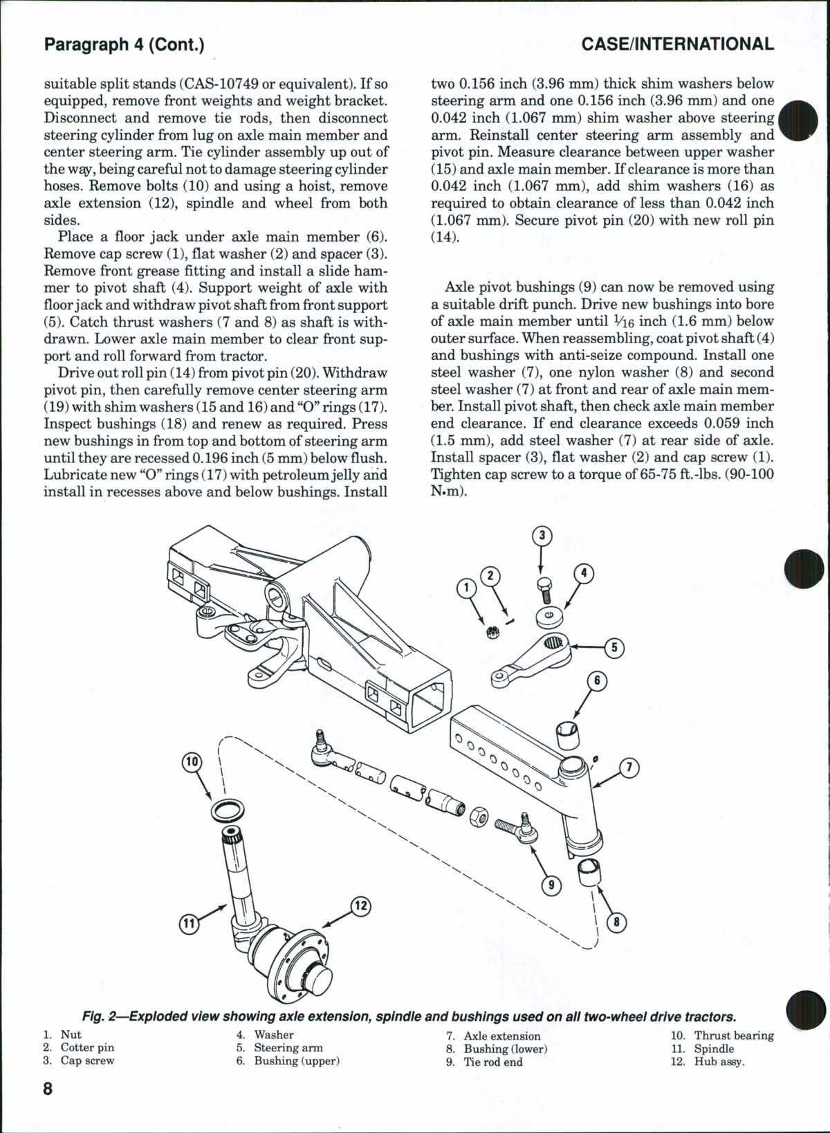
2. R&R SPINDLES. Ib remove either spindle, lift and support front of tractor and remove wheel. Disconnect tie rod balljoint (9—Fig 2)from steering arm (5). Remove cap screw (3) and washer (4). If not marked, install alignment punch marks on steering arm and spindle Remove steering arm (5) and lower spindle assembly (11)from axleextension (7) Remove thrust bearing (10) from spindle. Inspect spindle bushings (6 and 8) in axle extension and renew as necessary
If removed, install bushings (6 and 8) into axle extension with open end of oil grooves in bushings toward inside. Install bushings imtil recessed 0.157 inch (4 mm) below flush with top and bottom. New bushings are presized and should not require reaming if carefully installed.
Install thrust bearing (10) on spindle (11), then install spindle into axleextension.Alignpunch marks and install steering arm (5)on spindle Apply Loctite 262on threads ofcap screw (3), then install cap screw and washer (4) Connect tie rod end to steering arm and tighten nut (1) to a torque of 100 ft.-lbs. (136 N.m). Secure with cotter pin (2). Install wheel and tire assembly and tighten lug bolts to a torque of 140-160 ft.-lbs. (190-220 N.m). Lubricate with Case/IH 251EP or equivalent No 2 multipurpose lithium grease
TIE RODS AND TOE-IN
All Modeis
3 Removal and disassembly ofthe tie rods is obvious after examination ofthe xmitand reference toFig 2 Tighten tie rod end slotted nuts to a torque of 100 ft.-lbs. (136 N.m) and install new cotter pins Tighten clamp bolts to a torque of 40-50 ft.-lbs (55-70 N.m)
Front wheel toe-in must be 0.187-0.312 inch (4.77.9 mm).Ib adjust toe-in, remove clamp boltsfrom tie rod extension. Loosenjam nut, then rotate extension in or out to obtain correct toe-in. Install clamp bolts and tighten jam nut Recheck toe-in and readjust if necessary Both tie rods should be approximately the same length
AXLE MAIN MEMBER
All Models
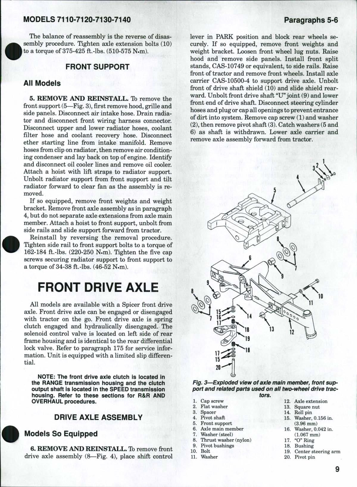
4.Tbremove the axlemain member (6—Fig. 3), first raise and support tractor under engine side rails with
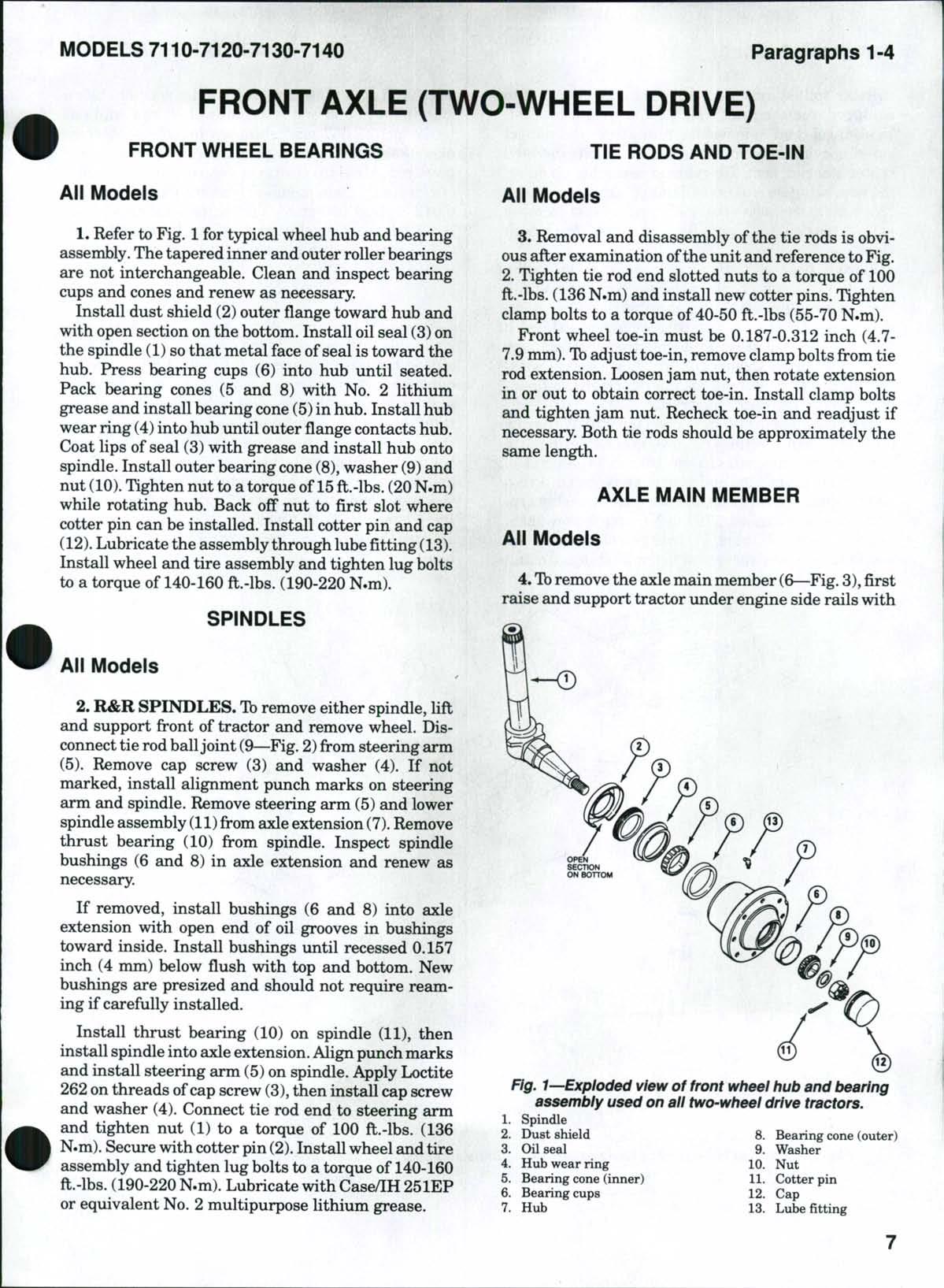
Fig. 1—Exploded view of front wheel hub and bearing assembly used on all two-wheel drive tractors.
Spindle
suitable split stands (CAS-10749 or equivalent). If so equipped, remove front weights and weight bracket. Disconnect and remove tie rods, then disconnect steering cylinder from lug on axle main member and center steering arm. Tie cylinder assembly up out of the way, beingcareful nottodamage steering cylinder hoses. Remove bolts (10) and using a hoist, remove axle extension (12), spindle and wheel from both sides.
Place a floor jack under axle main member (6). Remove cap screw (1), flat washer (2) and spacer (3). Remove front grease fitting and install a slide hammer to pivot shaft (4). Support weight of axle with floor jack and withdraw pivot shaft from front support (5). Catch thrust washers (7 and 8) as shaft is withdrawn. Lower axle main member to clearfi:'ontsupport and roll forward from tractor.
Drive out rollpin (14)from pivot pin (20) Withdraw pivot pin, then carefully remove center steering arm (19)with shimwashers (15and 16)and "O"rings(17) Inspect bushings (18) and renew as required Press new bushings in from top and bottom of steering arm until they are recessed 0.196 inch (5mm)below flush. Lubricate new "O" rings (17)with petroleumjelly arid install in recesses above and below bushings Install
two 0.156 inch (3.96 mm) thick shim washers below steering arm and one 0.156 inch (3.96 mm) and one 0.042 inch (1.067 mm) shim washer above steering arm. Reinstall center steering arm assembly and pivot pin. Measure clearance between upper washer (15) and axle main member. If clearance is more than 0.042 inch (1.067 mm), add shim washers (16) as required to obtain clearance of less than 0.042 inch (1.067 nmi). Secure pivot pin (20) with new roll pin (14).
Axle pivot bushings (9) can now be removed using a suitable drift punch Drive new bushings into bore of axle main member until Vie inch (1.6 mm) below outer surface When reassembling, coatpivot shaft (4) and bushings vdth anti-seize compound Install one steel washer (7), one nylon washer (8) and second steel washer (7) at front and rear of axle main member Install pivot shaft, then check axle main member end clearance If end clearance exceeds 0.059 inch (1.5 mm), add steel washer (7) at rear side of axle Install spacer (3), flat washer (2) and cap screw (1) Tighten cap screw to a torque of65-75 ft.-lbs. (90-100 N.m)
Fig, 2—Exploded view showing axie extension, spindie and bushings used on aii two-wheei drive tractors.
Nut
Washer
Axle extension
Thrust bearing
Cotter pin
Steering arm
Bushing (lower)
Spindle
Cap screw
Bushing (upper)
Tie rod end
The balance of reassembly is the reverse of disassembly procedure. Tighten axle extension bolts (10) to a torque of 375-425 ft.-lbs. (510-575 N.m).
FRONT SUPPORT
All Models
5. REMOVE AND REINSTALL. Tb remove the fi-ont support (5—Fig. 3), first remove hood, grille and side panels. Disconnect air intake hose. Drain radiator and disconnect front wiring harness connector. Disconnect upper and lower radiator hoses, coolant filter hose and coolant recovery hose. Disconnect ether starting line from intake manifold. Remove hoses from cliponradiator, then remove air conditioning condenser and lay back on top of engine. Identify and disconnect oil cooler lines and remove oil cooler. Attach a hoist with lift straps to radiator support. Unbolt radiator support from front support and tilt radiator forward to clear fan as the assembly is removed
If so equipped, remove front weights and weight bracket Remove front axle assembly as in paragraph 4, but do not separate axle extensions from axle main member Attach a hoist to front support, unbolt from side rails and slide support forward from tractor Reinstall by reversing the removal procedure Tighten side rail to front support bolts to a torque of 162-184 ft.-lbs. (220-250 N.m) Tighten the five cap screws securing radiator support to firont support to a torque of 34-38 ft.-lbs. (46-52 N.m)
FRONT DRIVE AXLE
All models are available with a Spicer front drive axle. Front drive axle can be engaged or disengaged with tractor on the go. Front drive axle is spring clutch engaged £ind hydraulically disengaged. The solenoid control valve is located on left side of rear frame housing and is identical to the rear differential lock valve Refer to paragraph 175 for service information. Unit is equipped with a limited slip differential.
NOTE: The front drive axle clutch is located in the RANGE transmission iiousing and the ciutch output shaft is iocated in the SPEED transmission housing. Refer to these sections for R&R AND OVERHAUL procedures.
DRIVE AXLE ASSEMBLY
Models So Equipped
6. REMOVE AND REINSTALL. Tbremove fi-ont drive axle assembly (8—Fig. 4), place shift control
lever in PARK position and block rear wheels securely If so equipped, remove front weights and weight bracket Loosen front wheel lug nuts Raise hood and remove side panels. Install front split stands, CAS-10749 or equivalent, to side rails. Raise front oftractor and removefi-ontwheels. Install axle carrier CAS-10500-4 to support drive axle. Unbolt front of drive shaft shield (10) and slide shield rearward. Unbolt front drive shaft "U"joint (9) and lower front end of drive shaft. Disconnect steering cylinder hoses and plugor capallopenings toprevent entrance ofdirt into system. Remove cap screw (1) and washer (2),then remove pivot shaft (3). Catch washers (5 and 6) as shaft is withdrawn. Lower axle carrier and remove axle assembly forward from tractor.
Fig. 3 Expioded view of axie main member, front support and reiated parts used on aii two-wheei drive tractors,
Cap screw
Axle extension
Flat washer
Washer (steel) (1.067 mm)
Thrust washer (nylon)
"O" Ring
Inspect bushings (7)and renew as necessary When installing new bushings, apply a coat of Loctite antiseize to bore in axle housing. Freeze bushings in dry ice and carefully install flush to Vie inch (1.6 mm) below the face of axle housing.
Inspect thrust washers (5and 6)for excessive wear and renew as necessary Reinstall axle assembly to front support Make sure that nylon thrust washer (6) is installed between steel thrust washers (5) at both front and rear sides of axle Use as many additional steel washers as possible at rear side of axle housing to shim axle housing forward Secure pivot shaft (3) in place with washer (2) and cap screw (1), tightened to a torque of 93-112 ft.-lbs. (126-152 N.m) Connect steering cylinder lines and reinstall front drive shaft Tighten drive shaft coupling bolts to a torque of45-54 ft.-lbs. (61-73 N.m) Install fi-ont drive shaft shield Remove axle carrier. Install front wheels and remove split standsfif-omside rails. Tighten front wheel lug nuts to a torque of 300-370 ft.-lbs. (407-502 N.m). If so equipped, install front weight bracket and tighten cap screws to a torque of 450-540 ft.-lbs. (610-730 N.m), then install front weights.

FRONT SUPPORT
Models So Equipped
7. REMOVE AND REINSTALL. Tbremove fi^ont support (4—Fig 4), first remove hood, grille and side panels Disconnect air intake hose Drain radiator and disconnect front wiring harness connector Disconnect upper and lower radiator hoses, coolant air bleed hose and coolant recovery hose Disconnect ether starting line from intake manifold Remove hoses from cliponradiator, then remove air conditioning condenser and lay back on top of engine Identify and disconnect oil cooler lines and remove oil cooler Attach a hoist with lift straps to radiator support Unbolt radiator support from front support and tilt radiator forward to clear fan as the assembly is removed
If so equipped, remove front weights and weight bracket Remove front drive axle assembly as outlined in paragraph 6 Attach a hoist to front support, unbolt from side rails and slide front support forward from tractor.
Reinstall by reversing removal procedure Tighten side rail to front support bolts to a torque of 162-184 ft.-lbs. (220-250 N.m). Tighten the five cap screws securing radiator support to front support to a torque of 34-38 ft.-lbs. (46-52 N.m).
TIE ROD AND TOE-iN
Models So Equipped
8. Due to the closeness between tie rod andfiront support, removal oftie rod and toe-in adjustment can be accomplished only after removal offront drive axle assembly as outlined in paragraph 6 Disassembly of tie rod is obvious after removal and reference to Fig 5.Tbe-in should be adjusted to 0-0.5 inch (0-12.7mm). One full turn ofa tie rod end (2 or 6) will change toe-in % inch (9.5 mm). Make sure bow of tie rod tube (4) is down
Tighten slotted nuts (1) to a torque of 140 ft.-lbs. (190 N.m) Tighten jam nuts (3 and 5) to a torque of 250-300 ft.-lbs. (340-405 N.m)
WHEEL HUB AND PLANETARY
Modeis So Equipped
9. R&R AND OVERHAUL, Tb remove the wheel hub and planetary, support axle housing and remove front wheel and tire assembly Rotate wheel hub until drain plug (13—Fig. 6) is at bottom.
NOTE: Front drive shaft must be disconnected before wheei hub can be rotated.
Fig. 4^-View of front drive axie and front support removed from tractor.
CLICK HERE TO DOWNLOAD THE COMPLETE MANUAL
• Thank you very much for reading the preview of the manual.
• You can download the complete manual from: www.heydownloads.com by clicking the link below
• Please note: If there is no response to CLICKING the link, please download this PDF first and then click on it.
CLICK HERE TO DOWNLOAD THE
Remove drain plug and allow oil to drain Remove the two socket head cap screws (14), then remove planetary carrier (12) Withdraw sun gear (11) Removethe three cap screws(10),retaining plate (9)and shim (8), then lift off ring gear (21) Remove wheel hub (4) Remove bearing cone (6)fii^omring gear (21) Remove oil seal (1), inner bearing cone (2), "O" ring (7) and, if necessary, bearing cups (3 and 5) from wheel hub (4)
Remove retaining rings (20), spacers (16) and planetary gears (18) with needle rollers (17) and spacers (19). Clean and inspect all parts and renew as necessary. Needle rollers (17) are available in a set of 376 and planetary gears (18) are available in a set of four.
Install first spacer plate (16) over pin in planetary carrier (12) Use petroleumjelly to hold needle rollers in place and install two rows of needle rollers in gear (18) with spacer (19) between the two rows Install planetary gear and needle roller assembly over pin in planetary carrier When all four plsmetary gears and needle rollers are installed, install second spacer plate (16) and secure with retaining rings (20) If removed, install bearing cups (3 and 5) in hub
Heat bearing cone (6) in a bearing oven to a temperature of 250° F (120° C) and install on ring gear (21) until seated
WARNING: Always wear heat protective gioves when handiing heated parts
Install bearing cone (2), but do not install oil seal (1) at this time. Install Hub (2) on pivot housing and install ring gear (21) and retaining plate (9) without shims (8) Tighten cap screws (10) evenly to a torque
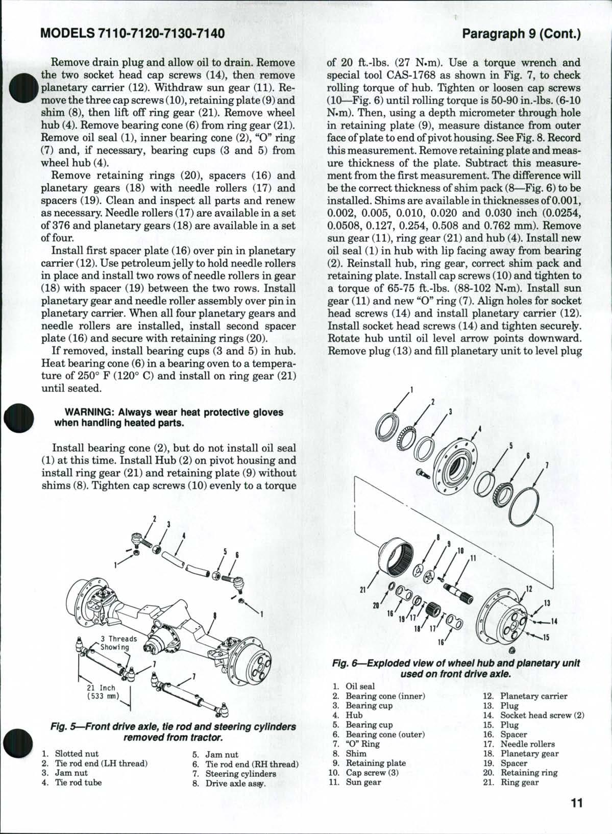
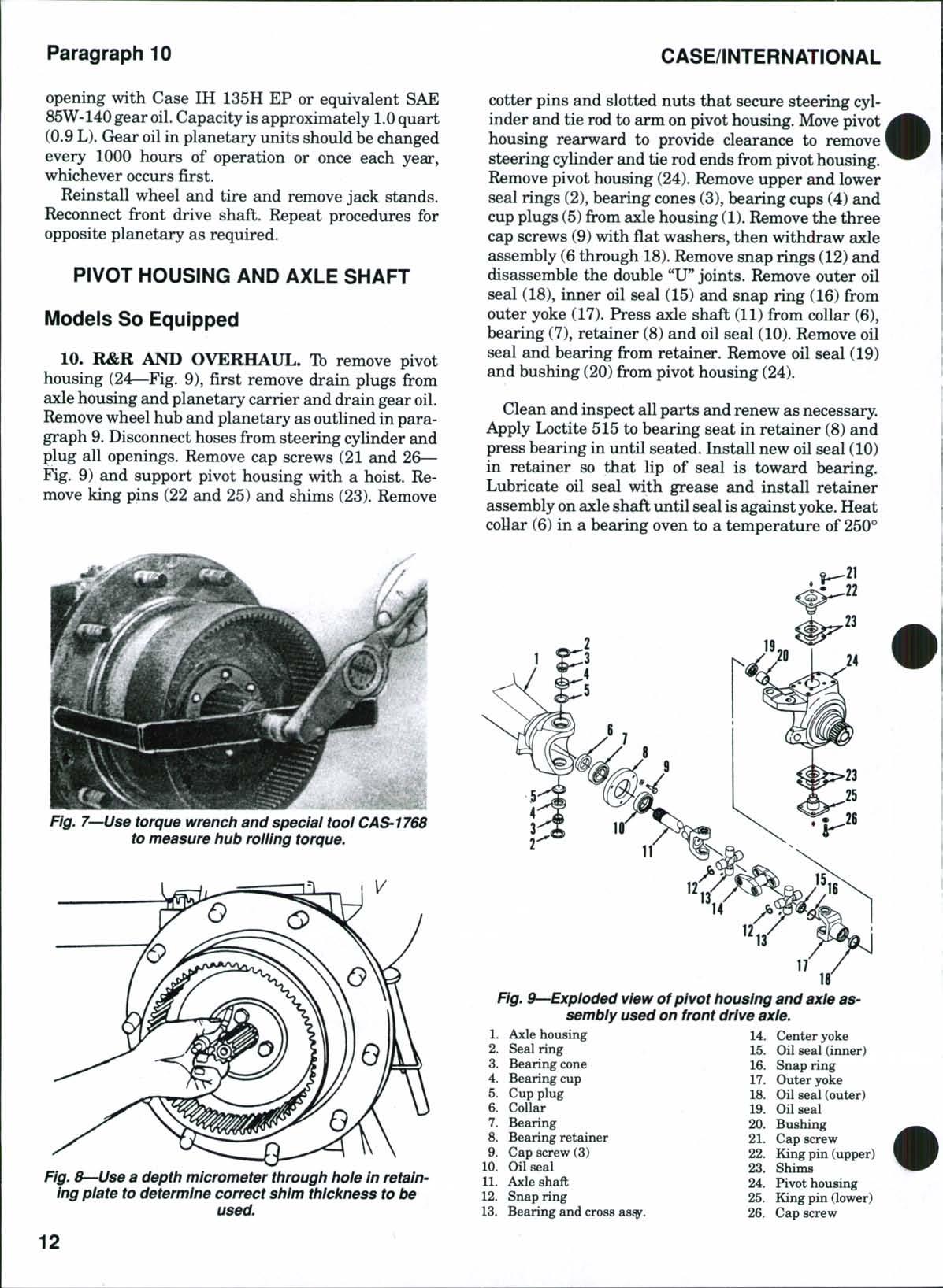
of 20 ft.-lbs. (27 N.m). Use a torque wrench and special tool CAS-1768 as shown in Fig. 7, to check rolling torque of hub. Tighten or loosen cap screws (10—Fig. 6) until rolling torque is 50-90 in.-lbs. (6-10 N.m). Then, using a depth micrometer through hole in retaining plate (9), measure distance from outer face ofplate to end ofpivothousing. SeeFig. 8.Record this measurement. Removeretaining plate and measure thickness of the plate. Subtract this measurement from the first measurement. The difference will be the correct thickness of shim pack (8—Fig. 6) to be installed. Shims are available in thicknesses of0.001, 0.002, 0.005, 0.010, 0.020 and 0.030 inch (0.0254, 0.0508, 0.127, 0.254, 0.508 and 0.762 mm). Remove sun gear (11), ring gear (21) and hub (4). Install new oil seal (1) in hub with lip facing away from bearing (2). Reinstall hub, ring gear, correct shim pack and retaining plate. Install cap screws (10) and tighten to a torque of 65-75 ft.-lbs. (88-102 N.m). Install sun gear (11) and new "O" ring (7). Align holes for socket head screws (14) and install planetary carrier (12). Install socket head screws (14) and tighten secure^. Rotate hub until oil level arrow points downward. Remove plug (13) and fill planetary unit to level plug
Fig. S—Front drive axle, tie rod and steering cylinders removed from tractor.
Slotted nut
Fig. &--Expioded view of wheei hub and pianetary unit used on front drive axie.
1. Oil seal
Bearing cone (inner)
Bearing cup
Hub
Bearing cup
Bearing cone (outer)
"O"Ring
Shim
Retaining plate
Cap screw (3)
Sun gear
Planetary carrier
Plug
Socket head screw (2)
Plug
Spacer
Needle rollers
Planetary gear
Spacer
Retaining ring
Ring gear
opening with Case IH 135H EP or equivalent SAE 85W-140gear oil Capacity isapproximately 1.0 quart (0.9 L) Gear oil in planetary units should be changed every 1000 hours of operation or once each year, whichever occurs first.
Reinstall wheel and tire and remove jack stands. Reconnect front drive shaft. Repeat procedures for opposite planetary as required.
PIVOT HOUSING AND AXLE SHAFT
Modeis So Equipped
10. R&R AND OVERHAUL. Tb remove pivot housing (24—Fig 9), first remove drain plugs from axle housing and planetary carrier and drain gear oil Remove wheel hub and planetary as outlined in paragraph 9 Disconnect hoses from steering cylinder and plug all openings Remove cap screws (21 and 26 Fig 9) and support pivot housing with a hoist Remove king pins (22 and 25) and shims (23) Remove
cotter pins and slotted nuts that secure steering cylinder and tie rod to arm on pivot housing. Move pivot housing rearward to provide clearance to remove stoedng cylinder and tie rod ends from pivot housing. Remove pivot housing (24). Remove upper and lower seal rings (2), bearing cones (3), bearing cups (4) and cup plugs (5)from axle housing (1). Remove the three cap screws (9) with flat washers, then withdraw axle assembly (6 through 18).Remove snap rings (12) and disassemble the double "U" joints. Remove outer oil seal (18), inner oil seal (15) and snap ring (16) from outer yoke (17). Press axle shaft (11) from collar (6), bearing (7), retainer (8) and oil seal (10). Remove oil seal and bearing from retainer. Remove oil seal (19) and bushing (20) from pivot housing (24).
Clean and inspect all parts and renew as necessary Apply Loctite 515 to bearing seat in retainer (8) and press bearing in until seated. Install new oil seal (10) in retainer so that lip of seal is toward bearing. Lubricate oil seal with grease and install retainer assembly on axleshaft until seal is against yoke Heat collar (6) in a bearing oven to a temperature of 250°
Fig. 7—Use torque wrench and speciai tooi CAS-1768 to measure hub roiiing torque.
Fig. 8—Use a depth micrometer through hole in retaining piate to determine correct shim thicicness to be used.
Fig. 9—Expioded view of pivot housing and axie assembiy used on front drive axie.
F (120° C) and install collar onto axle shaft until firmly against bearing (7)
WARNING: Aiways wear heat protective gloves when handiing heated parts.
Install bushing (20) and oil seal (19) in pivot housing so that lip of seal is toward bushing. Install retaining ring (16), inner oil seal (15) and outer oil seal (18) in outer yoke (17) as shown in Fig. 10. Reassemble double *TJ"joints and yokes, then install axle assembly (6 through 18—Fig. 9). Apply Loctite 515 to threads of cap screws (9), install cap screws and fiat washers and tighten to a torque of 35-45 ft.-lbs. (47-61 N.m). Apply Loctite 515 to lips of cup plugs (5),then install cup plugs and bearing cups (4) in axlehousing.Lubricate bearing cones(3)with Case IH 25IH EPor equivalent No.2multipurpose lithium grease and install bearing cones. Do not install seal rings (2) at this time. Install pivot housing (24) over axle housing (1). Do not install tie rod or steering cylinder. Install lower king pin (25) with 0.015 inch (0.381mm) thick shim pack (23). Tighten cap screws (26) with washers, alternately and evenly to a torque of 80-90 ft.-lbs. (108-122 N.m). Install upper king pin (22)with 0.015 inch (0.381 mm)thick shim pack (23). Tighten cap screws (21) with washers, alternately and evenly to a torque of80-90 ft.-lbs. (108-122N.m).
Using a torque wrench on one of the upper king pin cap screws (21), check the amount of torque required to move the pivot housing. The torque must be between 16and 25 ft.-lbs. (22 and 34N.m). If necessary, add shims to decrease torque or remove shims to increase torque. Shims are available in thicknesses of0.005 and 0.010 inch (0.127-0.254 mm). Upper and lower king pins must be shimmed evenly.
Unbolt and remove upper and lower king pins and shim packs Move pivot housing as required to install new seal rings (2) and to connect steering cylinder and tie rod ends Apply Loctite anti-seize to king pins, then reinstall king pins with correct shim packs Tighten cap screws (21 and 26) to a torque of 80-90 ft.-lbs. (108-122 N.m) Tighten slotted nuts on steering cylinder and tie rod ends to a torque of 140 ft.-lbs. (190 N.m) and secure with new cotter pins
Refer to paragraph 9for balance ofreassembly Fill axle housing to level plugopeningwith recommended gear oil Refer to paragraph 11 for capacity
DIFFERENTIAL AND BEVEL GEARS
Modeis So Equipped
11. R&R AND OVERHAUL. Tbremove the front differential assembly, place transmission lever in PARK position and securely block rear wheels. Remove front drive axle assembly as outlined in paragraph 6, then remove both planetary and hub
assemblies as in paragraph 9 and pivot housings and axles as in paragraph 10. Support the differential carrier assembly with a hoist, unbolt carrier from axle housing and remove the assembly. Place unit on a clean bench.
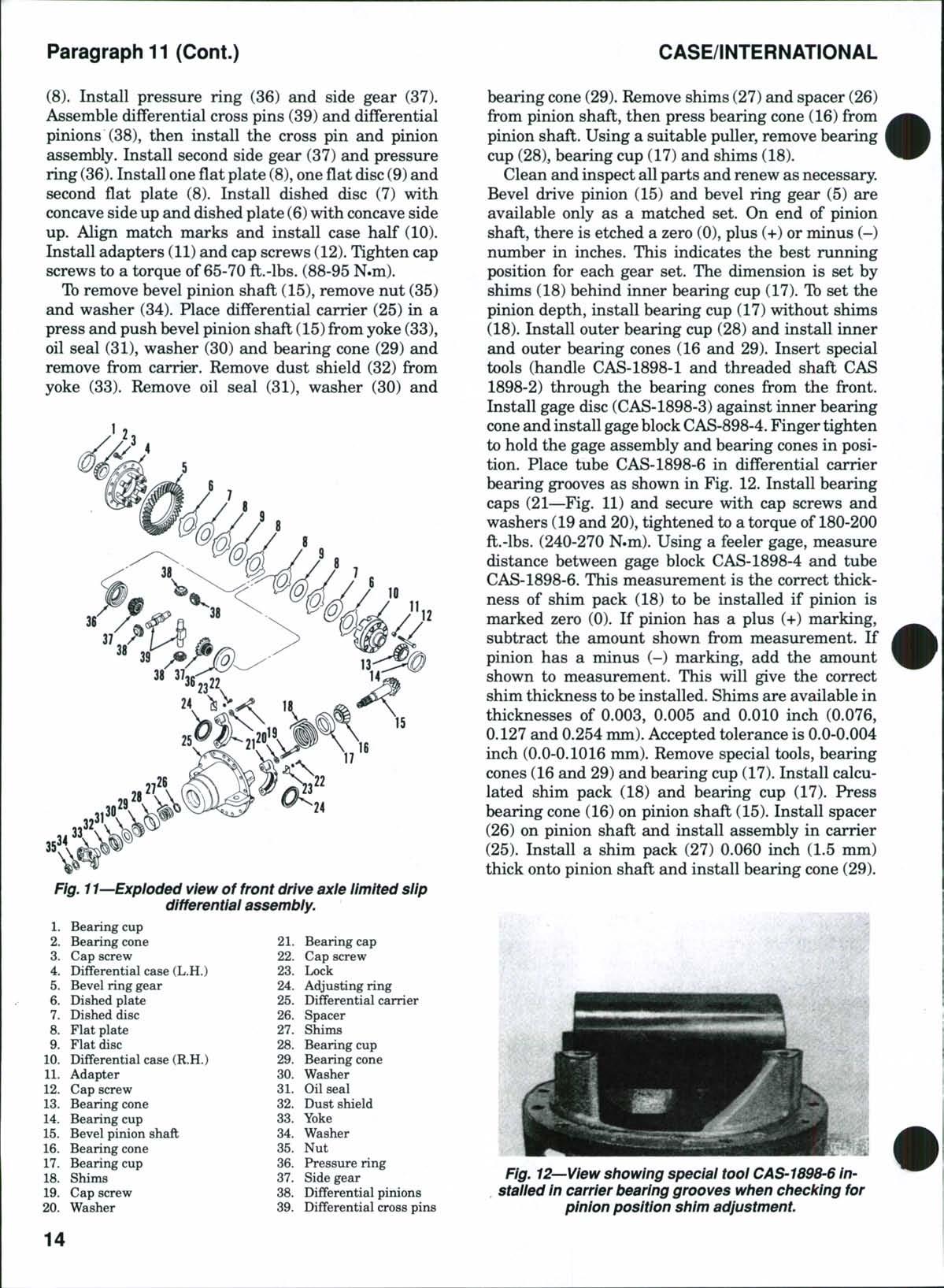
Tb disassemble the differential assembly, refer to Fig 11 and remove capscrews(22),washers and locks (23) Remove cap screws (19),washers (20) and bearingcaps (21)with adjusting rings (24) Separate bevel ring gear and differential case from carrier Remove bearing cups (1 and 14) Place match marks across differential casehalves (4 and 10) Remove cap screws (12) and adapters (11) and lift off case half (10) Remove cap screws (12) and adapters (11) and lift off case half (10) Remove dished plate (6), dished disc (7), fiat plates (8) and fiat disc (9) Remove pressure ring (36) and side gear (37), then lift out cross pins (39) and differential pinions (38) Remove side gear (37), pressure ring (36), fiat plates (8), fiat disc (9), dished disc (7) and dished plate (6)from left case half (4) Remove cap screws (3) and separate bevel ring gear (5) from case half (4) Using a suitable puller, remove bearing cones (2 and 13)
Clean and inspect all parts and renew as necessary Bevel ring gear (5) and bevel pinion shaft (15) are available only as a matched set When reassembling, heat bearing cones (2 and 13) in a bearing oven to a temperature of 250° F (120° C) and install on case halves (4 and 10)
WARNING: Aiways wear heat protective gioves when handiing heated parts
Assemble bevel ring gear (5) to case half (4), then install and tighten retaining capscrews(3)toa torque of 100-120 ft.-lbs. (135-162 N.m). Apply a coat of friction modifier (Case IH part number 990063R2) to all disc and plate friction surfaces Place case half (4) assembly on a bench with bevel ring gear facing up Install dished plate (6) with concave side down Install dished disc (7) with concave side down. Install oneflat plate (8),oneflat disc(9)and second flat Plate
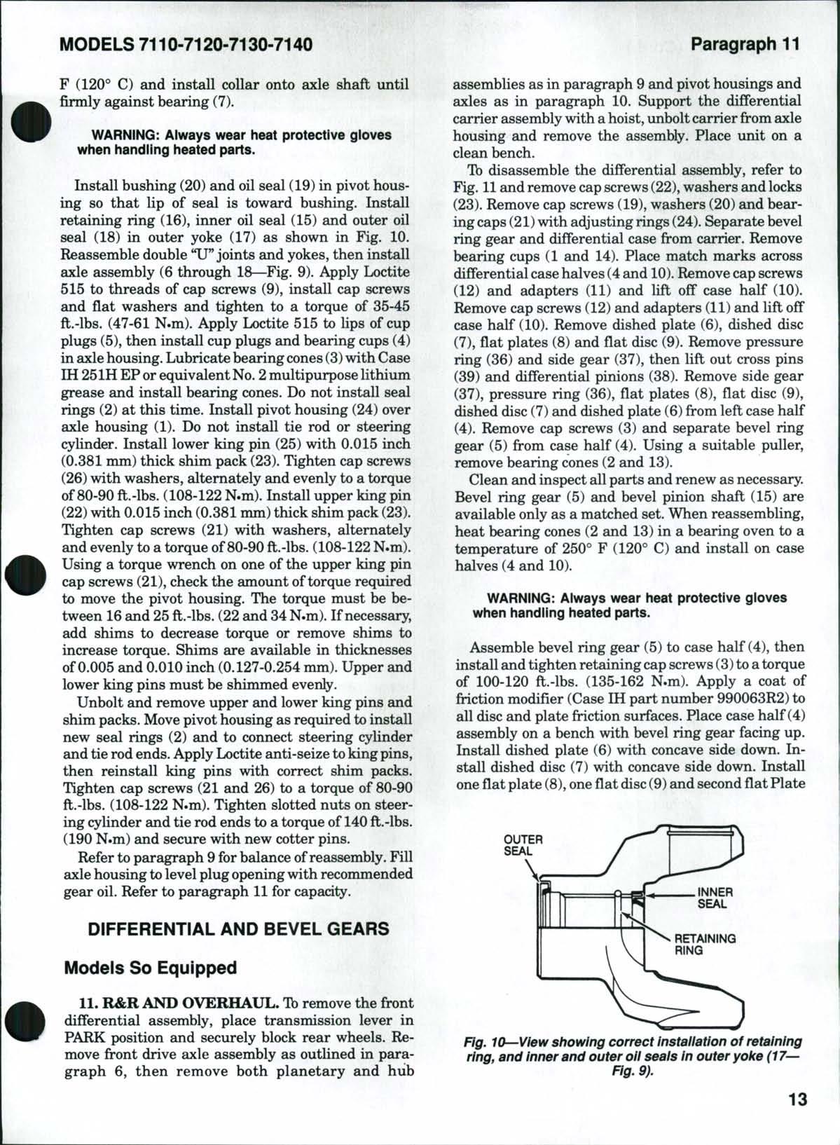
Fig^ 10--View showing correct instaiiation of retaining ring, and inner and outer oil seals in outer yoke (17— Fig. 9).
OUTER SEAL
(8) Install pressure ring (36) and side gear (37) Assemble differential cross pins (39) and differential pinions (38), then install the cross pin and pinion assembly Install second side gear (37) and pressure ring (36) Install one fiat plate (8), oneflat disc(9) and second fiat plate (8) Install dished disc (7) with concave sideup and dished plate (6)with concave side up Align match marks and install case half (10) Install adapters (11)and cap screws (12) Tighten cap screws to a torque of 65-70 ft.-lbs. (88-95N.m)
Tbremove bevel pinion shaft (15), remove nut (35) and washer (34). Place differential carrier (25) in a press and push bevel pinion shaft (15)from yoke (33), oil seal (31), washer (30) and bearing cone (29) and remove from carrier. Remove dust shield (32) from yoke (33). Remove oil seal (31), washer (30) and
37 Side gear
38 Differential pinions
39 Differential cross pins
bearing cone (29) Remove shims (27) and spacer (26) from pinion shaft, then press bearing cone (16) from pinion shaft Using a suitable puller, remove bearing cup (28), bearing cup (17) and shims (18)
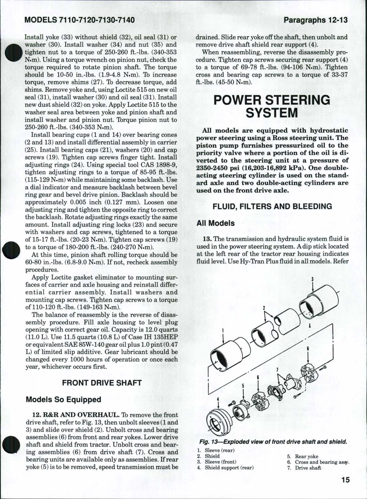
Clean and inspect all parts and renew as necessary. Bevel drive pinion (15) and bevel ring gear (5) are available only as a matched set. On end of pinion shaft, there is etched a zero (0), plus (+) or minus (-) nimiber in inches. This indicates the best running position for each gear set. The dimension is set by shims (18) behind inner bearing cup (17). Tb set the pinion depth, install bearing cup (17) without shims (18). Install outer bearing cup (28) and install inner and outer bearing cones (16 and 29). Insert special tools (handle CAS-1898-1 and threaded shaft CAS 1898-2) through the bearing cones from the front. Install gage disc (CAS-1898-3) against inner bearing coneand install gageblockCAS-898-4. Finger tighten to hold the gage assembly and bearing cones in position. Place tube CAS-1898-6 in differential carrier bearing grooves as shown in Fig. 12. Install bearing caps (21—Fig. 11) and secure with cap screws and washers (19 and 20),tightened to a torque of 180-200 ft.-lbs. (240-270 N.m). Using a feeler gage, measure distance between gage block CAS-1898-4 and tube CAS-1898-6. This measurement is the correct thickness of shim pack (18) to be installed if pinion is marked zero (0). If pinion has a plus (+) marking, subtract the amount shown fi:'om measurement. If pinion has a minus (-) marking, add the amount shown to measurement. This will give the correct shim thickness to be installed. Shims are available in thicknesses of 0.003, 0.005 and 0.010 inch (0.076, 0.127 and 0.254 mm).Accepted tolerance is 0.0-0.004 inch (0.0-0.1016 mm). Remove special tools, bearing cones (16 and 29) and bearing cup (17). Install calculatod shim pack (18) and bearing cup (17). Press bearing cone (16) on pinion shaft (15). Install spacer (26) on pinion shaft and install assembly in carrier (25). Install a shim pack (27) 0.060 inch (1.5 mm) thick onto pinion shaft and install bearing cone (29).
Fig. 12—View showing speciai tooi CAS-1898-6 instaiied in carrier bearing grooves when checking for pinion position shim adjustment.
Install yoke (33) without shield (32), oil seal (31) or washer (30). Install washer (34) and nut (35) and tighten nut to a torque of 250-260 ft.-lbs. (340-353 N.m). Using a torque wrench onpinion nut, check the torque required to rotate pinion shaft. The torque should be 10-50 in.-lbs. (1.9-4.8 N.m). Tb increase torque, remove shims (27). Tb decrease torque, add shims. Remove yoke and, using Loctite 515on new oil seal (31), install washer (30) and oil seal (31). Install new dust shield (32) on yoke. Apply Loctite 515to the washer seal area between yoke and pinion shaft and install washer aind pinion nut. Tbrque pinion nut to 250-260 ft.-lbs. (340-353 N.m).
Install bearing cups (1 and 14) over bearing cones (2 and 13) and install differential assembly in carrier (25) Install bearing caps (21), washers (20) and cap screws (19) Tighten cap screws finger tight Install adjusting rings (24) Using special tool CAS 1898-9, tighten adjusting rings to a torque of 85-95 ft.-lbs. (115-129N.m)while maintaining somebacklash Use a dial indicator and measure backlash between bevel ring gear and bevel drive pinion Backlash should be approximately 0.005 inch (0.127 mm) Loosen one adjusting ring and tighten the opposite ring to correct the backlash Rotate adjusting rings exactly the same amount Install adjusting ring locks (23) and secure with washers and cap screws, tightened to a torque of 15-17 ft.-lbs. (20-23 N.m).Tighten cap screws (19) to a torque of 180-200 ft.-lbs. (240-270 N.m).
At this time, pinion shaft rolling torque should be 60-80 in.-lbs (6.8-9.0 N.m) If not, recheck assembly procedures
Apply Loctite gasket eliminator to mounting surfaces of carrier and axle housing and reinstall differential carrier assembly Install washers and mounting cap screws Tighten cap screws to a torque of 110-120 ft.-lbs. (149-163 N.m)
The balance of reassembly is the reverse of disassembly procedure Fill axle housing to level plug opening with correct gear oil. Capacity is 12.0 quarts (11.0 L).Use 11.5 quarts (10.8 L) of Case IH 135HEP orequivalent SAE85W-140gear oilplus 1.0 pint (0.47 L) of limited slip additive. Gear lubricant should be changed every 1000 hours of operation or once each year, whichever occurs first.
FRONT DRiVE SHAFT
Modeis So Equipped
12. R&R AND OVERHAUL. Tbremove the front drive shaft, refer to Fig 13,then unbolt sleeves (1and 3) and slide over shield (2). Unbolt cross and bearing assemblies (6) from front and rear yokes. Lower drive shaft and shield from tractor. Unbolt cross and bearing assemblies (6) from drive shaft (7). Cross and bearing units are available only as assemblies If rear yoke (5)isto be removed, speed transmission must be
drained Slide rear yoke off the shaft, then unbolt and remove drive shaft shield rear support (4) When reassembling, reverse the disassembly procedure Tighten cap screws securing rear support (4) to a torque of 69-78 ft.-lbs. (94-106 N.m) Tighten cross and bearing cap screws to a torque of 33-37 ft.-lbs. (45-50 N.m)
POWER STEERING SYSTEM
All models are equipped with hydrostatic power steering using a Ross steering unit. The piston pump furnishes pressurized oil to the priority valve where a portion of the oil is diverted to the steering unit at a pressure of 2350-2450 psi (16,203-16,892 kPa). One doubleacting steering cylinder is used on the standard axle and two double-acting cylinders are used on the front drive axle.
FLUID, FiLTERS AND BLEEDiNG
Aii Modeis
13. The transmission and hydraulic system fluid is used in the power steering system. Adip stick located at the left rear of the tractor rear housing indicates fiuid level UseHy-Tran Plus fiuid in allmodels Refer
Fig.
to CONDENSED SERVICE DATA for reservoir capacity and to HYDRAULIC SYSTEM SECTION for additional hydraulic system information. A suction screen-type filter is located in right side of range transmission housing and an externally mounted pressure screw-on-type filter is located on right side of transmission See Fig 14 Tb clean filter screen (13), first drain transmission housing, then remove plug and drain filter base (12) Unbolt and remove cover (17) with "O" ring (16), screen locator (15) with "O"ring (14) and withdraw screen (13). Clean screen in suitable solvent and blow dry with compressed air. When reinstalling, install screen with gasket end outward Lubricate new "O" rings (14 and 16) with petroleum jelly and install with screen locator (15) and cover (17). Install and tighten cover cap screws. Install drain plugs and refill transmission to dip stick "FULL" level.
The manufacturer recommends that transmission and hydraulic fluid be drained and new Hy-Tran Plus fluid be installed each 1000 hours of operation Suction filter screen should be removed, cleaned and reinstalled each 1000 hours of operation Filter element (5) should bechanged whenever service monitor ondigital instrument cluster indicates aclogged filter or at least once each 1000 hours of operation
Tb change the filter element (5), unbolt and remove filter shield. Using a strap wrench, rotate filter element counterclockwise to remove. Lubricate gasket on new element with clean oil and install element
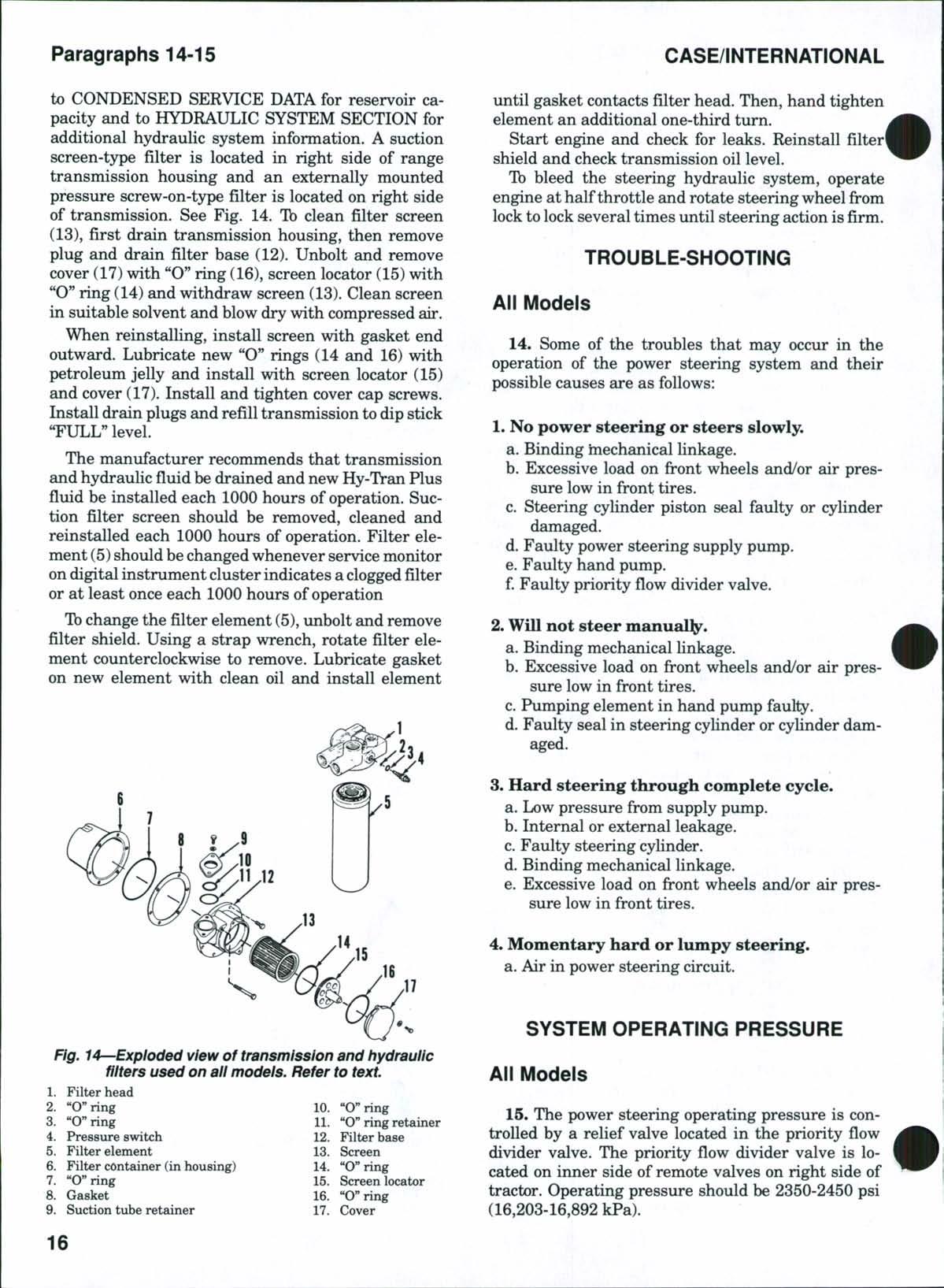
until gasket contacts filter head Then, hand tighten element an additional one-third turn
Start engine and check for leaks Reinstall filter' shield and check transmission oil level
Tb bleed the steering hydraulic system, operate engine at half throttle and rotate steering wheel from lock to lock several times until steering action is firm.
TROUBLE-SHOOTING
All Models
14. Some of the troubles that may occur in the operation of the power steering system and their possible causes are as follows:
1. No power steering or steers slowly.
a Binding hiechanical linkage
b Excessive load on front wheels and/or air pressure low in front tires
c Steering cylinder piston seal faulty or cylinder damaged
d Faulty power steering supply pump
e Faulty hand pump
f Faulty priority flow divider valve
2. Will not steer manual^.
a Binding mechanical linkage
b Excessive load on front wheels and/or air pressure low in front tires
c Pumping element in hand pump faulty
d Faulty seal in steering cylinder or cylinder damaged
3. Hard steering through complete cycle.
a Low pressure from supply pump
b Internal or external leakage
c Faulty steering cylinder
d Binding mechanical linkage
e Excessive load on front wheels and/or air pressure low in front tires
4. Momentary hard or lumpy steering.
a Air in power stoering circuit
SYSTEM OPERATiNG PRESSURE
Aii Modeis
15. The power steering operating pressure is controlled by a relief valve located in the priority flow divider valve The priority flow divider valve is located on inner side of remote valves on right side of tractor. Operating pressure should be 2350-2450 psi (16,203-16,892 kPa)
Fig. 14^-Expioded view of transmission and hydraulic niters used on aii modeis. Refer to text.
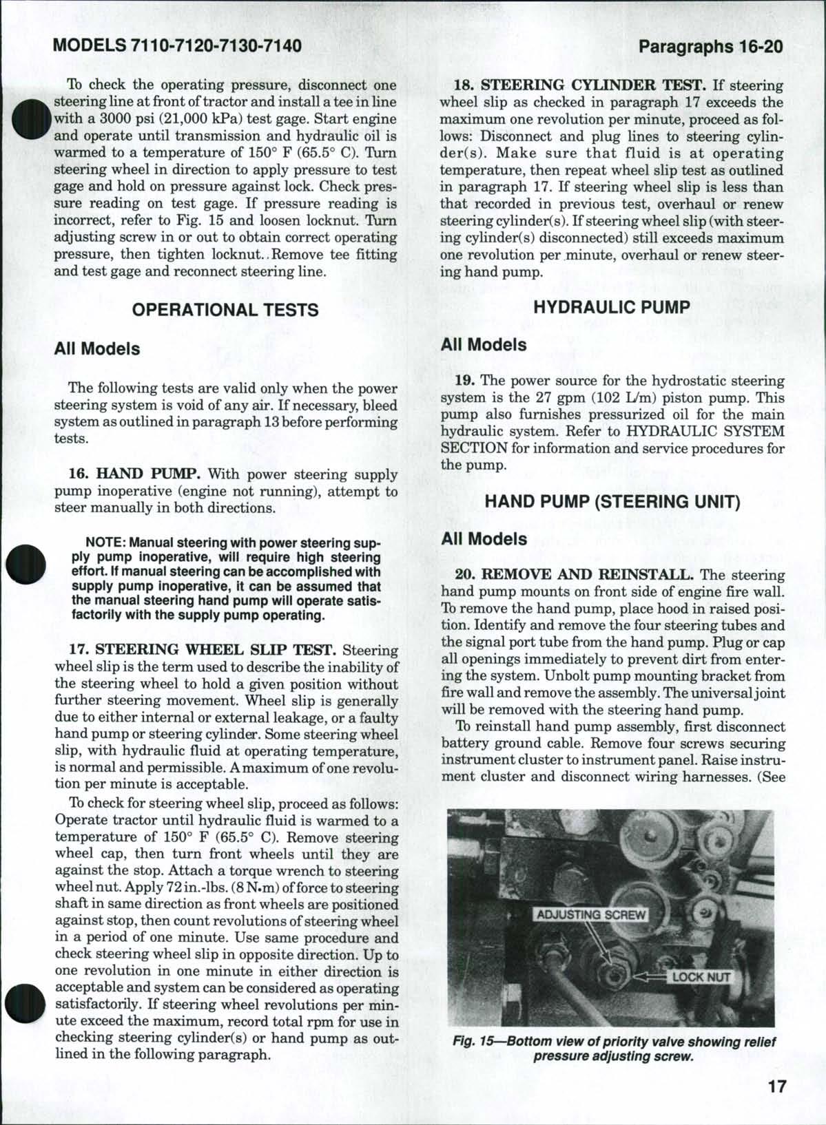
Tb check the operating pressure, disconnect one steering line at front oftractor and install a tee in line with a 3000 psi (21,000 kPa) test gage. Start engine and operate until transmission and hydraulic oil is warmed to a temperature of 150° F (65.5° C). Turn steering wheel in direction to apply pressure to test gage and hold on pressure against lock. Check pressure reading on test gage. If pressure reading is incorrect, refer to Fig. 15 and loosen locknut. Turn adjusting screw in or out to obtain correct operating pressure, then tighten locknut.,Remove tee fitting and test gage and reconnect steering line.
OPERATiONAL TESTS
Aii Modeis
The following tests are valid only when the power steering system is void of any air. If necessary, bleed system asoutlined in paragraph 13before performing tests
16. HAND PUMP. With power steering supply pump inoperative (engine not running), attempt to stoer manually in both directions.
NOTE: Manual steering with power steering suppiy pump inoperative, wiii require high steering effort If manual steering can be accomplished with supply pump inoperative, it can be assumed that the manual steering hand pump will operate satisfactoriiy with the supply pump operating
17. STEERING WHEEL SLIP TEST. Steering wheel slip is the term used to describe the inability of the steering wheel to hold a given position without further steering movement Wheel slip is generally due to either internal or external leakage, or a faulty hand pump or steering cylinder. Some steering wheel slip, with hydraulic fluid at operating temperature, is normal and permissible Amaximum ofone revolution per minute is acceptable
Tb check for steering wheel slip, proceed as follows: Operate tractor until hydraulic fiuid is warmed to a temperature of 150° F (65.5° C). Remove steering wheel cap, then turn front wheels until they are against the stop Attach a torque wrench to steering wheel nut Apply 72in.-lbs (8N.m)offorce to steering shaft in same direction as front wheels are positioned against stop,then count revolutions ofsteering wheel in a period of one minute. Use same procedure and check stoering wheel slip in opposite direction. Up to one revolution in one minute in either direction is acceptable and system can be considered as operating satisfactorily If steering wheel revolutions per minute exceed the maximum, record total rpm for use in checking steering cylinder(s) or hand pump as outhned in the following paragraph.
18. STEERING CYLINDER TEST. If steering wheel slip as checked in paragraph 17 exceeds the maximum one revolution per minute, proceed as follows: Disconnect and plug lines to steering cylinder(s) Make sure that fluid is at operating temperature, then repeat wheel slip test as outlined in paragraph 17 If steering wheel slip is less than that recorded in previous test, overhaul or renew steering cylinders) If steering wheel slip (with steering cylinder(s) disconnected) still exceeds maximum one revolution per minute, overhaul or renew steering hgind pump
HYDRAULIC PUMP
Aii Modeis
19. The power source for the hydrostatic steering system is the 27 gpm (102 L/m) piston pimip. This pump also furnishes pressurized oil for the main hydraulic system. Refer to HYDRAULIC SYSTEM SECTION for information and service procedures for the pump
HAND PUMP (STEERiNG UNIT)
Aii Modeis
20. REMOVE AND REINSTALL. The steering hand pump mounts on front side of engine fire wall. Tb remove the hand pump, place hood in raised position. Identify and remove the four steering tubes and the signal port tube from the hand pump. Plug or cap all openings immediately to prevent dirt from entering the system. Unbolt pump mounting bracket from fire wall and remove the assembly.The universaljoint will be removed with the steering hand pump.
Tb reinstall hand pump assembly, first disconnect battery ground cable Remove four screws securing instrument cluster to instrument panel Raise instrument cluster and disconnect wiring harnesses (See
Fig. 15—Bottom view of priority vaive showing reiief pressure adjusting screw.
Fig. 16.) Lay cluster unit aside. This will provide access to the steering shaft. Have helper ahgn steering shaft in "U"joint as steering hand pump assembly is installed in fire wall. Tighten bracket to fire wall cap screws to a torque of 20-24 ft.-lbs. (27-32 N.m). Reconnect steering lines and signal port line. Reinstall instrument cluster and connect battery ground cable.Start engine and bleed air from steering system as outlined in paragraph 13.
21. OVERHAUL (ROSS UNIT).
Tb disassemble the removed hand pump, drive out roll pin and remove "U" joint and collar (32—Fig. 17) from input shaft (31). Remove dust shield (33), then unbolt and remove pump mountingbracket. Identify and remove hydraulic fittings, inlet (3) and outlet (1) check valves and signal check valve (14).Mark check valves for aid in reassembly. Remove guide pin (7)with "O" ring (6) and check ball (5). Remove cap screws (37) and washers (38) and lift off cover (39). Remove seal ring (40), snap ring (34), back-up ring (35) and seal (36) from cover. Remove thrust washer (41) and thrust bearing (42) from input shaft (31). With input shaft in horizontal position, carefully withdraw input shaft assembly with commutator (20). Remove washer (22) from pump body (16), drive plate (18) from spool (17) and seal assembly (19) from sleeve in body (16). Hold adjusting screw (12) from turning and remove locknut (8). Push adjusting screw (12), torsion blades (13)and spool (17)fi'ombody.Remove adjusting screw and torsion blades from spool. Remove plug (9) and "O" ring (10). Remove commutator (20) and seal assembly (21).Clamp not more than oneinch (25.4mm) of input shaft (31) in protected jaws of vise and remove seven cap screws (23). Remove manifold (24), drive link (26 or 26A) with pins (25), stator-rotor set (27 or 27A) and spacer (28 or 28A).
NOTE: The rotor used in two-wheei drive hand pumps is equipped with vanes (29) and vane springs (30) that can fali out. Do not lose these parts. The rotor set used on models with front drive axie
is not equipped with vanes or springs and is a thicker set
The spacer (28) used with two-wheel drive imits is located in the center of rotor Spacer (28A) used with front drive axle hand pump is located in the recess in input shaft (31)
Remove adjusting screw (12) and torsion blades (13) from spool (17). Clean and inspect all parts for
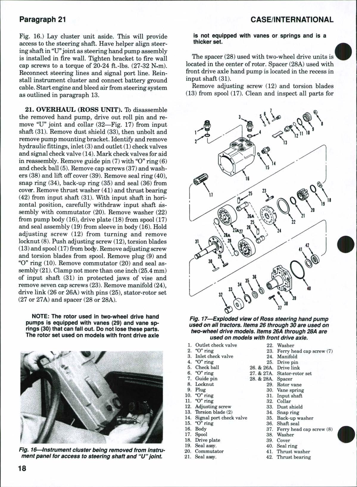
Fig. 17—Expioded view of Ross steering hand pump used on aii tractors, items 26 through 30 are used on two-wheei drive modeis. items 26A through 28A are used on modeis with front drive axie.
Fig. 16—Instrument cluster being removed from instrument panei for access to steering shaft and "U"joint.
excessive wear or other damage. If spool(17)or sleeve in body (16) are worn, renew hand pump assembly. Commutator (20)and manifold (24)are available only as a matched set, as are the stator and rotor Refer to Fig 18when checking the stator-rotor set and to Fig 19when checking vane springs
When reassembling, use all new seal rings, "O** rings and oil seals and lubricate seals with white petroleum jelly.
Install "O"ring (10—Fig. 17) and pump plug (9) in body and tighten plug to a torque of 55-75 ft.-lhs. (75-102 N.m). Install new "O'' ring (11) on adjusting screw (12) and place the two torsion blades in slot in adjusting screw Each torsion hlade has an identification dot Torsion blades must be installed with dots facing the outside, so dots are at opposite ends of the spool. Insert torsion blades and adjusting screw into flat end of valve spool (17) so blades are installed in the narrowest slot in valve spool. Lubricate exterior of valve spool with new Hy-Tran Plus oil and install valve spool Tighten nut (8) on adjusting screw finger tight Use drive plate (18) and commutator (20) as assembly guides to position valve spool. Center the commutator lugs in the slots ofbody.Remove commutator and drive plate. Tighten locknut (8) to a torque of 10-15 fl.-lbs (14-20 N.m) Install new seal assembly (21) in groove of open end of commutator and install commutator into manifold (24) Place commutator and manifold on a clean surface with commutator side down. Install drive link (26or 26A)and drive pins (25) into the commutator. Install the rotor over the drive pin and install the stator. On two-wheel
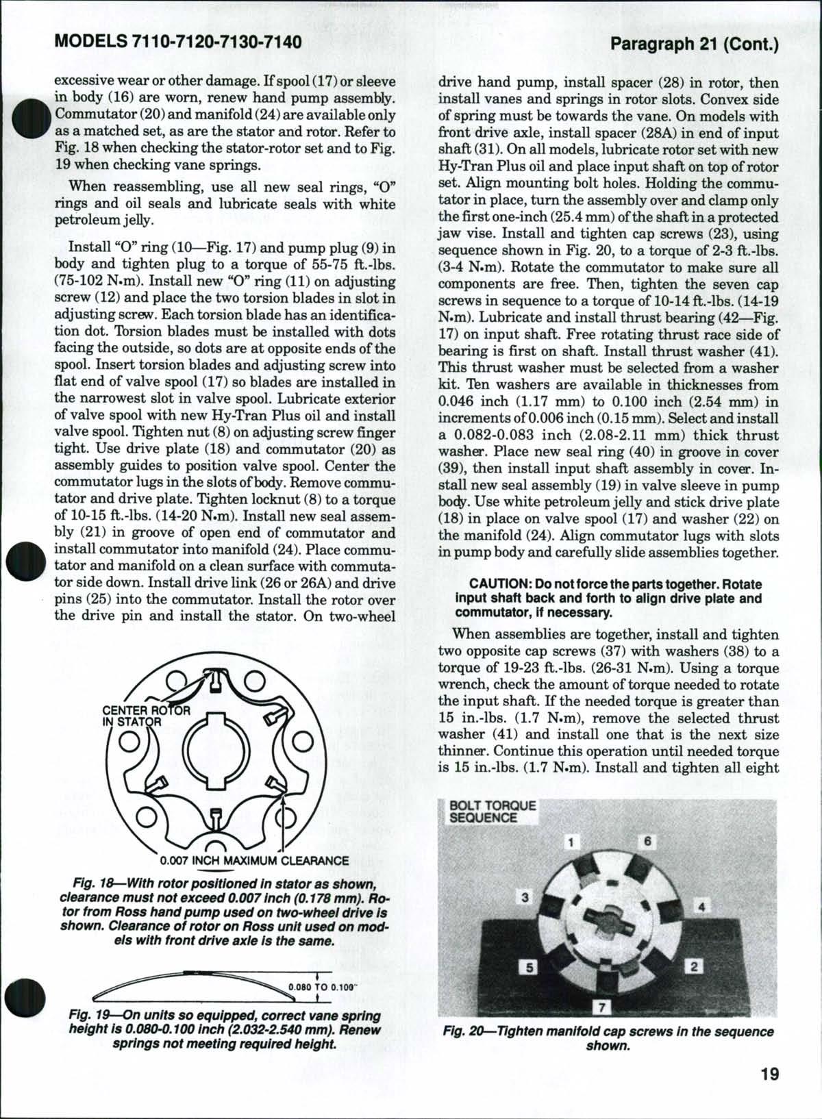
Fig. 18—With rotor positioned in stator as shown, clearance must not exceed 0.007 inch (0.178 mm). Rotor from Ross hand pump used on two-wheel drive is shown. Clearance of rotor on Ross unit used on models with front drive axie is the same.
drive hand pump, install spacer (28) in rotor, then install vanes and springs in rotor slots Convex side of spring must he towards the vane On models with front drive axle, install spacer (28A) in end of input shaft (31) On all models,lubricate rotor set with new Hy-Tran Plus oil and place input shaft on top of rotor set Align mounting bolt holes Holding the commutator in place, turn the assembly over and clamp only the first one-inch (25.4mm) ofthe shaft in a protected jaw vise Install and tighten cap screws (23), using sequence shown in Fig 20, to a torque of 2-3 fl.-lbs (3-4 N.m) Rotate the commutator to make sure all components are free Then, tighten the seven cap screws in sequence to a torque of 10-14 ft.-lbs. (14-19 N»m) Lubricate and install thrust bearing (42—Fig 17) on input shaft Free rotating thrust race side of bearing is first on shaft Install thrust washer (41) This thrust washer must be selected from a washer kit Ten washers are available in thicknesses from 0.046 inch (1.17 mm) to 0.100 inch (2.54 mm) in increments of0.006 inch (0.15mm) Select and install a 0.082-0.083 inch (2.08-2.11 mm) thick thrust washer Place new seal ring (40) in groove in cover (39), then install input shaft assembly in cover Install new seal assembly (19) in valve sleeve in pump hody Use white petroleum jelly and stick drive plate (18) in place on valve spool (17) and washer (22) on the manifold (24) Align commutator lugs with slots in pump body and carefully slide assemblies together
CAUTION: Donotforcethe partstogether Rotate input shaft back and forth to align drive piate and commutator, if necessary
When assemblies are together, install and tighten two opposite cap screws (37) with washers (38) to a torque of 19-23 ft.-lbs. (26-31 N.m) Using a torque wrench, check the amount of torque needed to rotate the input shaft If the needed torque is greater than 15 in.-lhs. (1.7 N.m), remove the selected thrust washer (41) and install one that is the next size thinner. Continue this operation until needed torque is 15 in.-lbs (1.7 N.m) Install and tighten all eight
BOLT TORQUE SEOUENCE
Fig. I^'-On units so equipped, correct vane spring height Is 0.080-0.100 Inch (2.032-2.540 mm). Renew springs not meeting required height.
Fig. 20—Tighten manifold cap screws In the sequence shown.
CLICK HERE TO DOWNLOAD THE COMPLETE MANUAL
• Thank you very much for reading the preview of the manual.
• You can download the complete manual from: www.heydownloads.com by clicking the link below
• Please note: If there is no response to CLICKING the link, please download this PDF first and then click on it.
CLICK HERE TO DOWNLOAD THE
cap screws (37) evenly to a torque of 19-23 ft.-lbs. (26-31 N.m) Install shaft seal (36)with seal lip facing inward Install back-up ring (35) and snap ring (34) with rounded edge inward Fill cavity in pump cover bore with white petroleum jelly and install dust shield (33) Install check ball (5) and guide pin (7) with new"O" ring (6) Tighten guide pin (7)toa torque of 10-14 ft.-lbs. (14-19 N.m) Inspect check valves(1, 3 and 14) and make sure they are clean and operate freely. Use new "O" rings and install signal port check valve (14), outlet check valve (1), inlet check valve (3) and the other two (right and left turn) hydraulic fittings Tighten signal port check valve to a torque of 15-25 ft.-lbs. (20-34 N.m), and the inlet and outlet check valves, and the other two fittings, to a torque of 22-27 ft.-lhs. (30-37 N.m) Install "U" joint and collar (32) and secure with the roll pin
Reinstall hand pximp assemhly as outlined in paragraph 20. Start engine and operate at 1500 rpm. Rotate steering wheel from lock to lock several times to hleed all air from system.
The procedure for balancing the steering hand pump is as follows: With engine operating at 1500 rpm, place front wheels in straight-ahead position Using a torque wrench on steering wheel nut, turn

steering wheel one turn to the left and record amount of torque needed Center front wheels and check amount of torque needed to turn steering wheel turn to the right. Record this reading If the readings are not within 2-3 in.-lbs (0.22-0.33 N.m), balance the unit as follows: Loosen locknut (8—Fig 17) and turn adjusting screw (12) counterclockwise a slight amount if torque reading was greater for the right turn TVtm adjusting screw clockwise if torque reading wasgreater for left turn Adjusting screw will require a turn of 10 degrees or less to correct the balance Tighten locknut and recheck the torque in both directions Balance is correct when torque readings in both directions are within 2-3 in.-lbs (0.220.33 N.m) When balance is correct, tighten locknut to a torque of 20-25 ft.-lbs. (27-34 N.m)
STEERING CYLINDER(S)
All Two-Wheel Drive Models
22, R&RAND OVERHAUL.Tb remove the power steering cylinder (5—Fig. 21), disconnect both steering lines. Cap or plug all openings. Loosen ball joint clamp bolt (6). Usinga wrench onthe flat end ofpiston rod, turn piston rod out of ball joint (7). Remove cylinder mounting bolts (1) and washers (2), then withdraw cylinder from center steering arm (3). Remove trunnions (4) from cylinder.
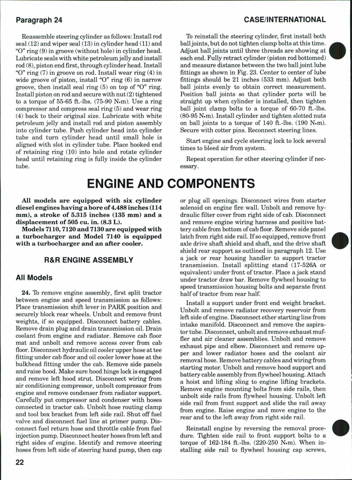
To disassemble the steering cylinder, use a spanner wrench and rotate cylinder head (3—Fig. 22) until sharp end of retaining ring (4) is visible in slot in cylinder tube (7). Raise end of retaining ring out of slot and rotate cylinder head to remove the retaining ring. Remove cylinder head assembly from cylinder tube. Remove cylinder head from opposite end of cylinder tube in the same manner. Remove "O" ring (6), back-up ring (5), wiper seal (1) and rod seal (2) from cylinder heads. Withdraw piston rod (10), then remove piston seal (9) and "O" ring (8).
Inspect cylinder tube (7) for scoring, grooves or out-of^roundness. Light scoring can be polished out by using a fine emery cloth and oil, using a rotary motion while polishing. Heavy scoring, grooving or out-of-roundness will require renewal of cylinder tube. Check rod end piston (10) for scoring, grooving and straightness and renew as necessary.
Renew all "O" rings, seals and back-up rings (available in a kit) during reassembly.
Reassemble steering cylinder as follows: Install "0" ring (8)in piston, then install piston seal (9)on top of "O" ring. Use a ring compressor and compress piston seal back to its original size. Lubricate with white petroleum jelly and install piston rod assembly into cylinder tube. Install rod seal (2) and wiper seal (1) in cylinder heads and back-up ring (5) and "O" ring (6) in wide groove of cylinder heads. "O" rings must be toward inside of cylinder. Lubricate and install
Fig. 21—View of power steering cylinder removed from two-wheel drive tractor with standard adjustable front axle,
over piston rod and into cylinder tube Turn cylinder heads until the small hole appears in slot of cylinder tube Install hooked end ofretaining ring (4)into hole and rotate cylinder head until retaining ring is fully inside the cylinder tube
Th reinstall steering cylinder, reverse the removal procedure. Tighten mounting cap screws (1—Fig. 21) to a torque of460-510 ft.-lbs. (620-690 N.m). Tighten piston rod into balljoint to a torque of 110-125 ft.-lbs. (150-170 N.m) and tighten clamp bolt (6) to a torque of25-30 ft.-lbs. (35-40N.m). Reconnect steering lines. Start engine and cycle steering lock to lock several times to bleed air from system
All Models With Front Drive Axle
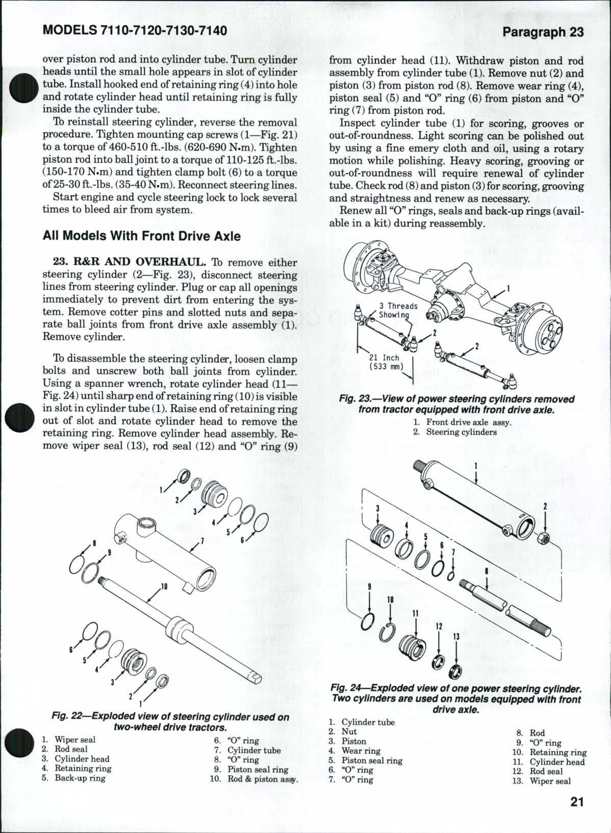
23. R&R AND OVERHAUL. Ib remove either steering cylinder (2—Fig. 23), disconnect steering lines from steering cylinder. Plug or cap all openings immediately to prevent dirt from entering the system Remove cotter pins and slotted nuts and separate ball joints from front drive axle assembly (1) Remove cylinder
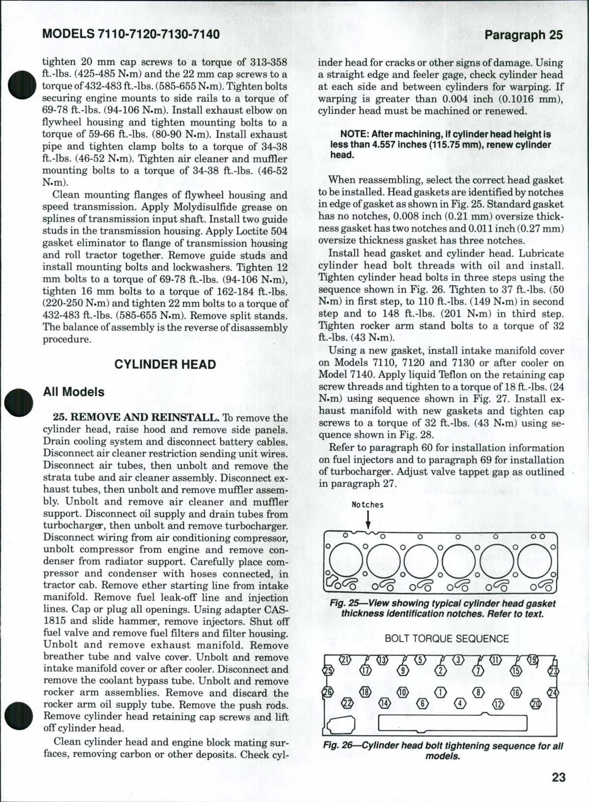
Todisassemble the steering cylinder, loosen clamp bolts and unscrew both ball joints from cylinder. Using a spanner wrench, rotate cylinder head (11 Fig.24)until sharp end ofretaining ring (10)is visible in slotin cylinder tube (1) Raise end ofretaining ring out of slot and rotate cylinder head to remove the retaining ring. Remove cylinder head assembly Remove wiper seal (13), rod seal (12) and "O" ring (9)
22—Exploded
Wiper seal
Rod seal
Cylinder head
Retaining ring
Back-up ring
6 "O"ring 7 Cylinder tube
8 Wring 9 Piston seal ring 10 Rod &piston
from cylinder head (11). Withdraw piston and rod assembly from cylinder tube (1). Remove nut (2) and piston (3) from piston rod (8). Remove wear ring (4), piston seal (5) and "O" ring (6) from piston and "O" ring (7) from piston rod.
Inspect cylinder tube (1) for scoring, grooves or out-of-roundness Light scoring can be polished out by using a fine emery cloth and oil, using a rotary motion while polishing Heavy scoring, grooving or out-of-roundness will require renewal of cylinder tube Check rod (8)and piston (3)for scoring, grooving and straightness and renew as necessary
Renew all "O" rings, seals and back-up rings (available in a kit) during reassembly
1 Front drive axle assy
2 Steering cylinders
24—Exploded view of one power steering cylinder. Two cylinders are used on models equipped with front drive axle.
1 Cylinder tube 2 Nut 8 Rod 3 Piston 9 «O"ring 4. Wear ring 10. Retaining ring 5 Piston seal ring H Cylinder head 6 "O"ring 12 Rod seal 7 «O"ring 13 Wiper seal
Fig.
view of steering cylinder used on two-wheel drive tractors.
Fig. 23.—View of power steering cylinders removed from tractor equipped with front drive axle.
Fig.
Reassemble steering cylinder as follows: Install rod seal (12) and wiper seal (13)in cylinder head (11) and "O" ring (9)in groove (without hole) in cylinder head Lubricate sealswith white petroleumjelly and install rod (8), piston end first, through cylinder head Install "O" ring (7) in groove on rod Install wear ring (4) in wide groove of piston, install "O" ring (6) in narrow groove, then install seal ring (5) on top of "O" ring. Install piston on rod and securewith nut (2) tightened to a torque of 55-65 ft.-lbs. (75-90 N.m) Use a ring compressor and compress seal ring (5) and wear ring (4) back to their original size Lubricate with white petroleum jelly and install rod and piston assembly into cylinder tube Push cylinder head into cylinder tube and turn cylinder head until small hole is aligned with slot in cylinder tube Place hooked end of retaining ring (10) into hole and rotate cylinder head until retaining ring is fully inside the cylinder tube
Tb reinstall the steering cylinder, first install both balljoints,but donot tighten clamp bolts at this time Adjust ball joints until three threads are showing at each end Fully retract cyHnder (piston rod bottomed) and measure distance between the twoballjoint lube fittings as shown in Fig 23 Center to center of lube fittings should be 21 inches (533 mm) Adjust both ball joints evenly to obtain correct measurement Position ball joints so that cylinder ports will be straight up when cylinder is installed, then tighten ball joint clamp bolts to a torque of 60-70 ft.-lbs. (80-95 N.m) Install cylinder and tighten slotted nuts on ball joints to a torque of 140 ft.-lbs. (190 N.m) Secure with cotter pins Reconnect steering lines
Start engine and cycle steering lock to lock several times to bleed air from system.
Repeat operation for other steering cylinder if necessary
ENGINE AND COMPONENTS
All models are equipped with six cylinder diesel engineshaving abore of4.488inches (114 mm), a stroke of 5.315 inches (135 mm) and a displacement of 505 cu. in. (8.3 L).
Models 7110,7120and7130are equipped with a turbocharger and Model 7140 is equipped with a turbocharger and an after cooler*
R&R ENGINE ASSEMBLY
All Models
24. To remove engine assembly, first split tractor between engine and speed transmission as follows: Place transmission shift lever in PARK position and securely block rear wheels. Unbolt and remove front weights, if so equipped. Disconnect battery cables. Remove drain plug and drain transmission oil. Drain coolant from engine and radiator Remove cab floor mat and unbolt and remove access cover from cab floor Disconnect hydraulic oilcooler upper hoseat tee fitting under cab fioor and oil cooler lower hose at the bulkhead fitting under the cab. Remove side panels and raise hood. Make sure hood hinge lock is engaged and remove left hood strut. Disconnect wiring from air conditioning compressor, unbolt compressor from engine and remove condenser from radiator support Carefully put compressor and condenser with hoses connected in tractor cab. Unbolt hose routing clamp and tool box bracket from left side rail. Shut off fuel valve and disconnect fuel line at primer pump. Disconnect fuel return hose and throttle cable from fuel injection pump Disconnect heater hosesfromleft and right sides of engine Identify and remove steering hoses from left side of steering hand pump, then cap
or plug all openings. Disconnect wires from starter solenoid on engine fire wall. Unbolt and remove hydraulic filter cover from right side of cab. Disconnect and remove engine wiring harness and positive battery cable from bottom ofcabfioar.Remove side panel latch from right side rail If soequipped, remove front axle drive shaft shield and shaft, and the drive shaft shield rear support as outlined in paragraph 12. Use a jack or rear housing handler to support tractor transmission. Install splitting stand (17-526A or equivalent) under front of tractor Place ajack stand under tractor draw bar Remove fiywheel housing to speed transmission housing bolts and separate front half of tractor from rear half.
Install a support under front end weight bracket. Unbolt and remove radiator recovery reservoir from left side ofengine Disconnect ether starting linefrom intake manifold Disconnect and remove the aspirator tube Disconnect, imbolt and remove exhaust muffler and air cleaner assemblies Unbolt and remove exhaust pipe and elbow. Disconnect and remove upper and lower radiator hoses and the coolant air removal hose. Remove battery cables and wiring from starting motor Unbolt and remove hood support and battery cable assembly from fiywheel housing Attach a hoist and lifting sling to engine lifting brackets Remove engine mounting bolts from side rails, then unbolt side rails from fiywheel housing. Unbolt left side rail from front support and slide the rail away from engine Raise engine and move engine to the rear and to the left away from right side rail
Reinstall engine by reversing the removal procedure Tighten side rail to front support bolts to a torque of 162-184 ft.-lbs. (220-250 N.m). When installing side rail to fiywheel housing cap screws,
tighten 20 mm cap screws to a torque of 313-358 ft.-lbs. (425-485 N.m) and the 22 mm cap screws to a torque of432-483 ft.-lbs. (585-655N.m) Tighten bolts securing engine mounts to side rails to a torque of 69-78 ft.-lbs. (94-106 N.m) Install exhaust elbow on fiywheel housing and tighten mounting bolts to a torque of 59-66 ft.-lbs. (80-90 N.m) Install exhaust pipe and tighten clamp bolts to a torque of 34-38 ft.-lbs. (46-52 N.m) Tighten air cleaner and muffler mounting bolts to a torque of 34-38 ft.-lbs. (46-52 N.m)
Clean mounting flanges of fljrwheel housing and speed transmission Apply Molydisulfide grease on splines oftransmission input shaft Install two guide studs in the transmission housing Apply Loctite 504 gasket eliminator to flange of transmission housing and roll tractor togethe* Remove guide studs and install mounting bolts and lockwashers Tighten 12 mm bolts to a torque of 69-78 ft.-lbs. (94-106 N.m), tighten 16 mm bolts to a torque of 162-184 ft.-lbs. (220-250 N.m) and tighten 22 mm bolts to a torque of 432-483 ft.-lbs. (585-655 N.m) Remove split stands The balance ofassembly isthe reverse of disassembly procedure.
CYLINDER HEAD
All Models
25. REMOVE AND REINSTALL. Ib remove the cylinder head, raise hood and remove side panels. Drain cooling system and disconnect battery cables. Disconnect air cleaner restriction sending unit wires. Disconnect air tubes, then unbolt and remove the strata tube and air cleaner assembly Disconnect exhaust tubes, then unbolt and remove muffler assembly Unbolt and remove air cleaner and muffler support Disconnect oil supply and drain tubes from turbocharger, then unbolt and remove turbocharger. Disconnect wiring from air conditioning compressor, unbolt compressor from engine and remove condenser from radiator support. Carefully place compressor and condenser with hoses connected, in tractor cab Remove ether starting line from intake manifold Remove fuel leak-off line and injection lines. Cap or plug all openings. Using adapter CAS1815 and slide hammer, remove injectors. Shut off fuel valve and remove fuel filters and filter housing. Unbolt and remove exhaust manifold. Remove breather tube and valve cover Unbolt and remove intake manifold cover or after cooler Disconnect and remove the coolant bypass tube Unbolt and remove rocker arm assemblies Remove and discard the rocker arm oil supply tube. Remove the push rods. Remove cylinder head retaining cap screws and lift off cylinder head.
Clean cylinder head and engine block mating surfaces, removing carbon or other deposits Check cyl-
inder head for cracks or other signs ofdamage. Using a straight edge and feeler gage, check cylinder head at each side and between cylinders for warping. If warping is greater than 0.004 inch (0.1016 mm), cylinder head must be machined or renewed.
NOTE: After machining, if cyiinder liead height is less than 4.557 inches (115.75 mm), renew cylinder head.
When reassembling, select the correct head gasket tobeinstalled Head gaskets are identified by notches in edge ofgasket as shown in Fig 25 Standard gasket has no notches, 0.008 inch (0.21 mm) oversize thickness gasket has two notches and 0.011 inch (0.27 mm) oversize thickness gasket has three notches. Install head gasket and cylinder head Lubricate cylinder head bolt threads with oil and install. Tighten cylinder head bolts in three steps using the sequence shown in Fig. 26. Tighten to 37 ft.-lbs. (50 N.m) in first step, to 110 ft.-lbs. (149 N.m) in second step and to 148 ft.-lbs. (201 N.m) in third step Tighten rocker arm stand bolts to a torque of 32 ft.-lbs. (43 N.m)
Using a new gasket, install intake manifold cover on Models 7110, 7120 and 7130 or after cooler on Model 7140 Apply liquid Ifeflon on the retaining cap screw threads and tighten to a torque of 18 ft.-lbs. (24 N.m) using sequence shown in Fig. 27. Install exhaust manifold with new gaskets and tighten cap screws to a torque of 32 ft.-lbs. (43 N.m) using sequence shown in Fig. 28.
Refer to paragraph 60 for installation information on fuel injectors and to paragraph 69 for installation of turbocharger Adjust valve tappet gap as outlined in paragraph 27
Notches
o \9/^—N O o ) o o "1
Fig. 25—View showing typicai cyiinder head gasket thickness identification notches. Refer to text.
Fig. 26 Cylinder head bolt tightening sequence for all models.
BOLT TORQUE SEQUENCE
Paragraphs 26-27
Complete the assembly by reversing the disassembly procedure. Other tightening torques are as follows:
Valve cover bolts
Filter housing nut
Fuel injector bolts
Turbocharger mounting nuts
VALVES AND SEATS
All Models
CASE/INTERNATIONAL
Intake
Face and seat angle
Stem diameter
18 ft.-lbs. (24 N.m)
24 ft.-lbs. (32 N.m)
18 ft.-lbs. (24 N.m)
24 ft.-lbs. (32 N.m)
Stem to guide clearance
Seat width
Valve tappet gap (cold)
Valve recession from face of cylinder head
Exhaust
Face and seat angle
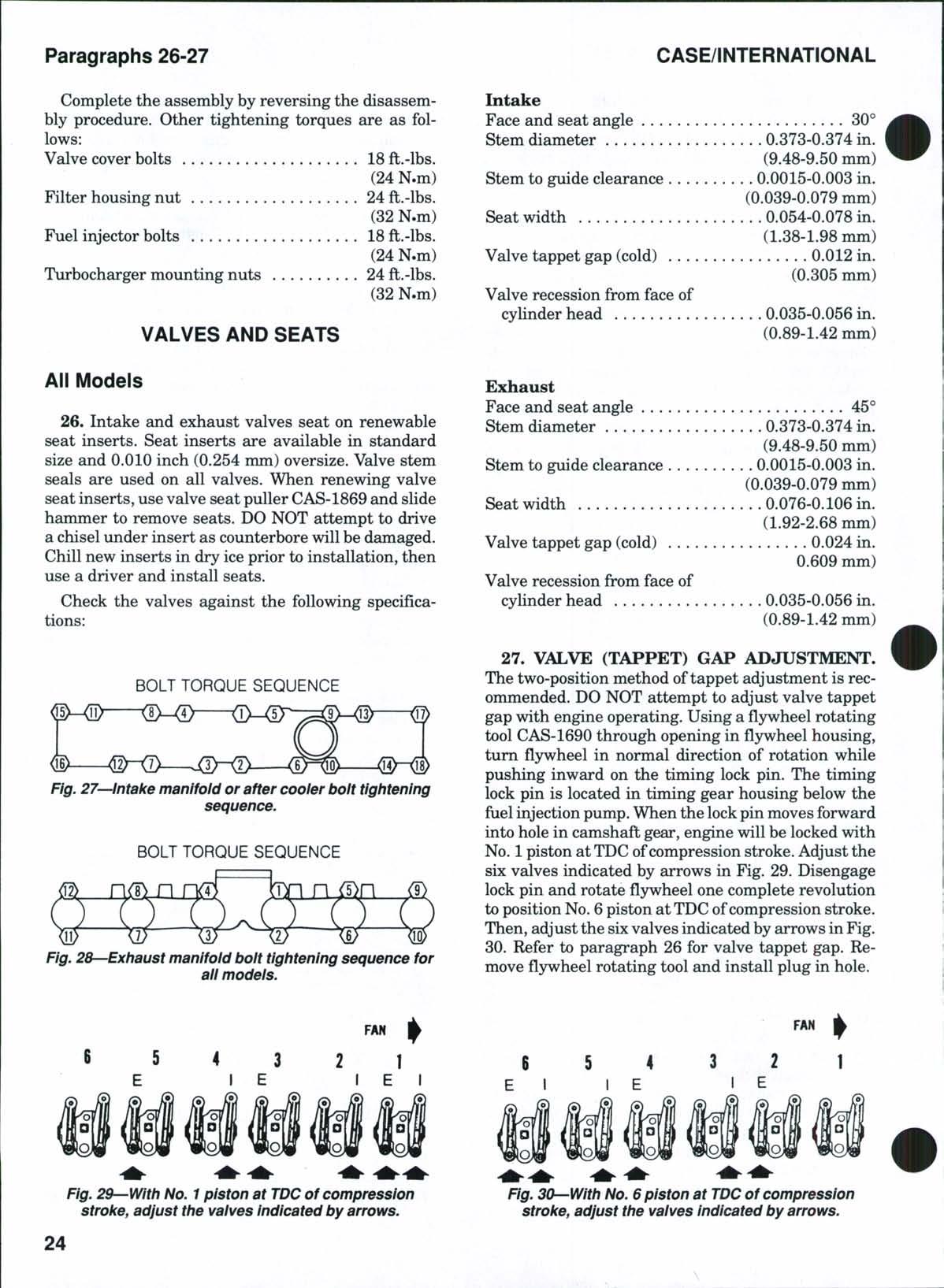
26. Intake and exhaust valves seat on renewable seat inserts Seat inserts are available in standard size and 0.010 inch (0.254 mm) oversize Valve stem seals are used on all valves When renewing valve seat inserts, use valve seat puller CAS-1869 and slide hammer to remove seats. DO NOT attempt to drive a chisel under insert as counterbore will be damaged. Chill new inserts in dry ice prior to installation, then use a driver and install seats
Check the valves against the following specifications:
BQLT TORQUE SEQUENCE
Fig. 27—Intake manifold or after cooler bolt tightening sequence.
Stem diameter
Stem to guide clearance
Seat width
Fig. 28—Exhaust manifold bolt tightening sequence for all models.
30°
0.373-0.374 in (9.48-9.50 mm)
0.0015-0.003 in (0.039-0.079 mm)
0.054-0.078 in. (1.38-1.98 mm)
0.012 in. (0.305 mm)
0.035-0.056 in. (0.89-1.42 mm)
45""
0.373-0.374 in (9.48-9.50 mm)
0.0015-0.003 in (0.039-0.079 mm)
0.076-0.106 in (1.92-2.68 mm)
Valve tappet gap (cold) 0.024 in 0.609 mm)
Valve recession from face of cylinder head
0.035-0.056 in (0.89-1.42 mm)
27. VALVE (TAPPET) GAP ADJUSTMENT.
The two-position method oftappet adjustment is recommended. DO NOT attempt to adjust valve tappet gap with engine operating Using a fljrwheel rotating tool CAS-1690 through opening in flywheel housing, turn flywheel in normal direction of rotation while pushing inward on the timing lock pin The timing lock pin is located in timing gear housing below the fuel injection pump. When the lockpin moves forward into hole in camshaft gear, engine will be locked with No 1 piston at TDCofcompression stroke Adjust the six valves indicated by arrows in Fig 29 Disengage lock pin and rotatefl3rwheelone complete revolution to position No. 6piston at TDCofcompression stroke. Then, adjust the sixvalves indicated by arrows in Fig. 30. Refer to paragraph 26 for valve tappet gap. Remove flywheel rotating tool and install plug in hole
FAH FAN
Fig. 29—With No. 1 piston at TDC of compression stroke, adjust the vaives indicated by arrows.
Fig. 30—With No. 6 piston at TDC of compression stroke, adjust the vaives indicated by arrows.
VALVE GUIDES AND SPRINGS
All Models
28. The intake and exhaust valve guides are interchangeable Ifvalve guides are worn beyond the limit of0.376inch (9.559mm),renew guides asfollows: Use tool CAS-10823 or equivalent and press on bottom of guides until removed. Then, use tool CAS-10823 and press on top end of guides until top of intake guides are 0.813-0.833 inch (20.65-21.16 mm) above spring recess in head or top of exhaust guides are 0.8860.906 inch (22.50-23.01 mm) above spring recess in head Ream installed guides to inside diameter of 0.3755 inch (9.539 nun) Stem seals are used on all valves
Intake and exhaust valve springs are interchangeable Renew any spring that is cracked, discolored or does not meet the following specifications:
Free length
Test length
2.585 in (65.66 mm)
2.0 in. (50.8 mm)
Test load 104-115 lbs. (464.5-513.5 N)
ROCKER ARMS
All Models
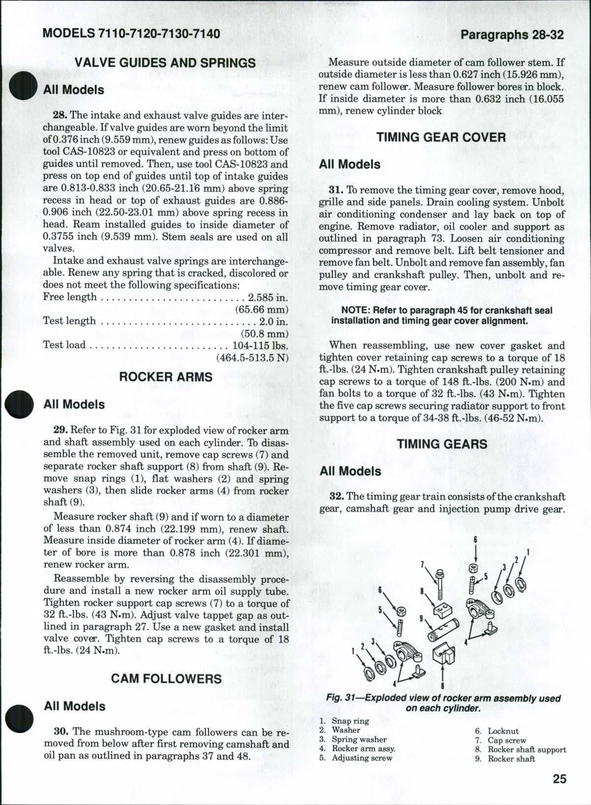
29. Refer to Fig. 31for exploded view ofrocker arm and shaft assembly used on each cylinder. To disassemble the removed unit, remove cap screws (7) and separate rocker shaft support (8) from shaft (9). Remove snap rings (1), flat washers (2) and spring washers (3), then slide rocker arms (4) from rocker shaft (9)
Measure rocker shaft (9) and if worn to a diameter of less than 0.874 inch (22.199 mm), renew shaft Measure inside diameter of rocker arm (4) If diameter of bore is more than 0.878 inch (22.301 mm), renew rocker arm.
Reassemble by reversing the disassembly procedure and install a new rocker arm oil supply tube Tighten rocker support cap screws (7) to a torque of 32 ft.-lbs. (43 N.m). Adjust valve tappet gap as outlined in paragraph 27. Use a new gasket and install valve cover Tighten cap screws to a torque of 18 ft.-lbs. (24 N.m)
CAM FOLLOWERS
All Models
30 The mushroom-type cam followers can be removed from below after first removing camshaft and oil pan as outlined in paragraphs 37 and 48.
Measure outside diameter of cam follower stem If outside diameter is less than 0.627 inch (15.926 mm), renew cam follower Measure follower bores in block If inside diameter is more than 0.632 inch (16.055 mm), renew cylinder block
TIMING GEAR COVER
All Models
31 Tb remove the timing gear cover, remove hood, grille and side panels Drain cooling system Unbolt air conditioning condenser and lay back on top of engine Remove radiator, oil cooler and support as outlined in paragraph 73 Loosen air conditioning compressor and remove belt Lift belt tensioner and remove fan belt Unbolt and remove fan assembly, fan pulley and crankshaft pulley. Then, unbolt and remove timing gear cove*.
NOTE: Refer to paragraph 45 for crankshaft seal installation and timing gear cover alignment
When reassembling, use new cover gasket and tighten cover retaining cap screws to a torque of 18 ft.-lbs. (24 N.m). Tighten crankshaft pulley retaining cap screws to a torque of 148 ft.-lbs. (200 N.m) and fan bolts to a torque of 32 ft.-lbs. (43 N.m). Tighten the five cap screws securing radiator support to front support to a torque of 34-38 ft.-lbs. (46-52 N.m).
TIMING GEARS
All Models
32 The timing gear train consists ofthe crankshaft gear, camshaft gear and injection pump drive gear
Fig. 31—Expioded view of rocker arm assembly used on each cylinder.
CLICK HERE TO DOWNLOAD THE COMPLETE MANUAL
• Thank you very much for reading the preview of the manual.
• You can download the complete manual from: www.heydownloads.com by clicking the link below
• Please note: If there is no response to CLICKING the link, please download this PDF first and then click on it.
CLICK HERE TO DOWNLOAD THE
Engine oil pump is mounted on front of engine block inside the timing gear housing and drives through an idler gear from crankshaft gear, becoming part of the gear train Refer to the appropriate following paragraphs for timing, inspection and R&R information
33. TIMING MARKS. When installing camshaft gear and crankshaft gear, align single punch mark on
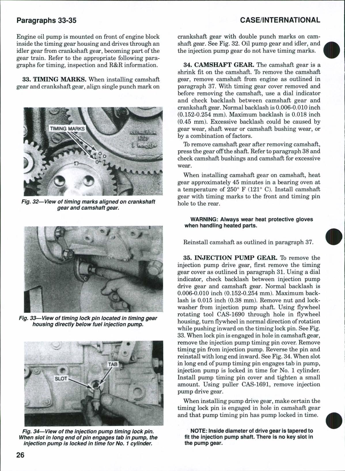
crankshaft gear with double punch marks on camshaft gear. See Fig. 32. Oil pump gear and idler, and the injection pump gear do not have timing marks.
34. CAMSHAFT GEAR. The camshaft gear is a shrink fit on the camshaft To remove the camshaft gear, remove camshaft from engine as outlined in paragraph 37 With timing gear cover removed and before removing the camshaft, use a dial indicator and check backlash between camshaft gear and crankshaft gear Normal backlash is 0.006-0.010 inch (0.152-0.254 mm) Maximum backlash is 0.018 inch (0.45 mm) Excessive backlash could be caused by gear wear, shaft wear or camshaft bushing wear, or by a combination of factors
To remove camshaft gear after removing camshaft, press the gear offthe shaft. Refer toparagraph 38 and check camshaft bushings and camshaft for excessive wear.
When installing camshaft gear on camshaft, heat gear approximately 45 minutes in a bearing oven at a temperature of 250° F (121° C) Install camshaft gear with timing marks to the front and timing pin hole to the rear
WARNING: Always wear heat protective gloves when handling heated parts.
Reinstall camshaft as outlined in paragraph 37.
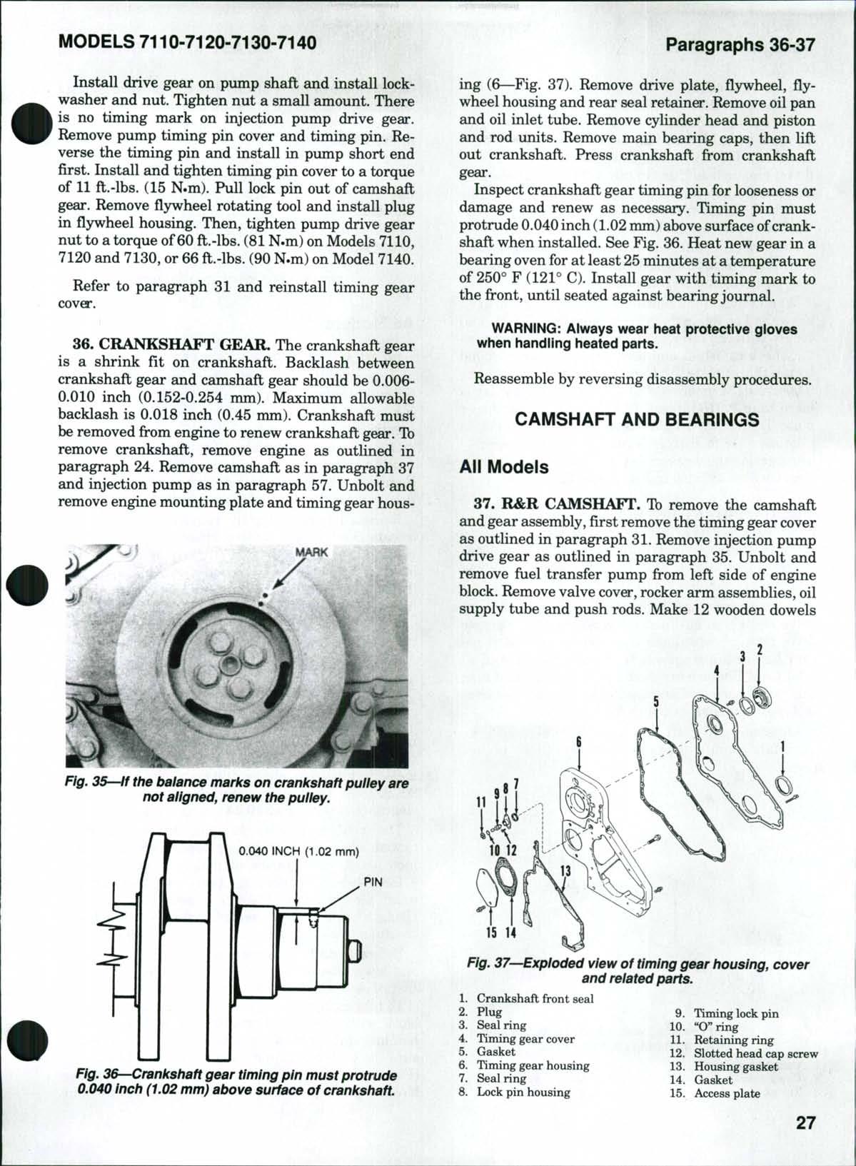
35. INJECTION PUMP GEAR. To remove the injection pump drive gear, first remove the timing gear cover as outlined in paragraph 31 Using a dial indicator, check backlash between injection pump drive gear and camshaft gear. Normal backlash is 0.006-0.010 inch (0.152-0.254 mm). Maximum backlash is 0.015 inch (0.38 mm) Remove nut ^ d lockwasher from injection pump shaft Using flywheel rotating tool CAS-1690 through hole in flywheel housing, turnfljrwheelin normal direction of rotation while pushing inward onthe timing lock pin. See Fig. 33.When lockpin is engaged in hole in camshaft gear, remove the injection pump timing pin cover. Remove timing pin from injection pump Reverse the pin and reinstall with longend inward See Fig 34 When slot in long end ofpump timing pin engages tab in pump, injection pump is locked in time for No. 1 cylinder. Install pump timing pin cover and tighten a small amount. Using puller CAS-1691, remove injection pump drive gear
When installing pump drive gear, make certain the timing lock pin is engaged in hole in camshaft gear and that pump timing pin has pump locked in time.
NOTE: Inside diameter of drive gear is tapered to fit the injection pump shaft. There is no key siot in the pump gear.
Fig. 32—View of timing marks aiigned on crankshaft gear and camshaft gear.
Fig. 33—View of timing io6k pin iocated in timing gear housing directiy below fuel Injection pump.
Fig. 34 View of the injection pump timing lock pin. When slot in long end of pin engages tab in pump, the injection pump is iocked in time for No. 1 cyiinder.
Install drive gear on pump shaft and install lockwasher and nut Tighten nut a small amount There is no timing mark on injection pump drive gear Remove pump timing pin cover and timing pin Reverse the timing pin and install in pump short end first. Install and tighten timing pin cover to a torque of 11 ft.-lbs. (15 N.m) Pull lock pin out of camshaft gear Remove flywheel rotating tool and install plug in flywheel housing Then, tighten pump drive gear nut to a torque of60 ft.-lbs. (81 N.m) on Models 7110, 7120 and 7130, or 66 ft.-lbs. (90 N.m) on Model 7140
Refer to paragraph 31 and reinstall timing gear cover
36. CRANKSHAFT GEAR. The crankshaft gear is a shrink fit on crankshaft Backlash between crankshaft gear and camshaft gear should be 0.0060.010 inch (0.152-0.254 mm). Maximum allowable backlash is 0.018 inch (0.45 mm). Crankshaft must be removed from engine to renew crankshaft gear. Tb remove crankshaft, remove engine as outlined in paragraph 24 Remove camshaft as in paragraph 37 and injection pump as in paragraph 57 Unbolt and remove engine mounting plate and timing gear hous-
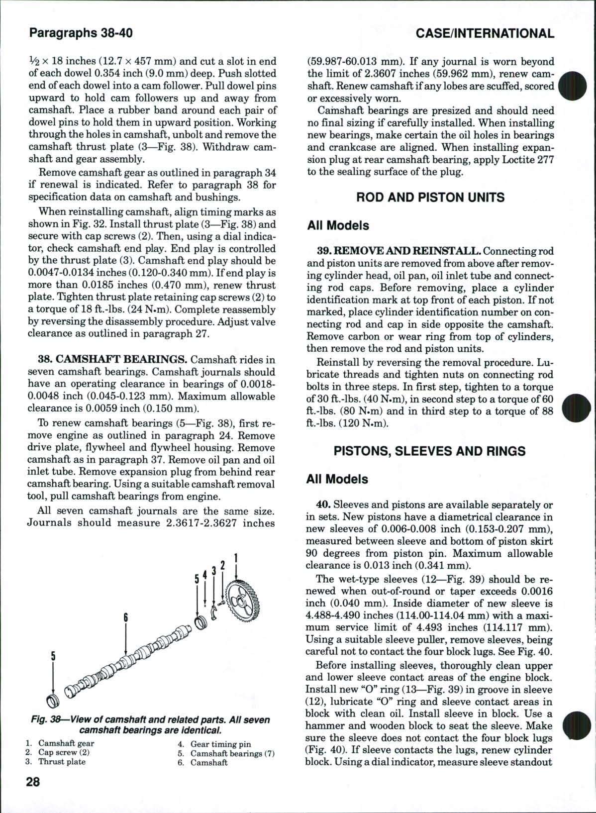
ing (6—Fig. 37). Remove drive plate, flywheel, flywheel housing and rear seal retainer. Remove oil pan and oil inlet tube. Remove cylinder head and piston and rod units. Remove main bearing caps, then lift out crankshaft. Press crankshaft from crankshaft gear.
Inspect crankshaft gear timing pin for looseness or damage and renew as necessary Timing pin must protrude 0.040inch (1.02mm) above surface of crankshaft when installed See Fig 36 Heat new gear in a bearing oven for at least 25minutes at a temperature of 250° F (121° C) Install gear with timing mark to the front, until seated against bearing journal
WARNING: Always wear heat protective gloves when handiing heated parts
Reassemble by reversing disassembly procedures.
CAMSHAFT AND BEARINGS
All Models
37. R&R CAMSHAFT. To remove the camshaft and gear assembly, first remove the timing gear cover as outhned in paragraph 31. Remove injection pump drive gear as outlined in paragraph 35. Unbolt and remove fuel transfer pump from left side of engine block Remove valve cover, rocker arm assemblies, oil supply tube and push rods Make 12 wooden dowels
IS 14
Fig. 37—Exploded view of timing gear housing, cover and related parts.
Crankshaft front seal
Plug
Seal ring
Timing gear cover
Gasket
Timing gear housing
Seal ring
Lock pin housing
Timing lock pin
"O"ring
Retaining ring 12 Slotted head cap screw
Housing gasket
Gasket
Access plate
Fig. 35—if the balance marks on crankshaft pulley are not aligned, renew the pulley.
0.040 INCH (1.02 mm)
Fig. 36—Crankshaft gear timing pin must protrude 0.040 Inch (1,02 mm) above surface of crankshaft.
V2 X 18 inches (12.7 x 457 mm) and cut a slot in end ofeach dowel 0.354 inch (9.0 mm) deep. Push slotted end ofeach dowel into a cam follower. Pull dowel pins upward to hold cam followers up and away from camshaft. Place a rubber band around each pair of dowel pins to hold them in upward position. Working through the holesin camshaft, unbolt and remove the camshaft thrust plate (3—Fig. 38). Withdraw camshaft and gear assembly.
Remove camshaft gear as outlined in paragraph 34 if renewal is indicated. Refer to paragraph 38 for specification data on camshaft and bushings.
When reinstalling camshaft, align timing marks as shown in Fig 32 Install thrust plate (3—Fig 38) and secure with cap screws (2). Then, using a dial indicator, check camshaft end play. End play is controlled by the thrust plate (3). Camshaft end play should be 0.0047-0.0134 inches (0.120-0.340 mm) If end play is more than 0.0185 inches (0.470 mm), renew thrust plate Tighten thrust plate retaining cap screws (2)to a torque of 18 ft.-lbs. (24 N.m). Complete reassembly by reversing the disassembly procedure. Adjust valve clearance as outlined in paragraph 27.
38. CAMSHAFT BEARINGS. Camshaft rides in seven camshaft bearings. Camshaft journals should have an operating clearance in bearings of 0.00180.0048 inch (0.045-0.123 mm). Maximum allowable clearance is 0.0059 inch (0.150 mm)
To renew camshaft bearings (5—Fig 38), first remove engine as outlined in paragraph 24 Remove drive plate, flywheel and flywheel housing. Remove camshaft as in paragraph 37. Remove oil pan and oil inlet tube. Remove expansion plug from behind rear camshaft bearing. Using a suitable camshaft removal tool, pull camshaft bearings from engine
All seven camshaft journals are the same size Journals should measure 2.3617-2.3627 inches
(59.987-60.013 mm) If any journal is worn beyond the limit of 2.3607 inches (59.962 mm), renew camshaft Renew camshaft ifany lobes are scuffed, scored or excessively worn
Cainshaft bearings are presized and should need no final sizing if carefully installed. When installing new bearings, make certain the oil holes in bearings and crankcase are aligned. When installing expansion plug at rear camshaft bearing, apply Loctite 277 to the sealing surface of the plug.
ROD AND PISTON UNITS
All Models
39.REMOVEANDREINSTALL.Connecting rod and piston units are removed from above after removing cylinder head, oil pan, oil inlet tube and connecting rod caps. Before removing, place a cylinder identification mark at top front ofeach piston. If not marked, place cylinder identification number on connecting rod and cap in side opposite the camshaft. Remove carbon or wear ring from top of cylinders, then remove the rod and piston units
Reinstall by reversing the removal procedure Lubricate threads and tighten nuts on connecting rod bolts in three steps In first step, tighten to a torque of 30 ft.-lbs. (40N.m), in second step to a torque of 60 ft.-lbs. (80 N.m) and in third step to a torque of 88 ft.-lbs.(120N.m).
PISTONS, SLEEVES AND RINGS
All Models
40. Sleeves and pistons are available separately or in sets New pistons have a diametrical clearance in new sleeves of 0.006-0.008 inch (0.153-0.207 mm), measured between sleeve and bottom of piston skirt 90 degrees from piston pin. Maximum allowable clearance is 0.013 inch (0.341mm).
The wet-type sleeves (12—Fig 39) should be renewed when out-of-round or taper exceeds 0.0016 inch (0.040 mm). Inside diameter of new sleeve is 4.488-4.490 inches (114.00-114.04 mm) with a maximum service limit of 4.493 inches (114.117 mm) Using a suitable sleeve puller, remove sleeves, being careful not to contact the four block lugs. See Fig. 40. Before installing sleeves, thoroughly clean upper and lower sleeve contact areas of the engine block Install new "O**ring(13—Fig. 39) in groove in sleeve (12), lubricate "O" ring and sleeve contact areas in block with clean oil. Install sleeve in block. Use a hammer and wooden block to seat the sleeve. Make sure the sleeve does not contact the four block lugs (Fig 40) If sleeve contacts the lugs, renew cylinder block Usingadialindicator, measure sleeve standout
Fig, 38—View of camshaft and related parts. All seven camshaft bearings are identical.
MODELS 7110-7120-7130-7140
(distance from top of sleeve flange to cylinder block surface) Measure at four (90 degree) intervals
Sleeve standout should be 0.0005-0.004 inch (0.0130.109 mm) If sleeve standout is not correct, use alternate sleeves to correct the problem If sleeve standout cannot be corrected, renew cylinder block
The pistons (4—Fig 39) should measure 4.48164.4822 inches (113.833-113.847 mm) at 0.472 inch (12.0 mm) above bottom of piston and at 90 degrees from piston pin holes If worn beyond the minimum service limit of 4.479 inches (113.776 mm), renew pistons
Piston ring specifications are as follows:
Top Compression Ring:
Ring type Keystone
End gap

0.016-0.028 in (0.40-0.70 mm)
Side clearance Not measurable
Second Compression Ring:
Ring type Rectangular taper face
End gap
Side clearance
Oil Control Ring:
0.016-0.028 in (0.40-0.70 mm)
0.003-0.005 in (0.070-0.125 mm)
Ring type Two piece
End gap
0.012-0.024 in (0.30-0.60 mm)
Side clearance \ 0.0008-0.0026 in (0.020-0.065 mm)
Top compression rings and second compression rings are marked "TOP" for correct installation Oil rings can be installed either side up Install piston rings on pistons so that ring gaps are 120 degrees apart
PISTON PINS
All Models
41. The full floating-type piston pins (11—Fig. 39) are retained in piston bosses by retaining rings (5) and are available in standard size onljr Outside diameter of new pin is 1.7715-1.7718 inches (44.99745.003 mm). If pin is worn beyond the minimum service limit of 1.7714inches (44.993 mm),renew pin.
Pin bushing inside diameter in connecting rod should be 1.7726-1.7730 inches (45.023-45.035 mm). If pin bushing inside diameter exceeds 1.7730 inches (45.035 mm), renew connecting rod as bushing (6) is not serviced separately.
CONNECTING RODS AND BEARINGS
All Models
42. Connecting rods are removed as outlined in paragraph 39. Standard crank pin diameter is 2.9916-2.9926 inches (75.987-76.013 mm). Desired
Fig. 39—Exploded view showing piston, connecting rod and sieeve and related parts. Piston pin bushing (6) is not avaiiabie separately,
1. Ibp compression ring
2 Second compression ring 8 Nut
3 Oil control ring
4 Piston 10 Rod bolt
6. Pin bushing
Measure piston pin bore in piston, which should be 1.7719-1.7721 inches (45.006-45.012 mm) If wom beyond the maximum service limit of 1.7726 inches (45.025 mm), renew piston , , Paragraphs
9 Connecting rod &cap
5 Retaining rings 11 Piston pin
12. Sleeve
7 Connecting rod bearing 13 "O" ring
40—View of four block lugs at base of cylinder In crankcase.
Fig.
CLICK HERE TO DOWNLOAD THE COMPLETE MANUAL
• Thank you very much for reading the preview of the manual.
• You can download the complete manual from: www.heydownloads.com by clicking the link below
• Please note: If there is no response to CLICKING the link, please download this PDF first and then click on it.
CLICK HERE TO DOWNLOAD THE
Paragraphs 43-45
bearing clearance is 0.0012-0.0046 inch (0.033-0.117 mm) with a maximum allowable clearance of 0.0056 inch (0.142 mm) Regrind or renew crankshaft if out-of-round exceeds 0.0019 inch (0.050 mm) or if taper exceeds 0.0005 inch (0.013 mm) Rod bearings (9--Fig 39) are available in undersizes of 0.010, 0.020, 0.030 and 0.040 inch (0.25, 0.50, 0.75 and 1.0 mm) as well as standard Connecting rod side clearance should be 0.004-0.012 inch (0.1-0.3 mm)
When reinstalling, stamped cylinder numbers on connecting rods and caps should face opposite camshaft side and arrows ontopofpistons must be toward front of engine Tighten nuts (8) on connecting rod bolts in three steps In first step, tighten to a torque of 30 ft.-lbs. (40 N.m) In second step, tighten to a torque of 60 ft.-lbs. (80 N.m) In third step, tighten to a torque of 88 ft.-lbs. (120 N.m)
CRANKSHAFT AND MAIN BEARINGS
All Models
43. The crankshaft (8—Fig. 41) is supported in seven main bearings Crankshaft end play is controlled by the flanged upper half of No 4 main bearing insert
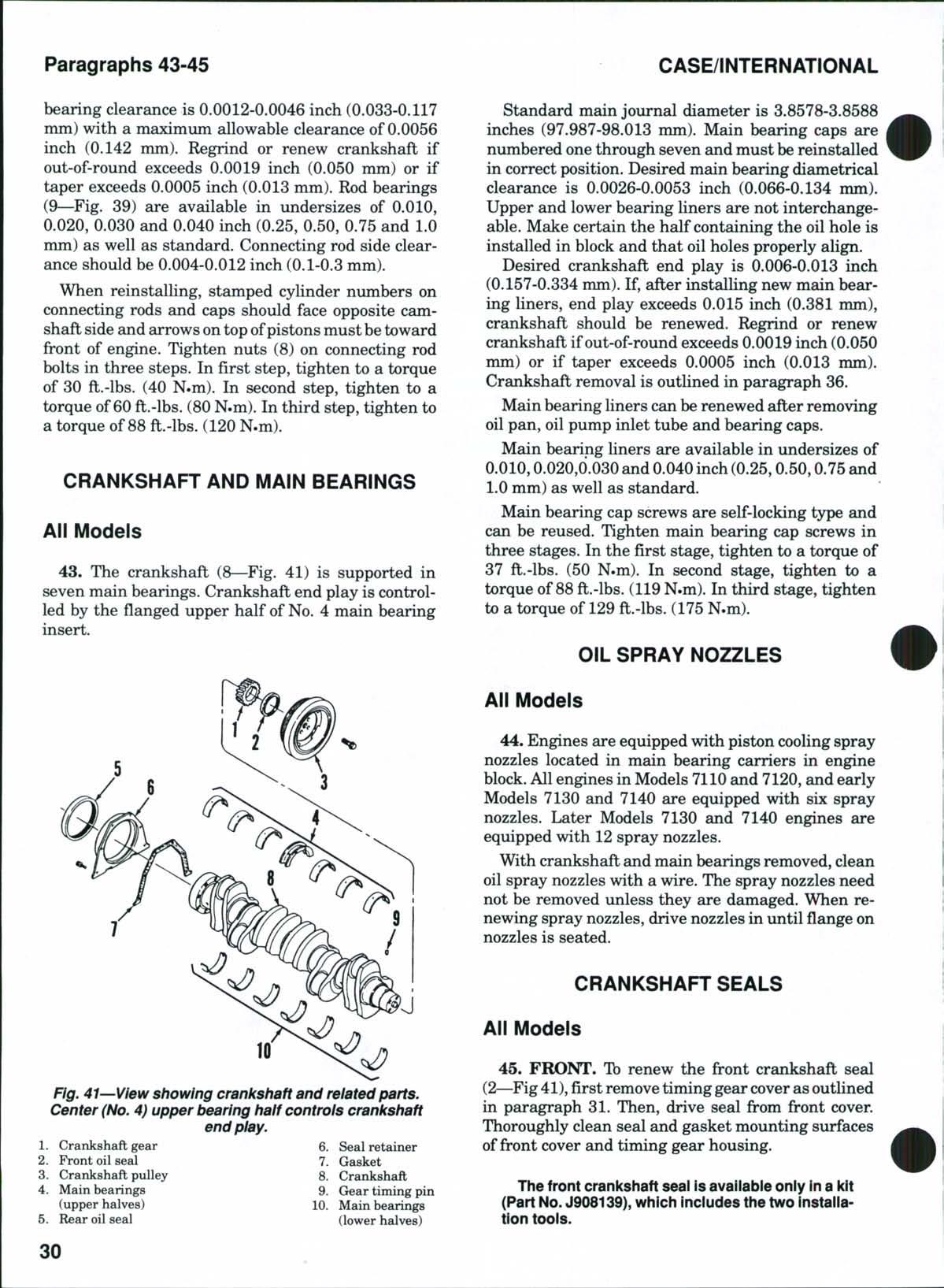
Fig. 41—View showing crankshaft and related parts. Center (No, 4) upper bearing half controls crankshaft end play.
CASE/INTERNATIONAL
Standard main journal diameter is 3.8578-3.8588 inches (97.987-98.013 mm). Main bearing caps are numbered one through seven and must be reinstalled in correct position. Desired main bearing diametrical clearance is 0.0026-0.0053 inch (0.066-0.134 mm). Upper and lower bearing liners are not interchangeable. Make certain the half containing the oil hole is installed in block and that oil holes properly align.
Desired crankshaft end play is 0.006-0.013 inch (0.157-0.334 mm). If, after installing new main bearing liners, end play exceeds 0.015 inch (0.381 mm), crankshaft should be renewed. Regrind or renew crankshaft if out-of-round exceeds 0.0019 inch (0.050 mm) or if taper exceeds 0.0005 inch (0.013 mm). Crankshaft removal is outlined in paragraph 36.
Main bearing liners can be renewed after removing oil pan, oil pump inlet tube and bearing caps
Main bearing liners are available in undersizes of 0.010,0.020,().030 and 0.040 inch (0.25,0.50,0.75 and 1.0 mm) as well as standard.
Main bearing cap screws are self-locking type and can be reused. Tighten main bearing cap screws in three stages. In the first stage, tighten to a torque of 37 ft.-lbs. (50 N.m) In second stage, tighten to a torque of 88 ft.-lbs. (119N.m) In third stage, tighten to a torque of 129 ft.-lbs. (175 N.m)
OIL SPRAY NOZZLES
All Models
44. Engines are equipped with piston cooling spray nozzles located in main bearing carriers in engine block All engines in Models 7110 and 7120, and early Models 7130 and 7140 are equipped with six spray nozzles Later Models 7130 and 7140 engines are equipped with 12 spray nozzles.
With crankshaft and main bearings removed, clean oil spray nozzles with a wire. The spray nozzles need not be removed unless they are damaged. When renewing spray nozzles, drive nozzles in until flange on nozzles is seated
CRANKSHAFT SEALS
All Models
45. FRONT. Tb renew the front crankshaft seal (2—Fig41), first removetiming gear cover as outlined in paragraph 31 Then, drive seal from front cover Thoroughly clean seal and gasket mounting surfaces offront cover and timing gear housing.
The front crankshaft seal isavaiiabie only Ina kit (Part No.J908139), which indudes the two installation toois.
Install two guide studs in the timing gear housing and using a new gasket, slide cover in place. Install cover retaining bolts, but do not tighten at this time. Install seal drivingtoolover crankshaft and into front cover with small diameter toward the engine. This will center the cover with the crankshaft. Tighten front cover cap screws to a torque of 18 ft.-lbs. (24 N.m) Remove seal driver tool Place new seal on the seal protective tool. Apply Loctite 277 to outer diameter of seal Slide protective sleeve tool and seal on crankshaft until seal contacts the cover Remove protective sleeve and install seal driver tool Drive seal inward until outside diameter of installing tool contacts front cover This will be the correct installation depth for the seal Remove seal driver tool If sealing surface on crankshaft is worn or pitted, a wear ring and installing tool kit (Part No J908277) is available for installation
For the balance of reassembly, refer to paragraph 3L
46 REAR Torenew rear crankshaft seal (5—Fig 41), first split tractor between engine and speed transmission housing as outlined in paragraph 24 Drain oil, then unbolt and remove oil pan Refer to Fig 42 and remove drive plate (1),fl3rwheel(2),flywheelhousing(3)and "O" ring (6) Unbolt and remove retainer (6—Fig 41) with seal (5), then remove seal from retainer Clean gasket surfaces of retainer and crankcase Use Loctite safety solvent and clean mounting surface of seal in retainer
NOTE: The rear crankshaft seal is avaiiabie oniy in a kit (Part No. J909410), which inciudes two instailation toois.
Install two guide studs in rear of crankcase Using a new gasket, slide seal retainer in place over guide studs Install retainer bolts, remove guide studs, but do not tighten retainer bolts at this time. Install seal driver tool into seal retainer with small diameter toward engine. This will center the retainer with the crsinkshaft. Tighten seal retainer cap screws to a torque of 7 ft.-lbs. (9 N.m) Remove seal driver tool Slide protective sleeve tool with new seal over crankshaft until outer diameter of seal contacts seal retainer Remove protective sleeve and install seal driver with small diameter toward the seal. Coat outer diameter of seal with soap. Drive seal inward until outer dieimeter of installing tool contacts seal retainer This willbe the correct installation depth for the seal Remove seal driver tool
If sealing surface on crankshaft is wom or pitted, a wear ring and installing tool kit (Part No J906081) is available for installation.
Usenew "O" ring (6—Fig. 42)and reinstallfljnvheel housing. Tighten fl3rwheel housing bolts to a torque of 45 ft.-lbs. (60 N.m). Install flywheel and tighten bolts to a torque of 101ft.-lbs.(137N.m). Install drive
plate and tighten cap screws to a torque of 69-78 ft.-lbs. (94-106 N.m). Use new gasket and reinstall oil pan.
Refer to paragraph 24 and reconnect tractor.
FLYWHEEL
All Models
47 To remove the flywheel (2—Fig 42), first split tractor between engine and speed transmission housing as outlined in paragraph 24 Remove drive plate (1), then unbolt and remove flywheel.
The flywheel ring gear is a shrink fit on front of flywheel. The manufacturer cautions against the use of a torch or open flame for heating ring gear. Heat the new ring gear to 400°-450° F (204°-232° C) in oil or in an oven. Install gear on flywheel.
WARNiNG: Always wear heat protective gloves when handiing heated parts.
Install flywheel and tighten the retaining cap screws to a torque of 101 ft.-lbs. (137 N.m). Reassemble tractor by reversing disassembly procedure.
OIL PAN AND OIL INLET TUBE
All Models
48 Tb remove the oil pan, remove drain plug and drain engine oil On models equipped with frontwheel drive, remove front drive shaft shield and drive

Fig, 42—View of flywheel housing and related parts,
Drive plate , 4 "O" ring 2. Flywheel 5. Flywheel rotating hole plug
Flywheel housing 6 "O** ring
Paragraphs 49-50
shaft as outlined in paragraph 12 Unbolt and remove oil pan, then unbolt and remove oil inlet tube
Clean all surfaces offoreign material Make certain that strainer screen on inlet tube is clean Using new gasket, install oilinlet tube Tighten retaining screws to a torque of 7 ft.-lbs. (9 N.m) Install oil pan with new gasket and tighten cap screws to a torque of 18 ft.-lbs. (24 N.m)
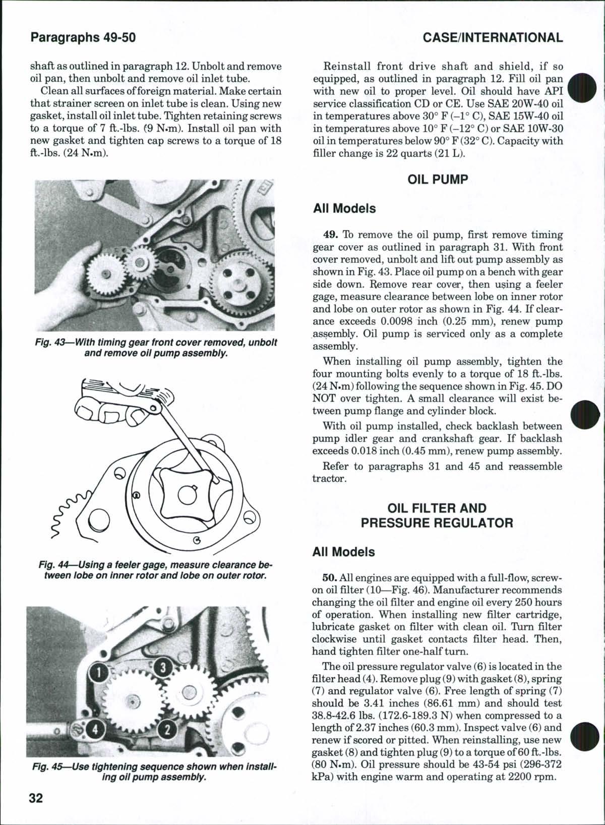
Reinstall front drive shaft and shield, if so equipped, as outlined in paragraph 12 Fill oil pan with new oil to proper level Oil should have API service classification CD or CE Use SAE 20W-40 oil in temperatures above 30° F (-1° C), SAE 15W-40 oil in temperatures above 10° F (-12° C) or SAE lOW-30 oilin temperatures below 90°F (32° C) Capacity with filler change is 22 quarts (21L)
OIL PUMP
All Models
49. To remove the oil pump, first remove timing gear cover as outlined in paragraph 31. With front cover removed, unbolt and lift out pump assembly as shown in Fig.43. Place oil pump on a bench with gear side down. Remove rear cover, then u^ing a feeler gage, measure clearance between lobe on inner rotor and lobe on outer rotor as shown in Fig. 44. If clearance exceeds 0.0098 inch (0.25 mm), renew pump assembly. Oil pump is serviced only as a complete assembly.
When installing oil pump assembly, tighten the four mounting bolts evenly to a torque of 18 ft.-lbs. (24N.m)following the sequence shown in Fig 45 DO NOT over tighten A small clearance will exist between pump flange and cylinder block
With oil pump installed, check backlash between pump idler gear and crankshaft gear. If backlash exceeds 0.018 inch (0.45 mm),renew pump assembly. Refer to paragraphs 31 and 45 and reassemble tractor
OIL FILTER AND PRESSURE REGULATOR
All Models
50.Allengines are equipped with a full-flow, screwon oil filter (10—Fig. 46).Manufacturer recommends changing the oil filter and engine oil every 250 hours of operation. When installing new filter cartridge, lubricate gasket on filter with clean oil Turn filter clockwise until gasket contacts filter head Then, hand tighten filter one-half turn
The oil pressure regulator valve (6)is located in the filter head (4) Removeplug(9) with gasket (8), spring (7) and regulator valve (6) Free length of spring (7) should be 3.41 inches (86.61 mm) and should test 38.8-42.6 lbs. (172.6-189.3 N) when compressed to a length of2.37 inches (60.3mm). Inspect valve (6) and renew if scored or pitted. When reinstalling, use new gasket (8)and tighten plug (9) to a torque of60 ft.-lbs. (80 N.m) Oil pressure should be 43-54 psi (296-372 kPa) with engine warm and operating at 2200 rpm
Fig, 43—With timing gear front cover removed, unbolt and remove oil pump assembly.
Fig. 44^-Using a feeier gage, measure clearance between lobe on Inner rotor and lobe on outer rotor.
Fig, 45—Use tightening sequence shown when Installing oil pump assembly.
ENGINE OIL COOLER
All Models

Clean all surfaces of foreign material Cleaning procedure for the oil cooler consists of flushing the oil circuit with clean solvent and removing scale or rust from exterior of cooling plates
Using new gaskets, reinstall by reversing the removal procedure Tighten filter head retaining cap screws (5) to a torque of 18 ft.-lbs. (24 N.m)
51. The engine oil cooler (2—Fig. 46) is located in right side ofengine block behind the oil filter head (4). TD remove the oil cooler, drain cooling system and remove oil filter cartridge. Disconnect the turbocharger oilsupply line. Unbolt and remove filter head (4) and gasket (3) Remove oil cooler (2) and gasket (1).
DIESEL FUEL SYSTEM
Models 7110,7120 and7130areequipped with Robert Bosch Model PS6A injection pumps. Model 7140 is equipped with a Robert Bosch Model PS6MW ii^ection pump. Robert Bosch multihole ii\jector nozzles are used on all models.
FUEL, FUEL FILTERS AND TRANSFER PUMP
All Models
52. FUEL. The manufacturer recommends using a good grade of No 2 diesel fuel, with a Cetane rating of43or better, for normal operation For cold weather operation, Cetane rating should be 45-55 and fuel pour point should be at least -15° F (-26° C)
53. TRANSFER PUMP. A plunger-type fuel transfer pump (7—Fig. 47) is located on left side of cylinder block.This unit pumps the fuel through the two filters and on to the diesel injection pump. The transfer pump is operated by an eccentric lobe on engine camshaft A thumb push button actuates the pump when bleeding air from fuel system
Ib remove the transfer pump, shut ofFfiiel at tank valve and disconnect supply line from pump Disconnect outlet line from pump, remove cap screws(6) and withdraw pump from engine The transfer pump is serviced only as a complete unit
Use new gasket (8) when installing pump and tighten cap screws (6) to a torque of 18 ft.-lbs. (24 N.m).
54. FUEL FILTERS. Filters are the screw-on type (Fig 47) Filters are available in a kit that consists of both units, and both should be renewed every 500 hours of operation or when noticeable loss of power occurs Primary filter (P) is equipped with a water bleed screw Each morning before operating tractor, loosen water bleed screw and drain off anywater from primary filter. Retighten screw. There is also a water drain valve in the bottom ofthefizeltank Open valve
each morning and drain any accumulated water from fuel tank.
Tb renew the filters, first clean filter head, elements and surrounding area Shut off fuel valve at tank and remove water bleed screw from primary filter (P). Using a clamp-type filter wrench, unscrew and remove filters.
46—Exploded view of engine oil cooler, oil filter head and relative components.
Paragraphs 55-57
Lightly oil gaskets on new filters and turn filters clockwise until gaskets contact filter head (3) Then, hand tighten filters one-half to three-quarters of a turn DONOT over tighten Bleed air from system as outlined in paragraph 55
55. BLEED SYSTEM. To bleed fiiel system, make certadn there isfuel in the tank and that shut offvalve
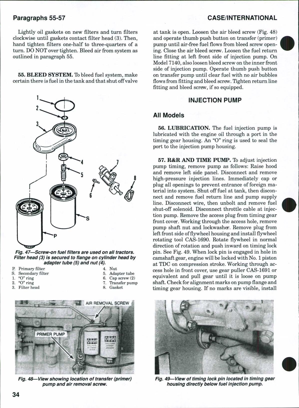
Fig. 47—Screw-on fuel fiiters are used on ali tractors. Fiiter head (3) is secured to flange on cylinder head by adapter tube (5) and nut (4).
Primary filter
at tank is open Loosen the air bleed screw (Fig 48) and operate thumb push button on transfer (primer) pump until air-free fuel flows from bleed screw opening Close the air bleed screw Loosen the fuel return line fitting at left front side of injection pimip On Model 7140,alsoloosen bleed screw on the inner front side of injection pump Operate thumb push button on transfer pump until clear fuel with no air bubbles flows from fitting and bleed screw Tighten return line fitting and bleed screw, if so equipped
INJECTION PUMP
All Models
56. LUBRICATION. The fiiel injection pump is lubricated with the engine oil through a port in the timing gear housing An "O" ring is used to seal the port to the injection pump housing
57. R&R AND TIME PUMP. Tb adjust injection pump timing, remove pump as follows: Raise hood and remove left side panel. Disconnect and remove high-pressure injection lines. Immediately cap or plug all openings to prevent entrance of foreign material into system Shut off fuel at tank, then disconnect and remove fuel return line and pump supply line. Disconnect wire, then unbolt and remove fuel shut-off solenoid. Disconnect throttle cable at injection pump. Remove the access plug from timing gear front cover Working through the access hole, remove pump shaft nut and lockwasher Remove plug from left front side offlywheelhousing and install flywheel rotating tool CAS-1690 Rotate flywheel in normal direction of rotation and push inward on timing lock pin. See Fig. 49. When lock pin is engaged in hole in camshaft gear, engine willbe locked with No. 1 piston at TDC on compression stroke Working through access hole in front cover, use gear puller CAS-1691 or equivalent and pull gear until it is loose on pump shaft. Check for alignment marks onpump flange and timing gear housing. If no marks are visible, install
Fig, 48—View showing iocation of transfer (primer) pump and air removal screw.
4g—Yi0w of timing lock pin iocated in timing gear housing directly below fuel injection pump.
match m£irks for pump alignment. Unbolt and remove injection pump and remove puller from pump drive gear Remove pump timing pin cover (1—Fig 51) and timing pin (3) from left side of pump Rotate pump shaft until the timing tab is visible in timing pin hole Reverse the pin and install with long end inward. See Fig. 50. When slot in long end of timing pin engages tab in pump, injection pump is locked in time for No. 1 cylinder. Install pump timing pin cover and tighten finger tight.
Install new oil port "O" ring (5—Fig 51) and pump flange "O" ring (6) on pump Make certain the timing lock pin is engaged in hole in camshaft gear and that pump timing pin has pump locked in time. Install pump, aligning the match marks on pump flange and timing gear housing. Tighten pump retaining nuts to a torque of 32 ft.-lbs. (43N.m)
NOTE: Inside diameter of pump drive gear is tapered to fit the injection pump siiaft There is no key slot in the pump drive gear.
Install lockwasher (8) and nut (9) on pump shaft Tighten nut a small amount Remove pump timing pin cover (1) and timing pin (3) Reverse the timing pin and install in pump short end first. Use new seal washer (2) and install and tighten timing pin cover to a torque of 11 ft.-lbs. (15 N.m). Pull lock pin out of camshaft gear. Remove flywheel rotation tool and install plug in fljrwheel housing. Then, tighten pump drive gear nut to a torque of 60 ft.-lbs. (81 N.m) on Models 7110, 7120 and 7130 or 66 ft.-lbs. (90 N.m) on Model 7140 Install access plug in timing gear front cover Install fuel shut-off solenoid and throttle cable Install fuel return line and fuel supply line. Install high-pressure injection lines. Turn fdel shut-off valve at tank fiilly on, then bleed fuel system as outlined in paragraph 55.
58. PUMP SPEED ADJUSTMENT. The diesel governor is an integral part of injection pump and.
except for minor speed adjustments, governor service should be done at an authorized diesel service shop Recommended governed speeds for all models are as follows:
Low idle
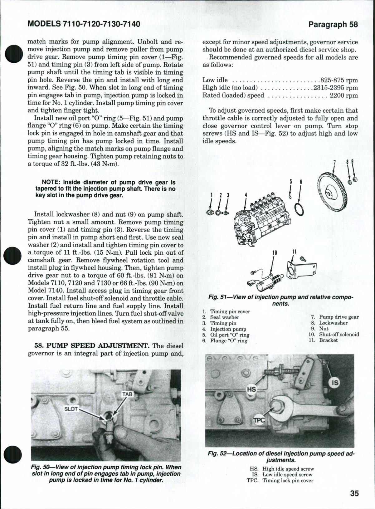
825-875 rpm
idle (no load) 2315-2395 rpm Rated (loaded) speed 2200 rpm
To adjust governed speeds, first make certain that throttle cable is correctly adjusted to fully open and close governor control lever on pump Turn stop screws (HS and IS—Fig 52) to adjust high and low idle speeds
Fig. 51 View of injection pump and reiative components.
Fig. 50--View of injection pump timing lock pin. When slot In long end of pin engages tab in pump. Injection pump is locked in time for No, 1 cylinder.
Fig. 52—Location of diesel Injection pump speed adjustments.
CLICK HERE TO DOWNLOAD THE COMPLETE MANUAL
• Thank you very much for reading the preview of the manual.
• You can download the complete manual from: www.heydownloads.com by clicking the link below
• Please note: If there is no response to CLICKING the link, please download this PDF first and then click on it.
CLICK HERE TO DOWNLOAD THE
NOTE: Adjustment of fuel pump beyond factory specifications wili void the warranty on tractor.
INJECTOR NOZZLES
All Models
All tractors Eire equipped with Robert Bosch fuel injectors shown in Figs. 53 and 54.
59. LOCATING AFAULTYNOZZLE. If rough or uneven engine operation or misfiring indicate a faulty injector, defective unit can usually be located as follows:
With engine operating at speed where malfunction is most noticeable (usually slow-idle speed), loosen
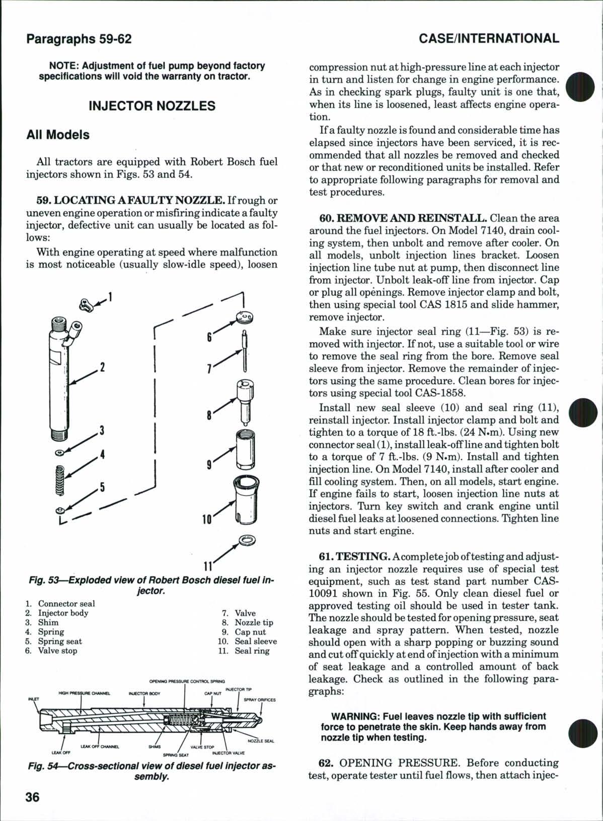
compression nut at high-pressure line at each injector in turn and listen for change in engine performance As in checking spark plugs, faulty unit is one that, when its line is loosened, least affects engine operation.
If afaulty nozzle isfound and considerable time has elapsed since injectors have been serviced, it is recommended that all nozzles be removed and checked or that new or reconditioned units be installed Refer to appropriate following paragraphs for removal and test procedures.
60. REMOVEAND REINSTALL. Clean the area around the fuel injectors On Model 7140, drain cooling system, then ixnbolt and remove after cooler On all models, unbolt injection lines bracket Loosen injection line tube nut at pump, then disconnect line from injector. Unbolt leak-off line from injector. Cap or plug all openings. Remove injector clamp and bolt, then using special tool CAS 1815 and slide hammer, remove injector.
Make sure injector seal ring (11—Fig 53) is removed with injector If not, use a suitable tool or wire to remove the seal ring from the bore Remove seal sleeve from injector. Remove the remainder of injectors using the same procedure. Clean bores for injectors using special tool CAS-1858.
Install new seal sleeve (10) and seal ring (11), reinstall injector Install injector clamp and bolt and tighten to a torque of 18 ft.-lbs. (24 N.m). Using new connector seal (1), install leak-offline and tighten bolt to a torque of 7 ft.-lbs. (9 N.m). Install and tighten injection line. On Model 7140,install after cooler and fillcooling system Then, on all models, start engine If engine fails to start, loosen injection line nuts at injectors Turn key switch and crank engine until diesel fuel leaks at loosened connections. Tighten line nuts and start engine.
61. TESTING.Acompletejoboftestingand adjusting an injector nozzle requires use of special test equipment, such as test stand part number CAS10091 shown in Fig 55 Only clean diesel fuel or approved testing oil should be used in tester tank The nozzle should be tested for openingpressure, seat leakage and spray pattern. When tested, nozzle should open with a sharp popping or buzzing sound and cut offquickly at end ofinjection with a minimum of seat leakage and a controlled amount of back leakage Check as outlined in the following paragraphs:
WARNING: Fuei ieaves nozzie tip with sufficient force to penetrate the sicin. Keep hands away from nozzie tip when testing.
62. OPENING PRESSURE. Before conducting test, operate tester until fuel flows, then attach injec-
Fig. 53—Exploded view of Robert Bosch diesel fuel Injector.
Fig. 54 Cross-sectional view of diesel fuel Injector assembly.
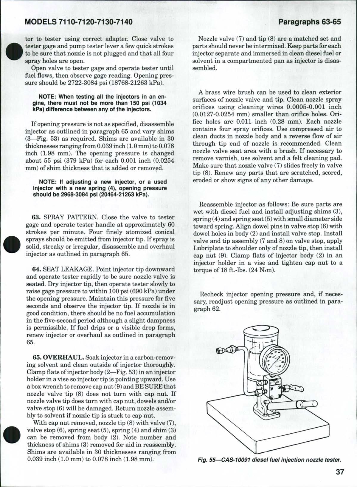
tor to tester using correct adapter Close valve to tester gage and pump tester lever a few quick strokes to be sure that nozzle is not plugged and that all four spray holes are open
Open valve to tester gage and operate tester until fuel flows, then observe gage reading Opening pressure should be 2722-3084 psi (18768-21263 kPa)
NOTE: When testing ail the injectors in an engine, there must not be more than 150 psi (1034 kPa) difference between any of the injectors
If opening pressure is not as specified, disassemble injector as outlined in paragraph 65 and vary shims (3—Fig 53) as required Shims are available in 30 thicknesses ranging from 0.039 inch (1.0mm)to 0.078 inch (1.98 mm) The opening pressure is changed about 55 psi (379 kPa) for each 0.001 inch (0.0254 mm) of shim thickness that is added or removed
NOTE: if adjusting a new injector, or a used injector with a new spring (4), opening pressure shouid be 2968-3084 psi (20464-21263 icPa)
63. SPRAY PATTERN. Close the valve to tester gage and operate tester handle at approximately 60 strokes per minute. Four finely atomized conical sprays should be emitted from injector tip. If spray is solid, streaky or irregular, disassemble and overhaul injector as outlined in paragraph 65.
64 SEAT LEAKAGE Point injector tip downward and operate tester rapidly to be sure nozzle valve is seated. Dry injector tip, then operate tester slowly to raise gage pressure to within 100psi (690 kPa) under the opening pressure. Maintain this pressure for five seconds and observe the injector tip. If nozzle is in good condition, there should be no fuel accumulation in the five-second period although a slight dampness is permissible. If fuel drips or a visible drop forms, renew injector or overhaul as outlined in paragraph 65.
65. OVERHAUL. Soak injector in a carbon-removing solvent and clean outside of injector thoroughly Clamp flats ofinjector body (2—Fig 53)in an injector holder in a vise soinjector tip is pointing upward Use a boxwrench toremove capnut (9) and BE SURE that nozzle valve tip (8) does not turn with cap nut. If nozzle valve tip does turn with cap nut, dowels and/or valve stop (6) will be damaged. Return nozzle assembly to solvent if nozzle tip is stuck to cap nut. With cap nut removed, nozzle tip (8)with valve (7), valve stop (6), spring seat (5), spring (4) and shim (3) can be removed from body (2). Note number and thickness of shims (3) removed for aid in reassembly. Shims are available in 30 thicknesses ranging from 0.039 inch (1.0 mm) to 0.078 inch (1.98 mm).
Nozzle valve (7) and tip (8) are a matched set and parts should never beintermixed. Keep parts for each injector separate and immersed in clean diesel fuel or solvent in a compartmented pan as injector is disassembled.
A brass wire brush can be used to clean exterior surfaces of nozzle valve and tip. Clean nozzle spray orifices using cleaning wires 0.0005-0.001 inch (0.0127-0.0254 mm) smaller than orifice holes. Orifice holes are 0.011 inch (0.28 mm). Each nozzle contains four spray orifices Use compressed air to clean ducts in nozzle body and a reverse flow of air through tip end of nozzle is recommended Clean nozzle valve seat area with a brush If necessary to remove varnish, use solvent and a felt cleaning pad Make sure that nozzle valve (7) slides freely in valve tip (8) Renew any parts that are scratched, scored, eroded or show signs of any other damage
Reassemble injector as follows: Be sure parts are wet with diesel fuel and install adjusting shims (3), spring (4) and spring seat (5)with small diameter side toward spring. Align dowel pins in valve stop (6) with dowel holes in body (2) and install valve stop. Install valve and tip assembly (7 and 8) on valve stop, apply Lubriplate to shoulder only of nozzle tip, then install cap nut (9) Clamp flats of injector body (2) in an injector holder in a vise and tighten cap nut to a torque of 18 ft.-lbs. (24 N.m).
Recheck injector opening pressure and, if necessary, readjust opening pressure as outlined in paragraph 62.
Fig. 55—CAS'1OO91 diesel fuel injection nozzie tester.
FUEL SHUT-OFF SOLENOID
All Models
66 To remove the fuel shut-off solenoid (10—Fig 51), disconnect electrical plug, then unbolt solenoid from mounting bracket (11).
Reinstall solenoid and tighten retaining bolts securely. Connect electrical plug.
All models are equipped with an automatic shutdown system. If engine oil pressure or transmission oil pressure is too low or if transmission oil temperature or engine coolant temperature is too high, 30 seconds after alarm sounds, current will shut off to solenoid and engine will shut down. Refer to appropriate paragraphs in ELECTRICAL SYSTEM section.
ETHER STARTING AID
All Models
67. On all diesel engines, it may be necessary to use ether as a starting aid at temperatures of20°
C) or lower. Ether can is located in front of tractor radiator
To test the ether spray pattern, disconnect ether spray nozzle from intake manifold. Press ether injector button on dash and observe spray pattern. Agood spray pattern is cone shaped. Dribbling or no spray indicates a blocked spray nozzle or lack of ether pressure. Clean spray nozzle or install new can of ether as needed.
Ib change ether container, loosen adjusting nut until container can beremoved. Install new container in the bail and tighten adjusting nut while guiding container into proper position. Rotate container to make certain it is seated properly in injector body, then firmly tighten adjusting nut
NOTE: in warm temperatures, the base shouid be piaced inthe storage position or anempty ether can shouid be installed in the injector ixxly
DIESEL TURBOCHARGER
A Holset turbocharger is used on all models. Refer to Fig. 56. The unit mounts on exhaust manifold and uses exhaust pressure to slightly compress the intake air.
All Models
68. OPERATION. Exhaust gas energy turns the turbine wheel at varying speeds ranging from a few thousand to 125,000 rpm, depending on engine speed and load The compressor wheel supplies air to the intake manifold (6—Fig 56) on Models 7110, 7120 and 7130 or to the after cooler (1) on Model 7140 at or above normal atmospheric pressure. The additional air entering combustion chamber permits an increase in amount of fuel burned, and increased power output over an engine of comparable size not so equipped
The use ofengine exhaust to power the compressor increases engine flexibility, enabling it to perform with the economy of a small engine on light loads yet permitting substantial horsepower increase at full load Horsepower loss because of altitude or atmospheric pressure changes is also largely eliminated Turbine shaft bearings are floating sleeve type and unit is lubricated and cooled by a flow of engine oil under pressure.
All diesel engines operate with an excess of air under light loads In a naturally aspirated engine
most of the air is used at full load and increasing amount of fuel results in a higher smoke level with little increase in power output Turbocharging provides a variation of air delivery and a turbocharged engine operates with an excess of air up to or beyond designed capacity of engine When more fuel is provided, the turbocharger speed and air delivery increase, resulting in additional horsepower and heat with little change in smoke level Smoke, therefore, cannot beused as an accurate guide to safe maximum fiielsetting for a turbocharged engine Refer to appropriate following paragraphs for R&R and overhaul procedures
69. REMOVE AND REINSTALL. Tbremove the turbocharger (11—Fig.56), first raise hood and remove side panels Disconnect air cleaner restriction sending unit wire. Disconnect air tubes, then unbolt and remove strata tube and air cleaner assembly. Loosen clamps on aspirator tube coupling and remove the tube Remove pyrometer from exhaust elbow (8) Disconnect exhaust tubes, then unbolt and remove muffler assembly Unbolt and remove air cleaner and muffler support Disconnect oil supply and drain tubes from turbochargo", then unbolt and remove turbocharger from exhaust manifold (13).
When reinstalling, use new gasket (14) and tighten turbocharger mounting nuts to a torque of 24 ft.-lbs. (32N.m). Install new gasket on oil drain line (12) and
tighten bolts to a torque of 18 ft.-lbs. (24N.m). Install oil supply tube (10) and tighten securely. Complete installation by reversing removal procedure.
Turbocharger MUST be primed after installation as follows: Disconnect plug for fuel shut-off solenoid wire. Turn key switch and crank engine for approximately 30 seconds. Reconnect solenoid wire and set speed control lever to one-third speed position. Start engine and operate at 1000 rpm for about two minutesto supply normal lubrication tothe turbocharger. Then, increase engine speed to 1800rpm until normal oil pressure indicator assures proper oil pressure
70. OVERHAUL. With turbocharger removed as outlined in paragraph 69, place match marks across compressor housing (1—Fig. 57) and back plate (5), across back plate and center housing (15) and across center housing and turbine housing (21) for aid in correct assembly
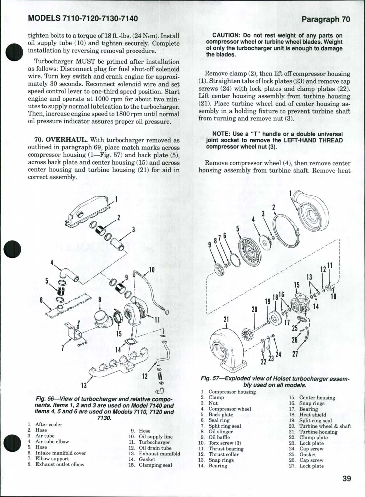
CAUTION: Do not rest weight of any parts on compressor wiieei or turbine wheei blades. Weight of only the turbocharger unit is enough to damage the blades
Remove clamp (2), then lift off compressor housing (1) Straighten tabs oflock plates (23) and remove cap screws (24) with lock plates and clamp plates (22) Lift center housing assembly from turbine housing (21) Place turbine wheel end of center housing assembly in a holding fixture to prevent turbine shaft from turning and remove nut (3)
NOTE: Use a "T" iiandle or a double universal joint socket to remove the LEFT-HAND THREAD compressor wheei nut (3).
Remove compressor wheel (4), then remove center housing assembly from turbine shaft Remove heat
Fig. 56—View of turbocharger and relative components. Items 1,2 and 3 are used on Model 7140 and Items 4, 5 and 6 are used on Models 7110, 7120 and 7130.
After cooler
Fig. 57'-Exploded view ofHolset turbocharger assembly used on all models.
wheel
shield (18) and split seal ring (19) from turbine shaft Straighten tabs oflock plates (27),remove cap screws (26)and lockplates,then remove center housing from back plate (5)
Remove oil baffle (9) and seal ring (6) from back plate Remove oil slinger (8) from back plate and split seal ring (7)fromoilslinga" RemoveTbrxhead screws (10), then remove thrust bearing (11) and thrust collar (12) Remove outer snap rings (13and 16) from each end ofcenter housing and using a wirehook, pull bearings (14 and 17) from center housing Remove inner snap rings (13 and 16) from housing.
Clean all parts in a suitable carbon-softening solvent Astiff brush and plastic or wood scraper should he used after deposits have softened When cleaning, use extreme caution to prevent parts from being nicked, scratched or bent
Inspect turbine housing (21) outlet opening for warping or cracking. Check compressor housing (1) and back plate (5) for wheel friction wear. Inspect turbine shaft for grooves or scratches and turbine wheel and compressor wheel for bent or cracked blades or other damage. Check heat shield (18) and oil slinger (8) for damage and center housing (15) bearing surfaces for scoring or scratches. If any of these parts are damaged, renew turbocharger as they are not serviced separately. A kit consisting of the
following parts is available for cleaning and servicing the turbocharger: nut (3), seal ring (6), split ring seals (7 and 19), Tbrxhead screws (10),thrust bearing (11), snap rings (13 and 16), bearings (14 and 17), lock plates (23 and 27),cap screws (24 and 26) and gasket (25)
Lubricate all parts with clean engine oil and reassemble by reversing the disassembly procedure When installing snap rings (13 and 16), make sure round edge of snap rings face the bearings When installing nut (3), use a double universal joint socket and tighten to a torque of 120 in.-lbs (14N»m) Other tightening torques are as follows: center housing to back plate cap screws (26), 48 in.-lbs (6 N.m); Ibrx head screws (10), 36 in.-lbs. (5 N.m); center housing to turbine housing cap screws (24), 96 in.-lhs. (11 N.m).
With unit reassembled, use a dial indicator and check turbine shaft horizontal end play,which should be 0.0039-0.0063 inch (0.10-0.16 mm) If shaft end play exceeds 0.0063 inch (0.16 mm),thrust collar (12) and/or thrust bearing (11) is worn excessively End play of less than 0.0039 inch (0.10 mm), indicates incomplete cleaning (carbon not all removed) or dirty assembly Unit must be disassembled and recleaned
Reinstall turbocharger, then prime turbocharger as outlined in paragraph 69
AFTER COOLER
Model 7140
71. REMOVE AND REINSTALL. 1b remove the after cooler (4—Fig. 58), drain cooling system and remove air cleaner and muffler. Open drain valve (14) and drain after cooler. Loosen clamps on hoses (1 and 3) and remove air tube (2) Loosen hose clamps and disconnect outlet and inlet tubes (6 and 7) from after cooler Unbolt injection line bracket and support Unbolt and remove after cooler (4) and gasket (12). After cooler can be air checked under water if air pressure is controlled at 18 psi (125 kPa). If air leaks are visible, renew after cooler.
Clean mounting surfaces of after cooler and cylinder head of all foreign material Using a new gasket (12), install after cooler Coat threads of cap screws with Loctiteliquid Teflon, then install and tighten cap screws to a torque of 18 ft.-lbs. (24 N.m). Follow tightening sequence shown in Fig. 59. Complete in-
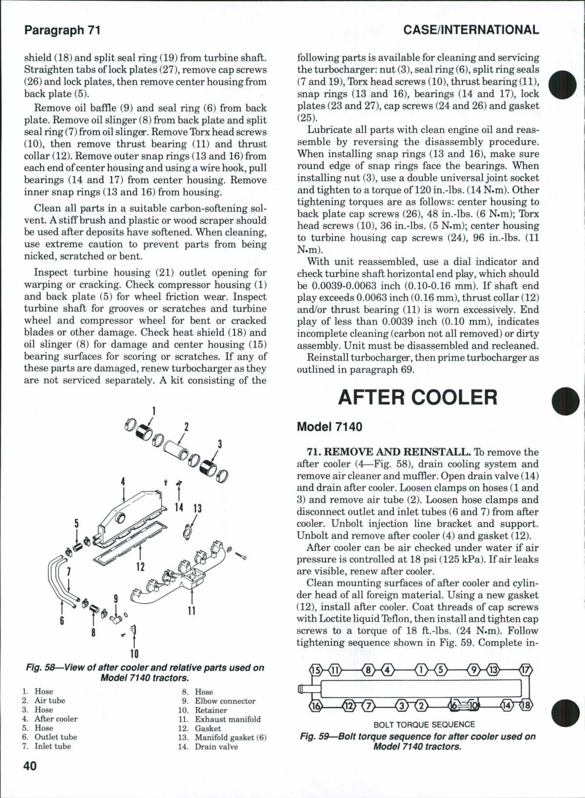
BOLT TORQUE SEQUENCE
Fig. 59—Bolt torque sequence for after cooler used on Model 7140 tractors.
CLICK HERE TO DOWNLOAD THE COMPLETE MANUAL
• Thank you very much for reading the preview of the manual.
• You can download the complete manual from: www.heydownloads.com by clicking the link below
• Please note: If there is no response to CLICKING the link, please download this PDF first and then click on it.
CLICK HERE TO DOWNLOAD THE
stallation by reversing the removal procedure. When refilling cooling system, loosen bleed valve (14) to remove air from after cooler.
AIR CLEANER SYSTEM
All Models
72. FILTERS. All models are equipped with a dry-type air cleaner. See Fig. 60. The secondary (safety) filter should be renewed each 1000 hours of operation DO NOT attempt to clean the secondary element
The large primary filter element can be cleaned by directing compressed air into inside of element. Air pressure must not exceed 35 psi (242 kPa). An element cleaning solution, part No A40910, is available Renew primary element after four cleanings
Tractor is equipped with an air filter restriction switch and warning lamp on the digital instrument cluster, which will indicate when primary element needs servicing.
An aspirated strata tube acts as an air pre-cleaner. Air is sucked from strata tube check valve, along with any dust, then through the aspirator tube to the muffler and out with exhaust gas. Remove the strata tube and blow clean with compressed air regulated at
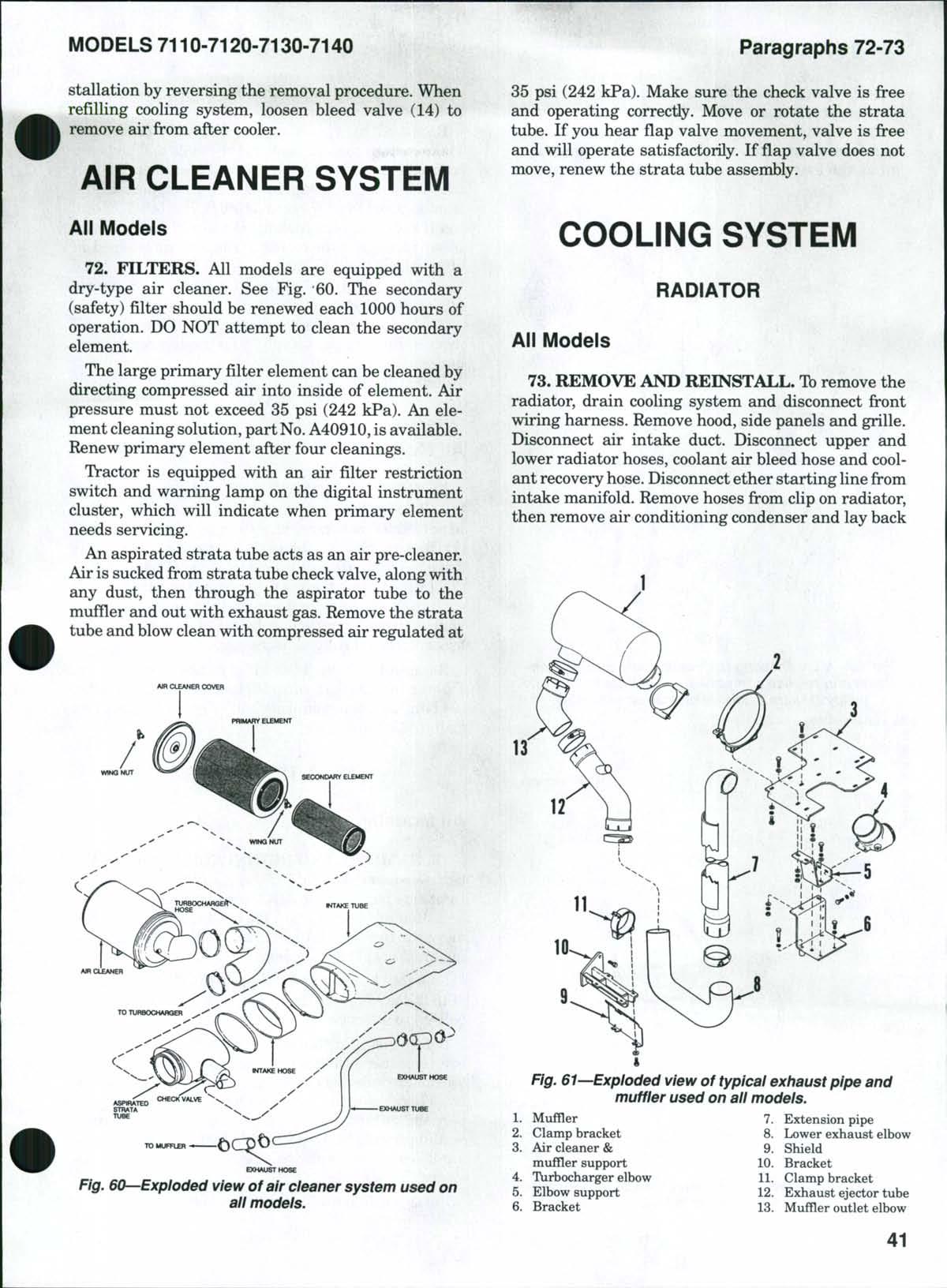
35 psi (242 kPa). Make sure the check valve is free and operating correctly. Move or rotate the strata tube. If you hear flap valve movement, valve is free and will operate satisfactorily. If flap valve does not move, renew the strata tube assembly.
COOLING SYSTEM
RADIATOR
Ali Models
73. REMOVE AND REINSTALL. Toremove the radiator, drain cooling system and disconnect front wiring harness. Remove hood, side panels and grille. Disconnect air intake duct. Disconnect upper and lower radiator hoses, coolant air bleed hose and coolant recovery hose. Disconnect ether starting hne from intake manifold Remove hoses from clip on radiator, then remove air conditioning condenser and lay back
Fig. 60—Exploded view of air cleaner system used on all models.