
SHOP MANUAL CASE/INTERNATIONAL
MODELS 5120, 5130 & 5140
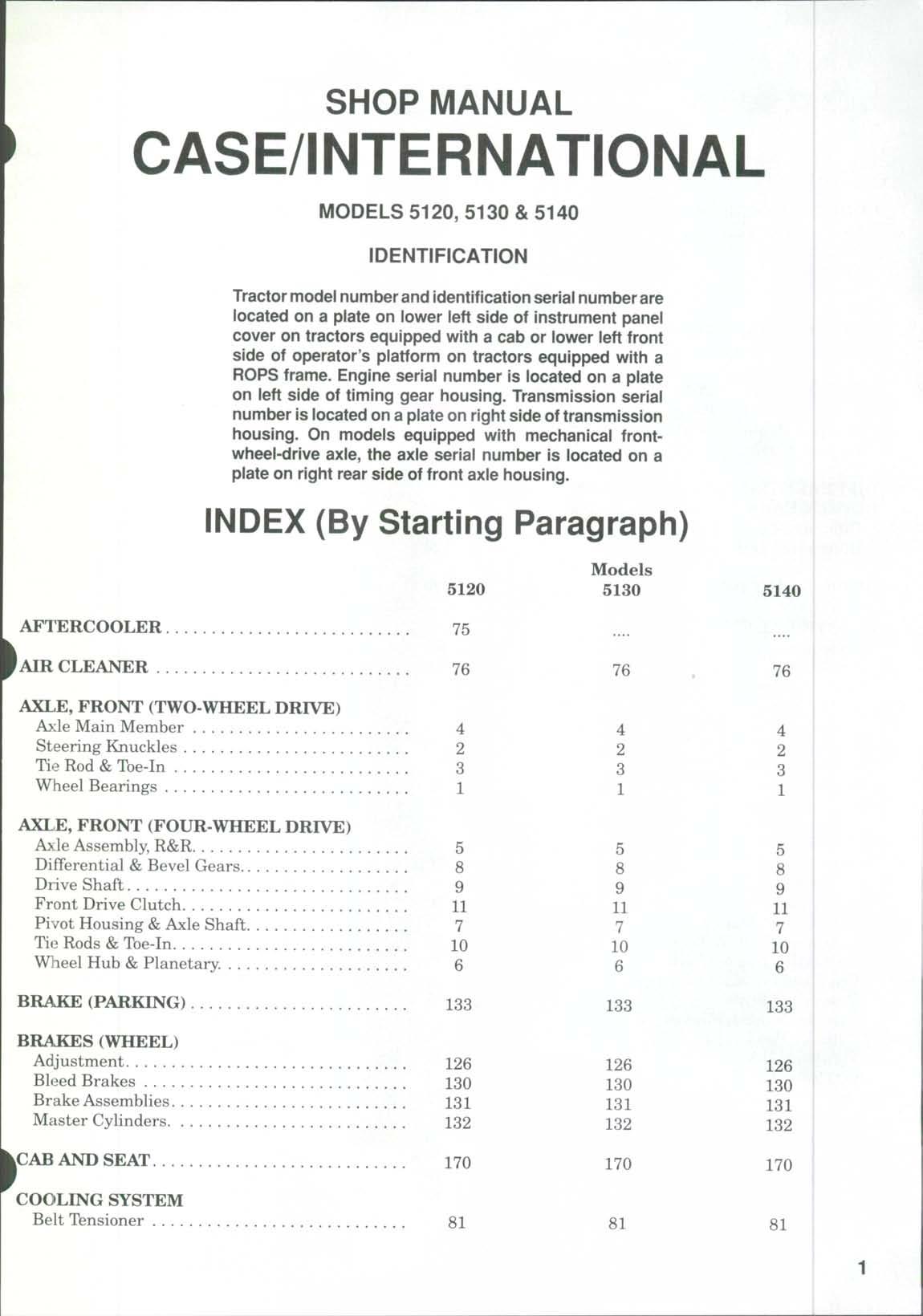
IDENTIFICATION
Tractor modelnumber andidentificationseriai numberare located on a plate on lower ieft side of instrument panel cover on tractors equipped with a cab or lower ieft front side of operator's platform on tractors equipped with a ROPS frame Engine seriai number is located on a plate on left side of timing gear housing. Transmission seriai number is located ona plate on right side of transmission housing. On models equipped with mechanical frontwheel-drive axle, the axie seriai number is located on a plate on right rear side of front axle housing.
INDEX (By Starting Paragraph)
CLICK HERE TO DOWNLOAD THE COMPLETE MANUAL
• Thank you very much for reading the preview of the manual.
• You can download the complete manual from: www.heydownloads.com by clicking the link below

• Please note: If there is no response to CLICKING the link, please download this PDF first and then click on it.
CLICK HERE TO DOWNLOAD THE
INDEX (CONT.)
INDEX (CONT.)
RANGE TRANSMISSION &FORWARDREVERSE SHUTTLE TRANSMISSION Inching Pedal & Transmission
Shuttle Valve
and Overhaul
CONDENSED SERVICE DATA
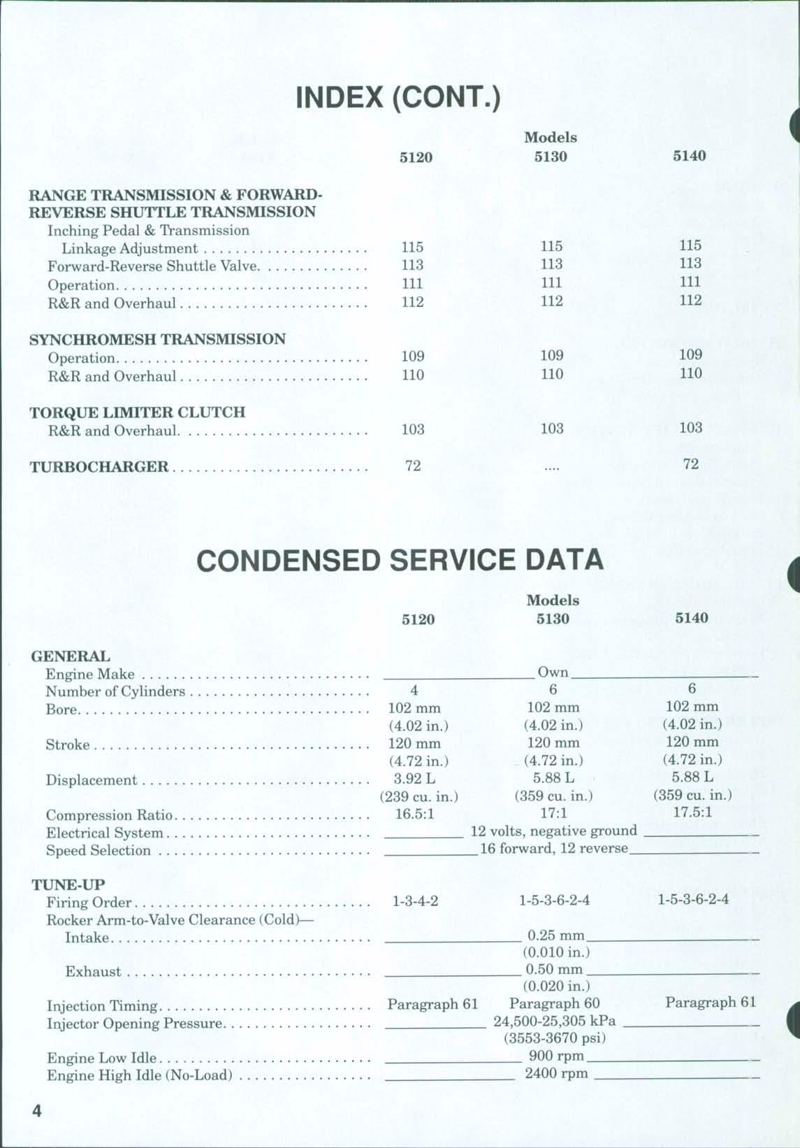
GENERAL
Displacement
(4.72 in.) (4.72 in.)
L
L (239 cu. in.) (359 cu. in.) Compression Ratio
TUNE-UP
(0.010 in.)
mm (0.020 in.)
Injection Timing Paragraph 61 Paragraph 60
Injector Opening Pressure 24,500-25,305 kPa (3553-3670 psi) Engine Low Idle
(4.72 in.)
L (359 cu in.)
Paragraph 61
CONDENSED SERVICE DATA (CONT.)
(Cont.)
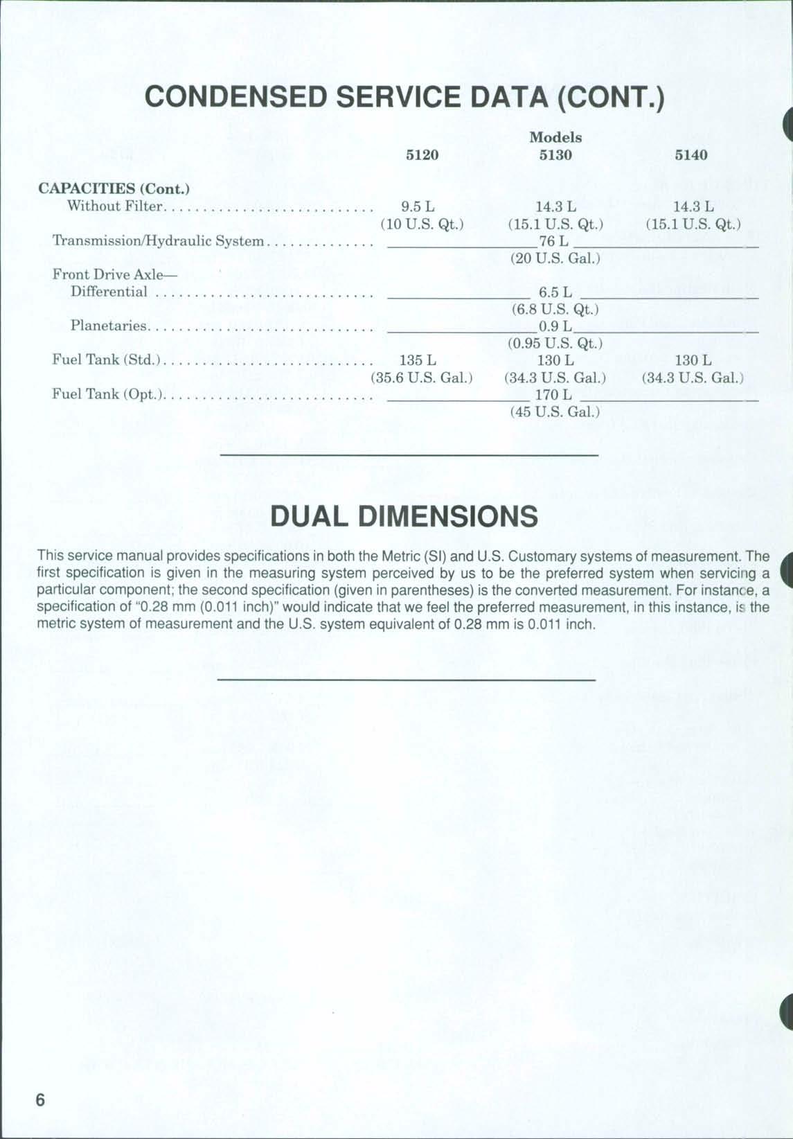
DUAL DIMENSIONS
This service manual provides specifications in both the Metric (SI) and U.S Customary systems of measurement The first specification is given in the measuring systenn perceived tDyus to be the preferred system when servicing a particular component; the second specification (given inparentheses) isthe converted measurement. Forinstanc e,a specification of "0.28 mm (0.011 inch)" would indicate that we feel thepreferred measurement, inthis instance, is the metric system of measurement and the U.S system equivalent of 0.28 mm is 0.011 inch
FRONT AXLE (TWO-WHEEL DRIVE)
FRONT WHEEL BEARINGS
All Models
1 Refer to Fig 1 for typical wheel hub and bearing assembly.
The tapered inner and outer roller bearings (4 and 10) are not interchangeable Clean and inspect bearing cups and cones and renev^ as necessary.
Install inner bearing cone (4) on steering knuckle spindle Install bearing cups (5 and 9) in hub Install oil seal (3) and clamping ring (2) in inner bore of hub Pack bearing cones and fill hub with No 2 lithium base grease. Install hub on steering knuckle, then install outer bearing cone (10), washer (11) and nut (12;'
TD adjust the bearings, tighten nut to a torque of 100 N.m (74 ft.-lbs.) while rotating the hub. Then, back nut off until next cotter pin slot is aligned. Install cotter pin Install and tighten dust cover (13)
Install wheel and tire, and tighten lug nuts (8)to a torque of 300 N.m (220 ft. lbs.).
STEERING KNUCKLES
All models
2.REMOVEAND REINSTALL. To remove either steering knuckle, raise front of tractor and place a stand under axle extension. Remove wheel and tire assembly. Disconnect tie rod ball joint from steering arm (8—Fig 2) and steering cylinder ball joint (13) from right steering arm Support hub and steering knuckle and remove steering arm clamping bolt. Lift off steering arm and shims (9). Lower steering knuckle from axle extension (12)
Remove felt seal (10) and upper bushing (11) from axle extension. Remove lower bushing (17) and thrust bearing (18) from steering knuckle. Split bushings (11 and 17) are not a tight fit in axle extensions If necessary, remove hub and wheel bearings as outlined in paragraph 1
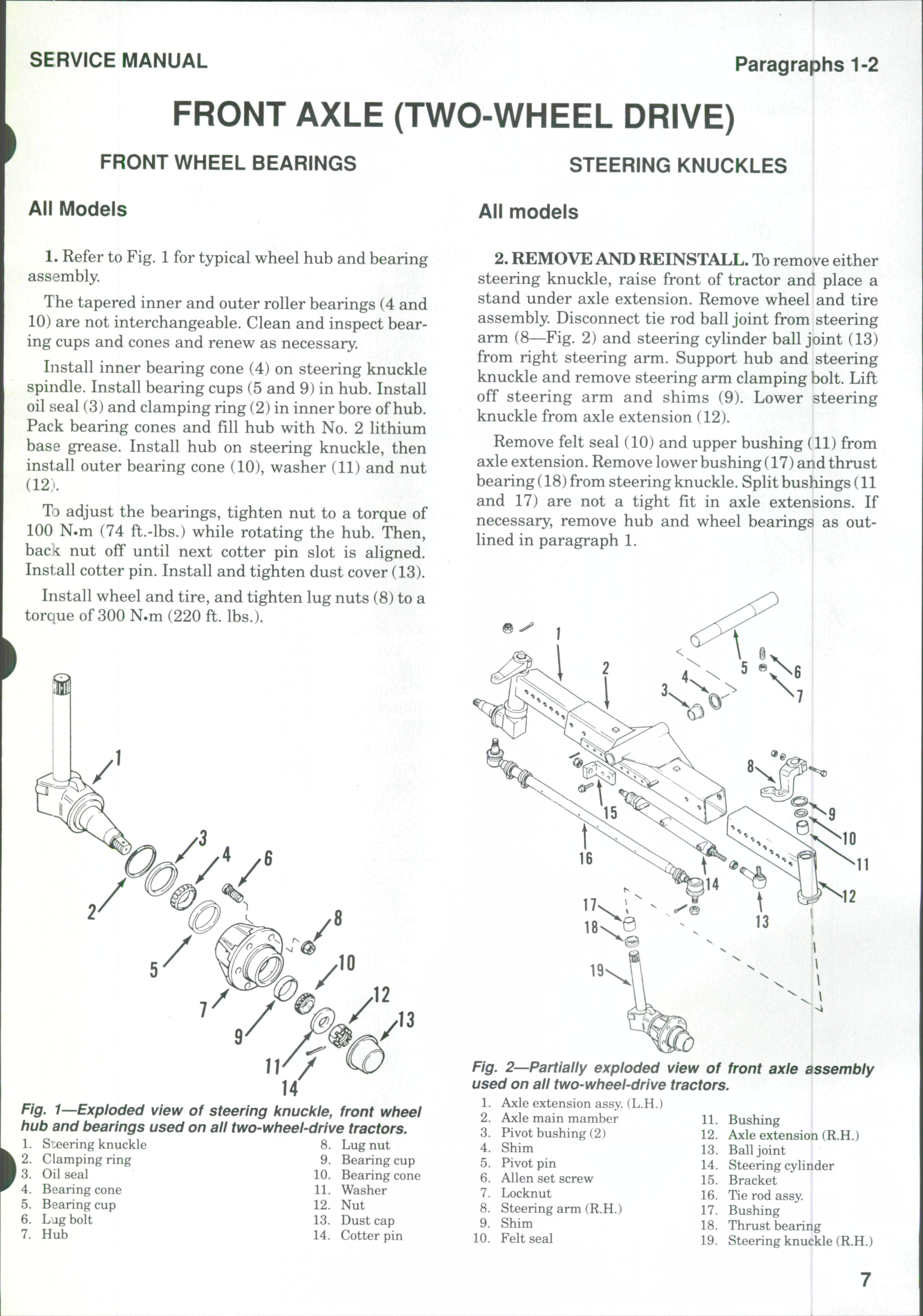
1—Exploded view of steering knuckle, front wheel hub and bearings used on all two-wheel-drive tractors.
S:eering knuckle
Clamping ring
Oil seal
Bearing cone
Fig. 2 Partially exploded view of used on all two-wheel-drive tractors
1 Axle extension assy (L.H.)
2 Axle main mamber 11
3 Pivot bushing (2) 12
4. Shim 13.
5 Pivot pin 14,
6 Allen set screw 15
7 Locknut 16
8. Steering arm (R.H.) 17.
9 Shim 18
10 Felt seal 19
front axle assembly
Bushing Axle extension (R.H.)
Ball joint
Steering cylinder
Bracket
Tie rod assy.
Bushing
Thrust bearing
Steering knuckle (R.H.)
Fig.
Paragraphs 3-4
Clean and inspect all parts and renew as required Reinstall by reversing the removal procedure Add or remove shims (9) to obtain 0.1mm (0.004in.)end play for the steering knuckle Tighten steering arm clamping bolt to a torque of 280 N.m (206 ft.-lbs.)
TIE ROD AND TOE-IN
All Models
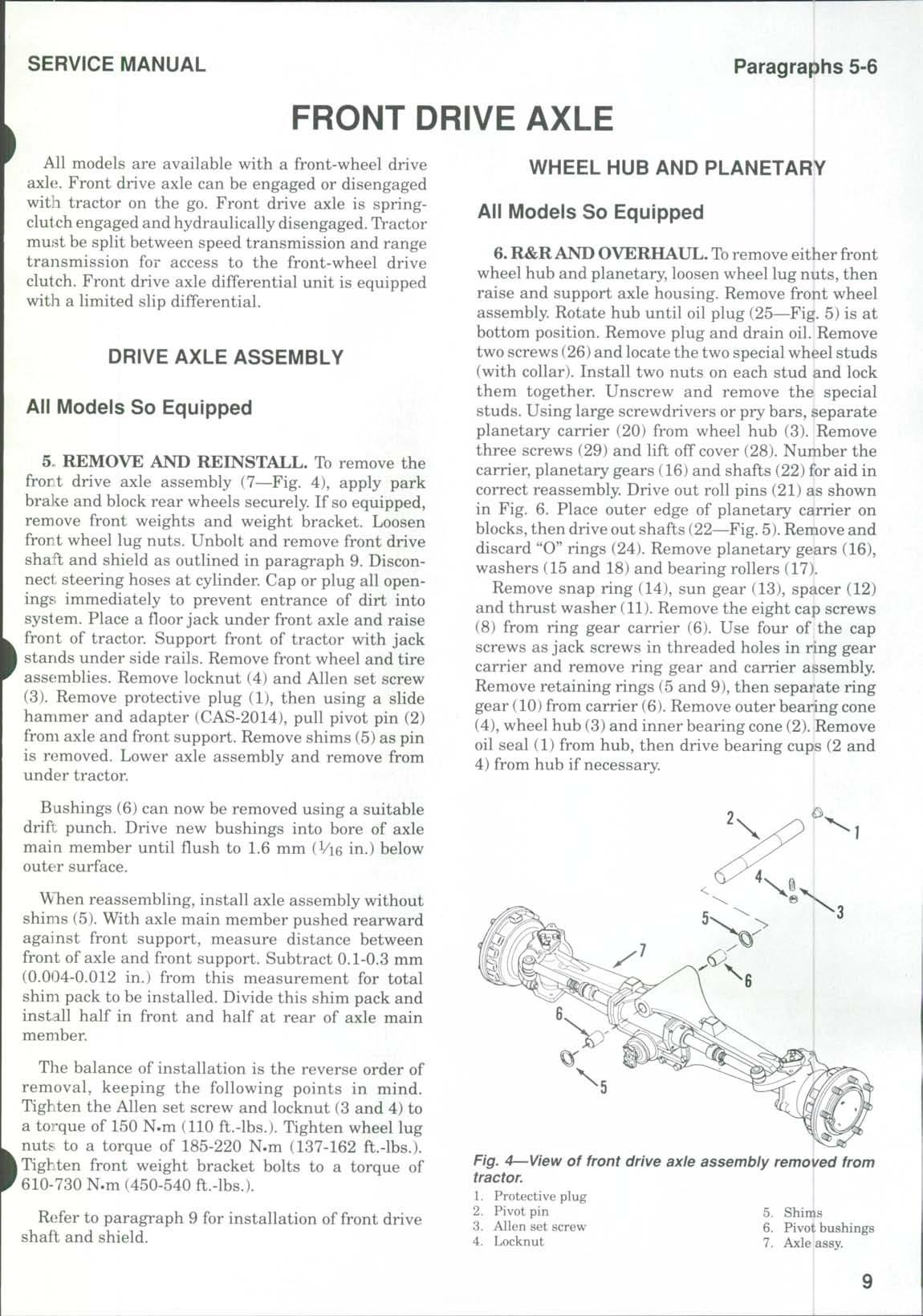
3. Disassembly of the tie rod is obvious after an examination of the unit and reference to Fig 3
Front wheel toe-in should be 2-4 mm (0.080-0.160 in.) To check toe-in, measure the distance between the front wheel rims at the front and at the rear of the wheel rims at hub height The measurement at
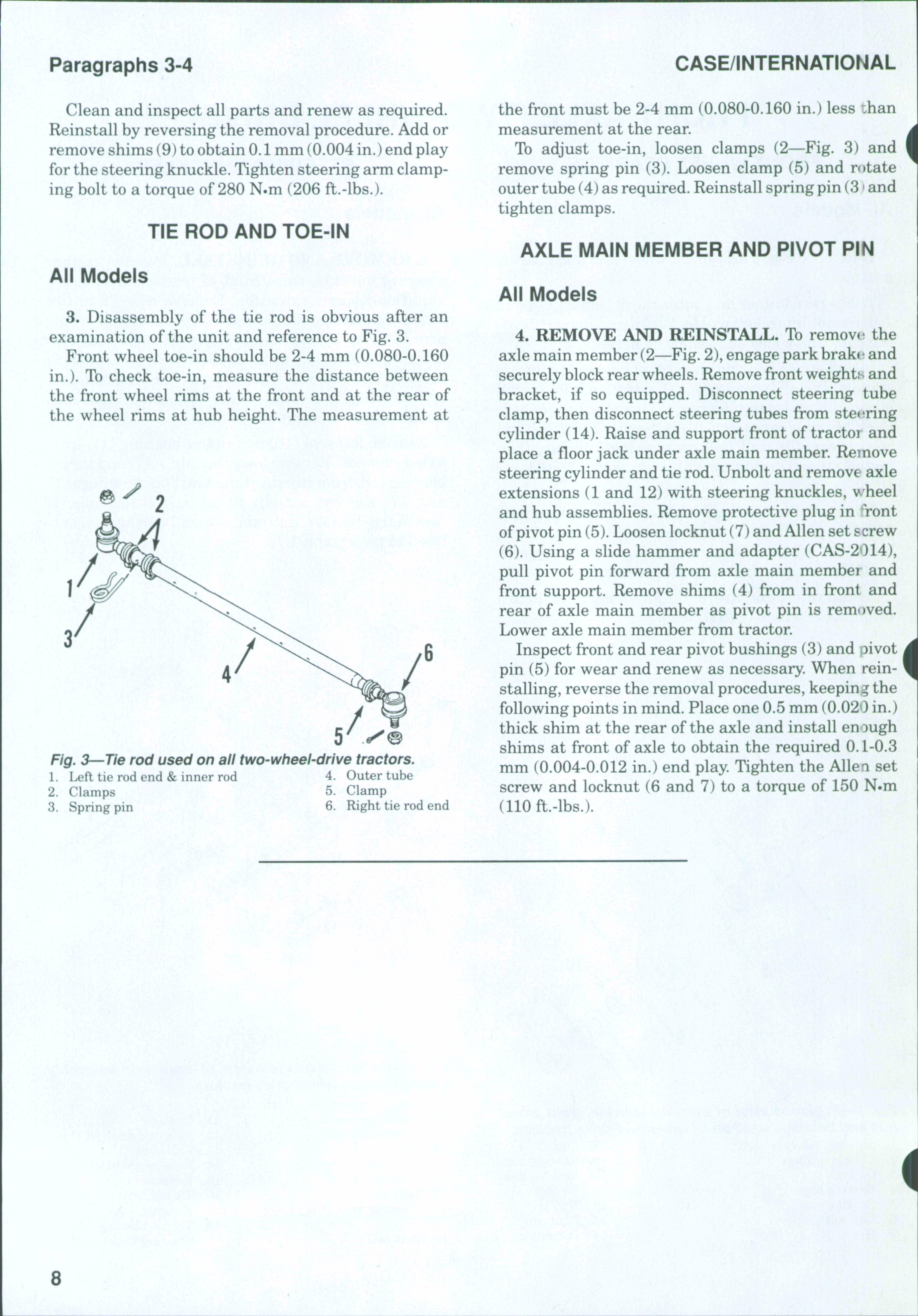
Fig. 3—Tie rod used on all two-wheel-drive tractors.
1 Left tie rod end & inner rod
4 Outer tube
2 Clamps 5 Clamp
3 Spring pin
6 Right tie rod end
the front must be 2-4 mm (0.080-0.160 in.) less ihan measurement at the rear
To adjust toe-in, loosen clamps (2—Fig 3) and remove spring pin (3) Loosen clamp (5) and r(»tate outer tube (4) as required Reinstall spring pin (3 • and tighten clamps.
AXLE MAIN MEMBER AND PIVOT PIN
All Models
4. REMOVE AND REINSTALL. To remove the axle main member (2—Fig 2),engage park brake and securely blockrear wheels Remove front weights and bracket, if so equipped. Disconnect steering tube clamp, then disconnect steering tubes from steering cylinder (14). Raise and support front of tractor and place a floor jack under axle main member. Remove steering cylinder and tie rod. Unbolt and remove axle extensions (1 and 12) with steering knuckles, wheel and hub assemblies. Remove protective plug in *Tont ofpivot pin (5) Loosen locknut (7) and Allen set screw (6) Using a slide hammer and adapter (CAS-2014), pull pivot pin forward from axle main member and front support Remove shims (4) from in front and rear of axle main member as pivot pin is rem<»ved Lower axle main member from tractor Inspect front and rear pivot bushings (3) and pivot pin (5) for wear and renew as necessary. When reinstalling, reverse the removal procedures, keeping the following points in mind. Place one 0.5 mm (0.020 in.) thick shim at the rear of the axle and install enough shims at front of axle to obtain the required 0. L-0.3 mm (0.004-0.012 in.) end play Tighten the Allen set screw and locknut (6 and 7) to a torque of 150 N.m (110 ft.-lbs.)
FRONT DRIVE AXLE
All models are available with a front-wheel drive axle. Front drive axle can be engaged or disengaged with tractor on the go. Front drive axle is springclutch engaged and hydraulically disengaged TVactor must be split between speed transmission and range transmission for access to the front-wheel drive clutch. Front drive axle differential unit is equipped witli a limited slip differential.
DRIVE AXLE ASSEMBLY
All Models So Equipped
5 REMOVE AND REINSTALL. To remove the frort drive axle assembly (7—Fig. 4), apply park bra]i:e and block rear wheels securely. If so equipped, remove front weights and weight bracket Loosen front wheel lug nuts Unbolt and remove front drive shaft and shield as outlined in paragraph 9. Disconnect steering hoses at cylinder. Cap or plug all openings immediately to prevent entrance of dirt into system Place a fioor jack under front axle and raise front of tractor Support front of tractor with jack I stands under side rails. Remove front wheel and tire assemblies. Remove locknut (4) and Allen set screw (3) Remove protective plug (1), then using a slide hammer and adapter (CAS-2014), pull pivot pin (2) from axle and front support Remove shims (5) as pin is removed. Lower axle assembly and remove from under tractor.
Bushings (6) can now be removed using a suitable drift punch. Drive new bushings into bore of axle main member until fiush to 1.6 mm (Vi6 in.) below outeir surface.
When reassembling, install axle assembly without shims (5) With axle main member pushed rearward against front support, measure distance between front of axle and front support Subtract 0.1-0.3 mm (0.004-0.012 in.) from this measurement for total shim pack to be installed. Divide this shim pack and install half in front and half at rear of axle main member
Tlie balance of installation is the reverse order of removal, keeping the following points in mind Tighten the Allen set screw and locknut (3 and 4) to a torque of 150 N.m (110 ft.-lbs.) Tighten wheel lug nuts to a torque of 185-220 N.m (137-162 ft.-lbs.). I Tighten front weight bracket bolts to a torque of 610-730 N.m (450-540 ft.-lbs.)
Refer to paragraph 9 for installation of front drive shaft and shield.
WHEEL HUB AND PLANETARY
All Models So Equipped
6. R&RAND OVERHAUL.To remove either front wheel hub and planetary, loosen wheel lug nuts, then raise and support axle housing Remove front wheel assembly. Rotate hub until oil plug (25—Fig. 5) is at bottom position. Remove plug and drain oil. Remove two screws (26)and locate the two special wheel studs (with collar) Install two nuts on each stud and lock them together Unscrew and remove the special studs. Using large screwdrivers or pry bars, separate planetary carrier (20) from wheel hub (3). Remove three screws (29) and lift off cover (28) Number the carrier, planetary gears (16) and shafts (22) for aid in correct reassembly Drive out roll pins (21) as shown in Fig. 6. Place outer edge of planetary carrier on blocks,then drive out shafts (22—Fig.5).Remove and discard "O" rings (24) Remove planetary gears (16), washers (15 and 18) and bearing rollers (17)
Remove snap ring (14), sun gear (13), spacer (12) and thrust washer (11). Remove the eight cap screws (8) from ring gear carrier (6) Use four of the cap screws as jack screws in threaded holes in ring gear carrier and remove ring gear and carrier assembly Remove retaining rings (5 and 9), then separ'ate ring gear (10) from carrier (6). Remove outer bearing cone (4), wheel hub (3) and inner bearing cone (2) Remove oil seal (1) from hub, then drive bearing cups (2 and 4) from hub if necessary I
Fig. 4—View of front drive axle assembly removed from tractor.
CLICK HERE TO DOWNLOAD THE COMPLETE MANUAL
• Thank you very much for reading the preview of the manual.
• You can download the complete manual from: www.heydownloads.com by clicking the link below
• Please note: If there is no response to CLICKING the link, please download this PDF first and then click on it.
CLICK HERE TO DOWNLOAD THE
Paragraph 7
Clean and inspect all parts and renew any showing excessive wear or other damage. Reinstall by reversing removal procedures keeping the following points in mind: Use new oil seal (1) and "0" rings (24). Tighten ring gear carrier cap screws (8) to a torque of 200 N.m (162 ft.-lbs.). When installing planetary carrier (20) on wheel hub (3), apply Activator (CAS345153) to face of planetary carrier and Sealant (CAS-345152) to face of hub. Within five minutes after assembly, tighten the two special wheel studs to a torque of 70 N.m (51 ft.-lbs.) and the two countersunk screws (26) to a torque of 80 N.m (59 ft.-lbs.) Install cover (28) and tighten the three screws (29) to a torque of 34 N.m (25 ft.-lbs.)
Rotate hub until the word CASE is horizontal, then fill the unit to level plug opening with SAE 85W-140 gear lubricant Capacity is approximately 1.0 liter (1.06 U.S. qt.). Install plug (25). Install wheel and tighten lug nuts to 300 N.m (220 ft.-lbs.) torque
Repeat operation on opposite wheel hub and planetary if necessary
PIVOT HOUSING AND AXLE SHAFT
All Models So Equipped
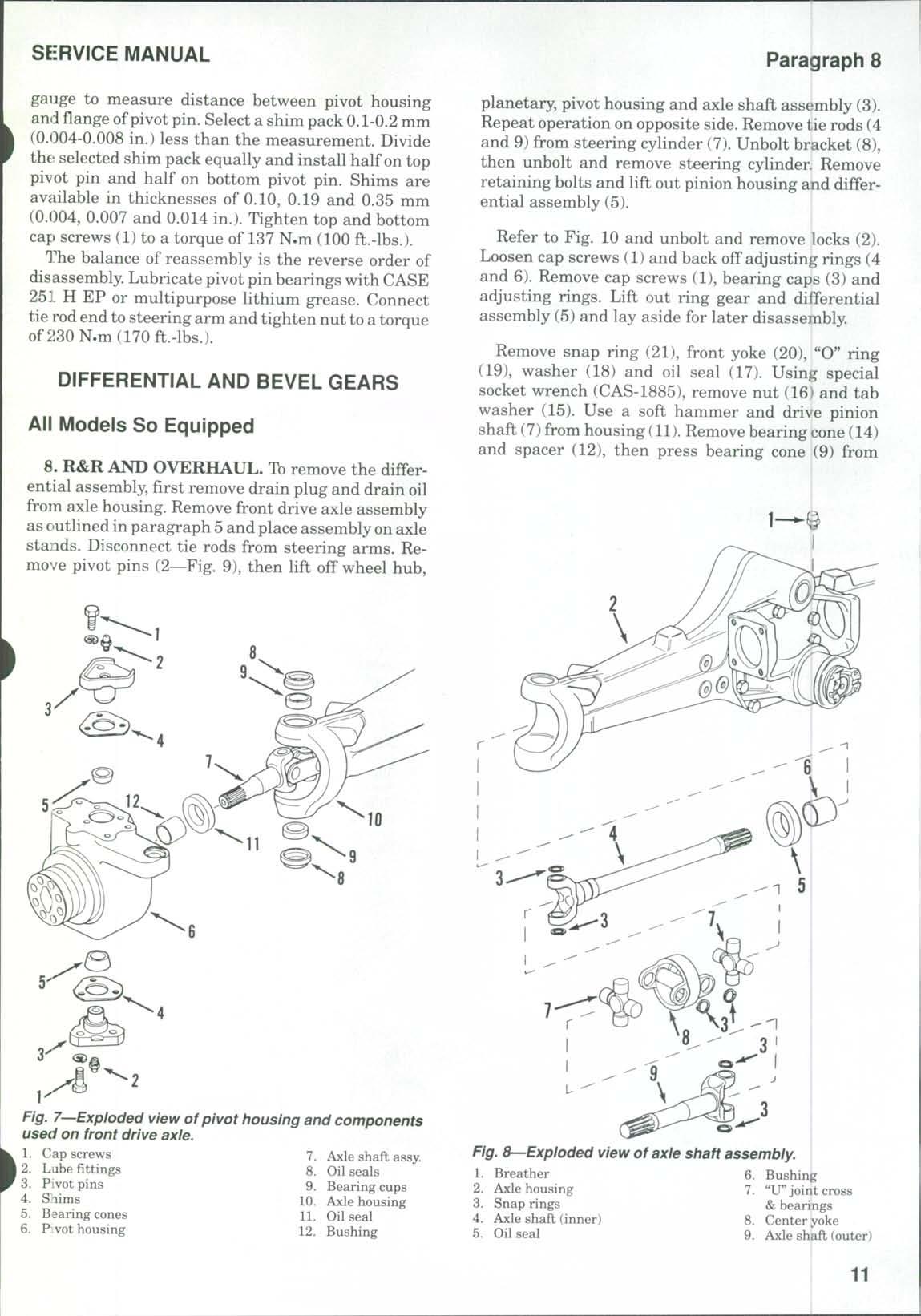
7. REMOVE AND REINSTALL. To removt the pivot housing (6—Fig. 7), first remove the wheel hub and planetary as outlined in paragraph 6. Disconnect tie rod end from steering arm. Remove cap screws (1), then remove pivot pins (3)with shims (4) and bearing cones (5) Lift off pivot housing (6) Remove oil seal (11) and, if necessary, remove bushing (12)from pivot housing Remove oil seals (8) and bearing cups (9) Use a suitable puller toremove bearing cones(5) from pivot pins
Withdraw axle shaft assembly (7) Remove oil seal (5—Fig 8) and, if necessary, remove bushing (6
Clean and inspect all parts and renew any showing excessive wear or other damage. "U" joint cross and bearings (7) are available only as a unit. Renev al of "U"joints is obvious after examination of the assembly and reference to Fig. 8.
When reassembling, use all new oil seals Install seal (5—Fig 8) in axle housing (2), then care fully install axle shaft assembly (7—Fig. 7).Install oi! seal (11) in pivot housing (6). Install bearing cups (9' and oil seals (8) in axle housing (10). Carefully install pivot housing over outer axle shaft and axle housing. Install lower pivot pin (3) with bearing cone (5 , but without shims (4). Tighten lower cap screws (1 to a torque of 83 N.m (60 ft.-lbs.). Install upper pivot pin (3) with bearing cone (5), but without shims (4) Use a jack under lower pivot pin to hold pivot housing upward While holding down on pivot pin,use a feeler
iFig^ e^When disassembling planetary, drive out shaft roll pins as shown.
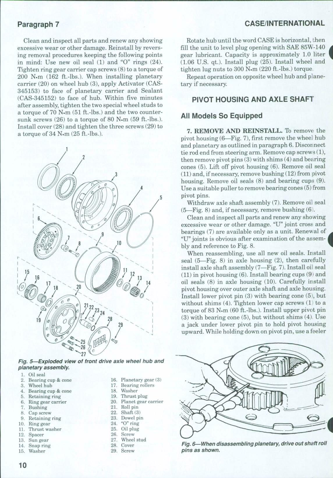
Fig. 5—Exploded view of front drive axle wheel hub
assembly.
gauge to measure distance between pivot housing and fiange ofpivot pin. Select a shim pack 0.1-0.2 mm (0.1)04-0.008 in.) less than the measurement. Divide the selected shim pack equally and install half on top pivot pin and half on bottom pivot pin. Shims are available in thicknesses of 0.10, 0.19 and 0.35 mm (0.004, 0.007 and 0.014 in.) Tighten top and bottom cap screws (1) to a torque of 137 N.m (100 ft.-lbs.)
The balance of reassembly is the reverse order of disassembly Lubricate pivot pin bearings with CASE 251 H EP or multipurpose Hthium grease Connect tie rod end to steering arm and tighten nut to a torque of230 N.m (170 ft.-lbs.)
DIFFERENTIAL AND BEVEL GEARS
All Models So Equipped
8. R&R AND OVERHAUL. To remove the differential assembly, first remove drain plug and drain oil from axle housing Remove front drive axle assembly as outlined in paragraph 5 and place assembly on axle stands Disconnect tie rods from steering arms Remove pivot pins (2—Fig. 9), then lift off wheel hub.
planetary, pivot housing and axle shaft assembly (3). Repeat operation on opposite side. Remove tie rods (4 and 9) from steering cylinder (7) Unbolt bracket (8), then unbolt and remove steering cylinder Remove retaining bolts and lift out pinion housing and differential assembly (5).
Refer to Fig. 10 and unbolt and remove locks (2). Loosen cap screws (1) and back off adjusting rings (4 and 6). Remove cap screws (1), bearing caps (3) and adjusting rings. Lift out ring gear and differential assembly (5) and lay aside for later disassembly.
Remove snap ring (21), front yoke (20), "O" ring (19), washer (18) and oil seal (17) Using special socket wrench (CAS-1885), remove nut (16) and tab washer (15) Use a soft hammer and drive pinion shaft (7)from housing (11) Remove bearing cone (14) and spacer (12), then press bearing cone (9) from
Fig. 7—Exploded view of pivot housing and components used on front drive axle.
Fig. 8—Exploded view of axle shaft assembly.
stant, 109.75 mm (4.32 in.) Then, subtract the measurement etched on pinion shaft in millimeters from the previous sum to obtain the correct thickness of shims (8—Fig. 10)to be installed. Remove the special too] (CAS-1839) and bearing cones Shims are available in ten thicknesses from 2.5-3.4 mm (0.098 to 0.134 in.)
Install the previously determined shim pack (8) on pinion shaft (7). Heat bearing (9) to a temperature of 80-90° C (175-195° F) and install on pinion shaft. Insi:all collapsible spacer (12) on shaft, then install pimon shaft assembly in housing (11). Heat and install bearing cone (14)and install tab washer (15) and a nt^w nut (16). Tighten nut only until shaft end play is removed Use a cord wrapped around splined end ofpinion shaft and a spring scale to measure the force required to rotate the pinion shaft Bearing preload is correct when a spring scale reading of 92-137 N (20.7-30.8 lbs.) is obtained Tighten pinion shaft nut until desired spring scale reading (bearing preload) is obtained When preload is correct, use a hammer
and small punch to stake edge of nut into slot on pinion shaft
NOTE: If the pinion shaft nut isovertightened and the bearing preload exceeds 137 N (30.8 lbs.), disassemble the pinion shaft and install a new collapsible spacer (12) Then, repeat the bearing preload adjustment procedure. |
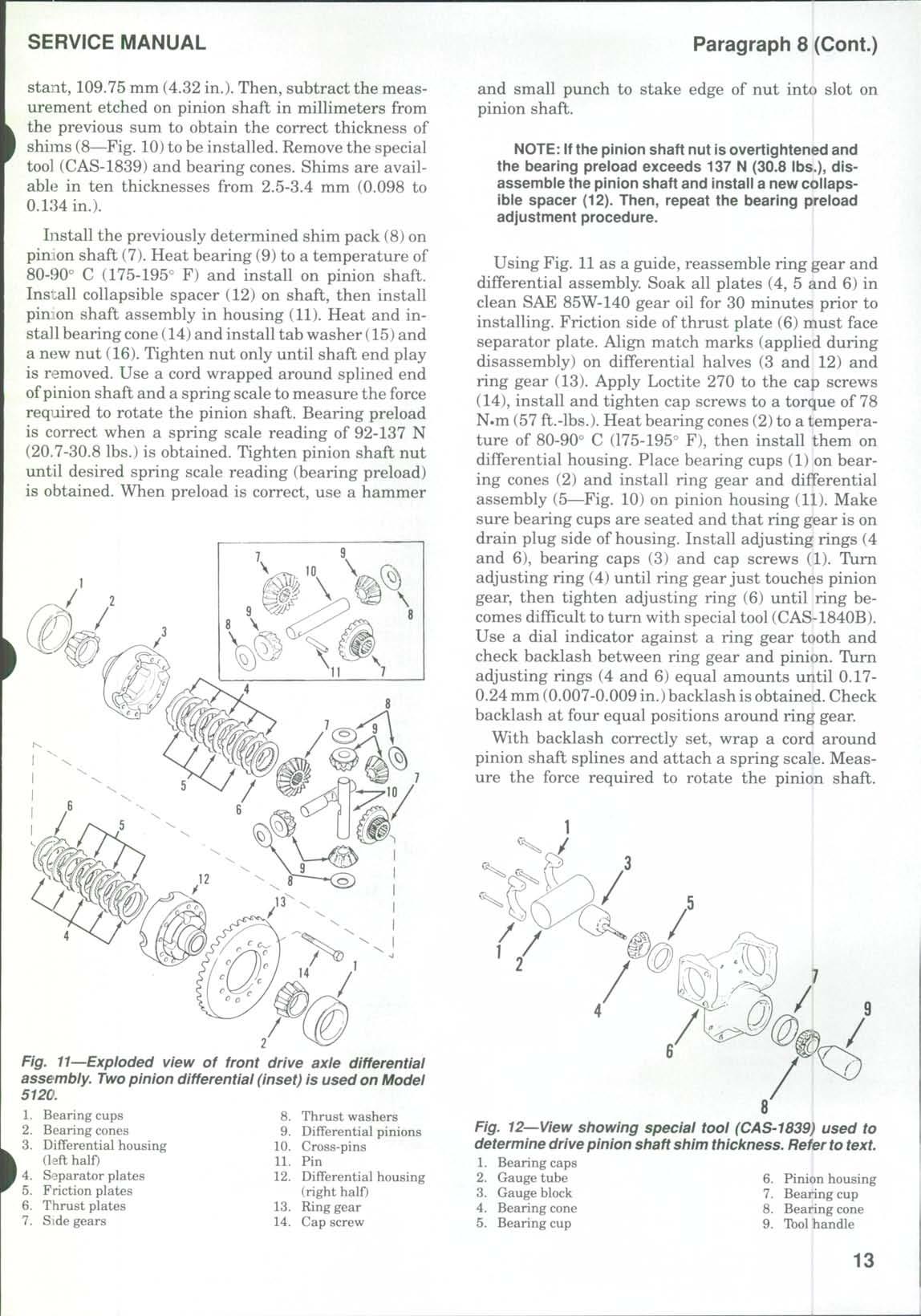
Using Fig. 11as a guide, reassemble ring gear and differential assembly. Soak all plates (4, 5 and 6) in clean SAE 85W-140 gear oil for 30 minutes prior to installing Friction side of thrust plate (6) must face separator plate. Align match marks (applied during disassembly) on differential halves (3 and 12) and ring gear (13) Apply Loctite 270 to the cap screws (14), install and tighten cap screws to a torque of 78 N-m (57 ft.-lbs.) Heat bearing cones (2)to a temperature of 80-90° C (175-195° F), then install them on differential housing. Place bearing cups (1) on bearing cones (2) and install ring gear and differential assembly (5—Fig 10) on pinion housing (11) Make sure bearing cups are seated and that ring gear is on drain plug side of housing. Install adjusting rings (4 and 6), bearing caps (3) and cap screws (1). Turn adjusting ring (4) until ring gear just touches pinion gear, then tighten adjusting ring (6) until ring becomes difficult to turn with special tool (CAS-1840B). Use a dial indicator against a ring gear tooth and check backlash between ring gear and pinion. Turn adjusting rings (4 and 6) equal amounts until 0.170.24 mm (0.007-0.009 in.)backlash isobtained Check backlash at four equal positions around ring gear.
With backlash correctly set, wrap a cord around pinion shaft splines and attach a spring scale. Measure the force required to rotate the pinion shaft.
Fig. 11-^Exploded view of front drive axle differential assembly. Two pinion differential (inset) is used on Model 5120.
Spring scale reading (bearing preload) should be3146 N (7-10 lbs.) above the pinion bearing preload of 92-137 N (20.7-30.8 lbs.) previously set Tighten both adjusting rings an equal amount to get the recommended preload Recheck backlash and readjust if necessary Tighten cap screws (1) to 266 N»m (196 ft.-lbs) torque Install locks (2) and secure with cap screws tightened to 10 N*m (7 ft.-lbs.) torque
Install thrust washer (18) and new "O" ring (19) over end of pinion shaft. Apply Loctite 515 to metal cover of new oil seal (17) and install seal until seated in pinion housing. Install front yoke (20) and snap ring (21).
When reinstalling the bevel gears and differential assembly, apply Loctite 515 to pinion housing mounting face and tighten retaining bolts to a torque of 120 N»m (88 ft.-lbs.) on axles equipped with bolts and washers or 169 N.m (125 ft.-lbs.) on axles equipped with self-locking bolts
Install steering cylinder (7—Fig.9)and bracket (8). Tighten retaining cap screws to a torque of 90 N.m
Oil drain rubber protector (66 ft.-lbs.). Install tie rod assemblies (4 and 9) and tighten into cylinder rod to a torque of 300 N.m (221 ft.-lbs.). Install the wheel hub, planetary, pivot housing and axle shaft assemblies (3) by reversing the removal procedures Tighten pivot pin cap screws to a torque of 137 N.m (101 ft.-lbs.) Connect tie rod (nds to steering arms and tighten nuts to 230 N.m < 170 ft.-lbs.) torque Reinstall drive axle assembly as outlined in paragraph 5 Fill axle housing with SAE 85W-140 gear oil to level plug opening Capacity is approximately 6.0 liters (6.3 U.S qt.) Use new "O" rings and reconnect steering lines The balance of reassembly is the reverse of disassembly.
FRONT DRIVE SHAFT
All Models So Equipped
9. R&R AND OVERHAUL. Toremove front drive shaft, block rear wheels securely Refer to Fig 13 and unbolt and remove shield (5) with engine oil d'-ain plug rubber protector (6) Unbolt "U"joints from front and rear yokes and remove drive shaft assembly Unbolt "U"joints from drive shaft Place mark on^^ear yoke (2)and transmission housing for aid in reassembly Pull rear yokefrom transmission Remove oil seal (1) from rear yoke If necessary, remove snap ring (21—Fig 10) and remove front yoke (20) Clean and inspect all parts for excessive wear or other damage and renew as necessary Install new oil seal and reassemble drive shaft assembly Reinstall by reversing removal procedure Tighten bolts in "U" joints to a torque of 39-44 N.m (29-32 ft.-lbs.) Install shield with engine oil drain plug rubber protectc-r
TIE RODS AND TOE-IN
All Models So Equipped
10. ADJUSTMENT. To check and adjust the toein, refer to Fig. 14 and measure distance "A" and
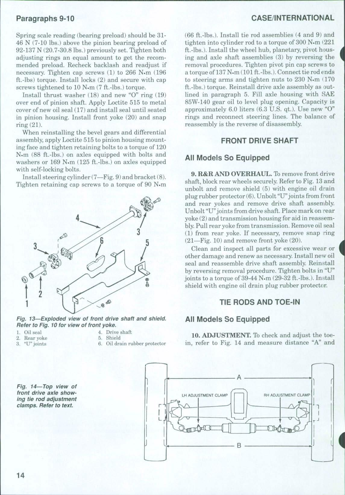
Fig. 14 Top view of front drive axle showing tie rod adjustment clamps. Refer to text.
Fig. 13 Exploded view of front drive shaft and shield. Refer to Fig. 10 for view of front yoke.
and bearing cone (3). Turn cap screw (10), drive gear (13) and pinion shaft (27) until idler gear (6) can be removed. See Fig. 16.Gear teeth will align in only one position for gear removal. Remove idler gear (6—Fig. 15) and bearing cone (9). Remove bearing cups (4 and 8) and snap rings (5 and 7) from idler gear Remove cap screw (10), spacer (11), shims (12) and drive gear (13) Remove park brake pin (33) Remove park brake housing cap screws (15 and 16) and install two long alignment studs (CAS-1995), then remove cap screw (14) Remove nut (17), washer (18) and cap screws (24) Carefully slide the clutch assembly and park brake assembly forward until clutch assembly can be removed Do not lose shims (20) If dowel (21) holds brake housing to clutch assembly (25), use extreme care when removing the units as an assembly. Lay the assembly on a bench and separate. Remove park brake components (28 through 32).
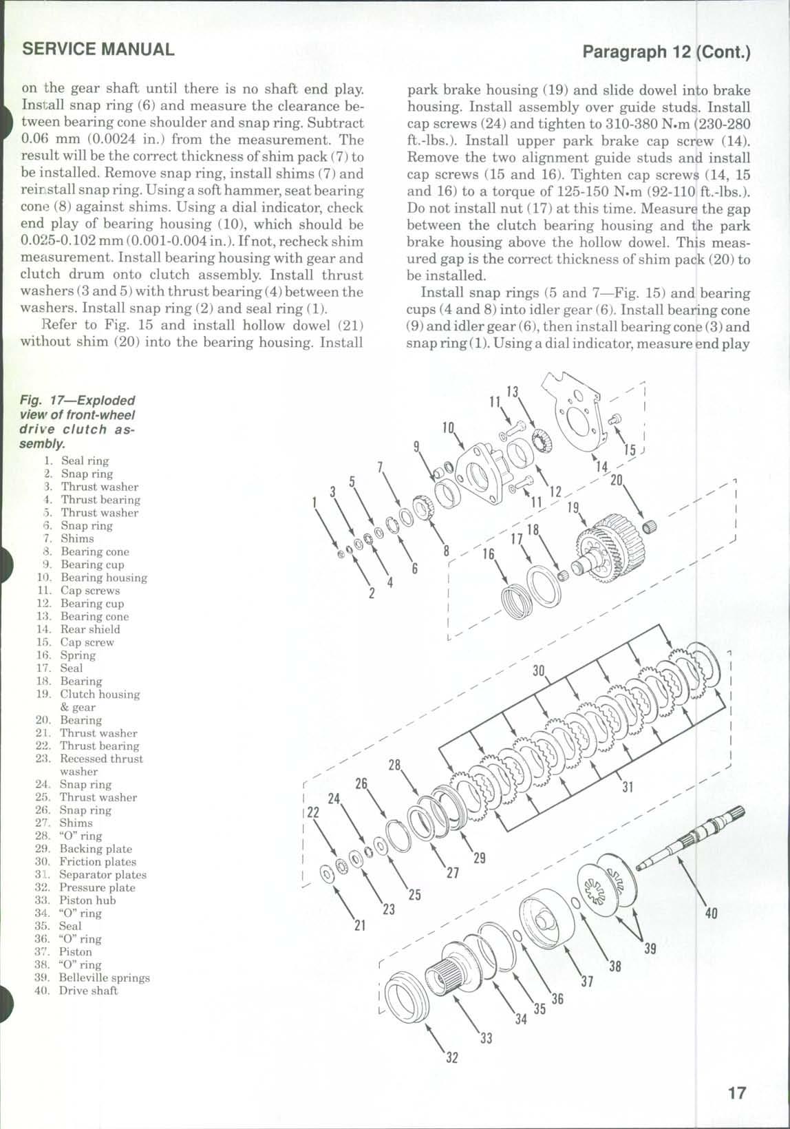
To disassemble the front-wheel drive clutch, use a sharp knife to cut and remove seal ring (1—Fig 17) Remove snap ring (2), thrust washers (3 and 5) and thrust bearing (4). Remove snap ring (6) and shims (7), then using a suitable press, remove gear and clutch housing (19) from bearing housing (10). Remove bearing cone (8) Remove seal (17), spring (16), cap screws (15), shield (14) and cap screws (11) Remove bearing cups (9 and 12) from bearing housing (10).Using a suitable puller, removebearing cone(13) from gear assembly (19). Remove bearings (18 and 20) Remove thrust washer (21), thrust bearing (22) and recessed thrust washer (23) Using a press (Fig 17A), compress Belleville springs (39—Fig. 17). Remove snap ring (24) and thrust washer (25), then release press and remove shaft (40) and Belleville washers (39) Remove and discard "O" rings (36 and 38)from shaft (40) Remove snap ring (26),shims (27)
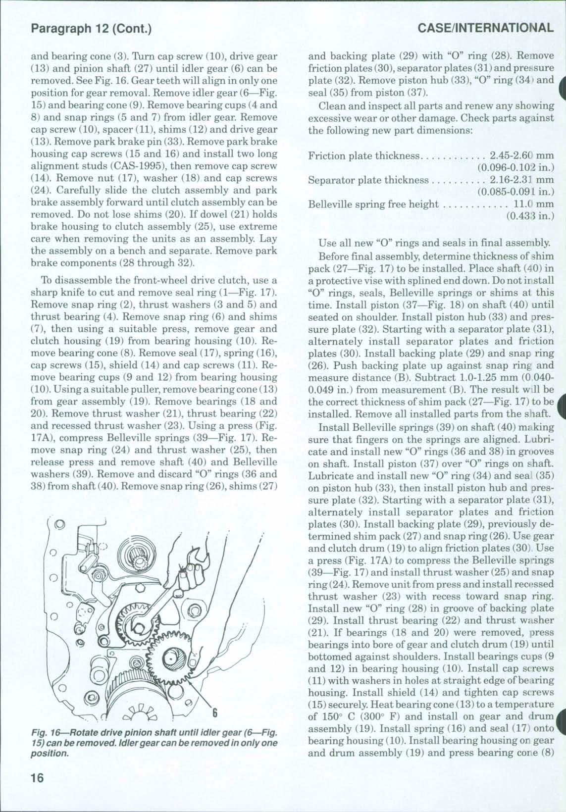
Fig. 16 Rotate drive pinion shaft until idler gear (6 Fig. 15) can be removed. Idlergear can be removed in only one position.
and backing plate (29) with "O" ring (28) Remove friction plates (30), separator plates (31)and pressure plate (32) Remove piston hub (33), "O" ring (341and seal (35) from piston (37)
Clean and inspect all parts and renew any showing excessive wear or other damage. Check parts against the following new part dimensions:
Friction plate thickness
Separator plate thickness
2.45-2.6(' mm (0.096-0.10:2 in.)
2.16-2.31 mm (0.085-0.09 Lin.)
Belleville spring free height ll.( mm (0.433 in.)
Use all new "O" rings and seals in final assembly. Before final assembly, determine thickness of shim pack (27—Fig 17) to be installed Place shaft (40) in a protective visewith splined end down. Donot ii stall "O" rings, seals, Belleville springs or shims at this time Install piston (37—Fig 18) on shaft (40) until seated on shoulder Install piston hub (33) and pressure plate (32) Starting with a separator plate (31), alternately install separator plates and friction plates (30). Install backing plate (29) and snap ring (26) Push backing plate up against snap ring and measure distance (B) Subtract 1.0-1.25 mm (0 0400.049 in.) from measurement (B) The result w.U be the correct thickness of shim pack (27—Fig. 17) to be i installed. Remove all installed parts from the shaft. Install Belleville springs (39) on shaft (40) making sure that fingers on the springs are aligned. Lubricate and install new "0" rings (36 and 38) in grooves on shaft Install piston (37) over "O" rings on shaft Lubricate and install new "O" ring (34) and sea (35) on piston hub (33), then install piston hub and pressure plate (32) Starting with a separator plate (31), alternately install separator plates and friction plates (30) Install backing plate (29), previously determined shim pack (27) and snap ring (26).Use gear and clutch drum (19) to align friction plates (30) Use a press (Fig 17A) to compress the Belleville spdngs (39—Fig 17)and install thrust washer (25) and snap ring (24) Removeunit from press and install recessed thrust washer (23) with recess toward snap ring. Install new "O" ring (28) in groove of backing plate (29) Install thrust bearing (22) and thrust washer (21) If bearings (18 and 20) were removed, press bearings into bore ofgear and clutch drum (19) until bottomed against shoulders. Install bearings cups (9 and 12) in bearing housing (10). Install cap screws (11)with washers in holes at straight edge of bearing housing Install shield (14) and tighten cap screws (15)securely. Heat bearing cone(13)to a temperature of 150° C (300° F) and install on gear and drumj assembly (19). Install spring (16) and seal (17) onto* bearing housing (10) Install bearing housing on gear and drum assembly (19) and press bearing core (8)
on the gear shaft until there is no shaft end play Install snap ring (6) andmeasure the clearancebetween bearing cone shoulder andsnap ring. Subtract 0.0() mm (0.0024 in.) from the measurement. The result will be thecorrect thickness ofshim pack (7) to be installed. Remove snap ring, install shims (7) and reir stall snap ring. Using a soft hammer, seat bearing cone (8)against shims. Using a dial indicator, check end play of bearing housing (10), which should be 0.025-0.102 mm (0.001-0.004 in.). Ifnot, recheck shim measurement Install bearing housing with gear and clutch drum onto clutch assembly Install thrust washers (3 and 5)with thrust bearing (4) between the washers Install snap ring (2)and seal ring (1)
to Fig 15 and install hollow dowel (21) without shim (20) into the bearing housing Install
U^Exploded view of front-wheel drive clutch assembly.
park brake housing (19) and slide dowel into brake housing Install assembly over guide studs Install cap screws (24) andtighten to 310-380 N.m (230-280 ft.-lbs.) Install upper park brake cap screw (14) Remove the two alignment guide studs and install cap screws (15and 16).Tighten cap screws (14, 15 and 16)to a torque of 125-150 N.m (92-110 ft.-lbs.). Do notinstall nut (17) at this time. Measure the gap between the clutch bearing housing and the park brake housing above the hollow dowel. This measured gap isthe correct thickness ofshim pack (20) to be installed.
Install snap rings (5 and 7—Fig. 15) and bearing cups (4 and8) into idler gear (6). Install bearing cone (9)and idler gear (6), then install bearing cone (3) and snap ring(l). Using adial indicator, measure end play
of idler gear Subtract 0.06 mm (0.0024 in.) from this measurement to obtain correct thickness of shim pack (2) to be installed This will provide idler gear end play of 0.025-0.102 mm (0.001-0.004 in.)
Remove snap ring (1—Fig 15), bearing cone (3), idler gear (6) and bearing cone (9) Lay aside with the determined shim pack (2) Remove cap screws (15 and 16) and reinstall the long alignment studs Remove upper mounting cap screw (14) Remove cap screws (24) and carefully remove the clutch and park brake housing. Separate the assemblies and install the predetermined shim pack (20) over the dowel (21), then slide assemblies back together over the dowel. Install brake hub (28) onto drive pinion shaft (27) with recessed end to the rear. Install backing plate (29), friction plate (30), actuator (31) and second friction plate (32) Reinstall park brake and clutch assembly Install and tighten clutch mounting cap screws (24) and nut (17) with washer (18) to a torque of 310-380 N.m (230-280 ft.-lbs.) Install cap screw (14), remove alignment guide studs and install cap screws (15 and 16) Tighten cap screws to 125-150 N.m (92-110 ft.-lbs.) torque. Connect park brake linkage. Install drive gear (13) with long side of hub forward. Install pinion shaft cap screw (10), spacer (11) and shims (12) and tighten cap screw to a torque of335-375 N.m (247-277 ft.-lbs.). Install bearing cone
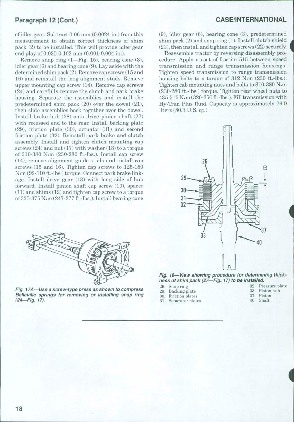
17A—Use a screw-type press as shown to compress Belleville springs for removing or installing snap ring (24—Fig. 17).
(9), idler gear (6), bearing cone (3), predetermined shim pack (2) and snap ring (1) Install clutch shield (23),then install and tighten cap screws (22)securely Reassemble tractor by reversing disassembly procedure Apply a coat of Loctite 515 between speed transmission and range transmission housings Tighten speed transmission to range transmission housing bolts to a torque of 312 N.m (230 ft.-lbs.). Tighten cab mounting nuts and bolts to 310-380 N.m (230-280 ft.-lbs.) torque. Tighten rear wheel nuts to 435-515N.m (320-350 ft.-lbs.). Fill transmission with Hy-Tran Plus fiuid. Capacity is approximately 76.0 liters (80.3 U.S. qt.).
Fig. 18 View showing procedure for determining thickness of shim pack (27^Fig. 17) to be installed.
26 Snap ring
29 Backing plate
30 Friction plates
31 Separator plates
32 Pressure plate
33 Piston hib
37 Piston
40 Shaft
Fig.
POWER STEERING SYSTEM
Ml models are equipped with hydrostatic power steering using a Danfoss steering unit. The variable displacement piston-type pump fuinishes pressurized oil to the compensator valve where a portion of the oil is diverted to the steering unit at a pressure of 16,893-17,582 kPa (2450-2550 psi). One double-acting steering cylinder is used on all models.
FLUID, FILTER AND BLEEDING
All Models
13. The transmission and hydraulic system fluid is used in the power steering system Adipstick, located at the right rear ofthe tractor rear housing, indicates fluid level Use Hy-Tran Plus fluid in all models Refer to CONDENSED SERVICE DATA for reservoir capacity and to HYDRAULIC SYSTEM SECTION for adcitional hydraulic system information An externally mounted, screw-on-type pressure filter is located onthe right side ofspeed transmission housing. The manufacturer recommends that transmission anc hydraulic fluid be drained and new Hy-Tran Plus fluid beinstalled after each 1000 hours of operation. Filter element (14—Fig 19)should be changed whenever service monitor on instrument cluster indicates a clogged filter or at least once each 1000 hours of operation
To change the filter element (14), use a strap wrench and rotate element counterclockwise toremove Lubricate gasket (13) on new element with clean oil and install element on adapter (12) until gasket contacts filter manifold. Then, hand tighten element an additional one-third turn.
Start engine and check for leaks. To bleed the steering system, operate engine at low idle speed and rotfite steering wheel from lock to lock several times until steering action is firm. Check transmission oil level andadd Hy-Tran Plus oilas necessary
TROUBLESHOOTING
All Models
14. Some troubles that may occur in the operation of the power steering system and their possible causes areas follows:
1. Nopower steering or steers slowly.
a Binding mechanical linkage
b. Excessive load on front wheels and/or air pressure low in front tires
c. Steering cylinder piston seal faulty or cylinder damaged.
d Faulty hand pump |
e. Faulty hydraulic supply pump.
f. Faulty priority valve in compensator valve assembly.
2 Will notsteer manually.
a Binding mechanical linkage
b Excessive load on front wheels and/or air pressure low in front tires
c Pumping element in hand pump faulty
d Faulty seal insteering cylinder or cylinder damaged.
3. Hard steering through complete cycle.
a. Low pressure from supply pump.
b Internal or external leakage
c. Faulty steering cylinder.
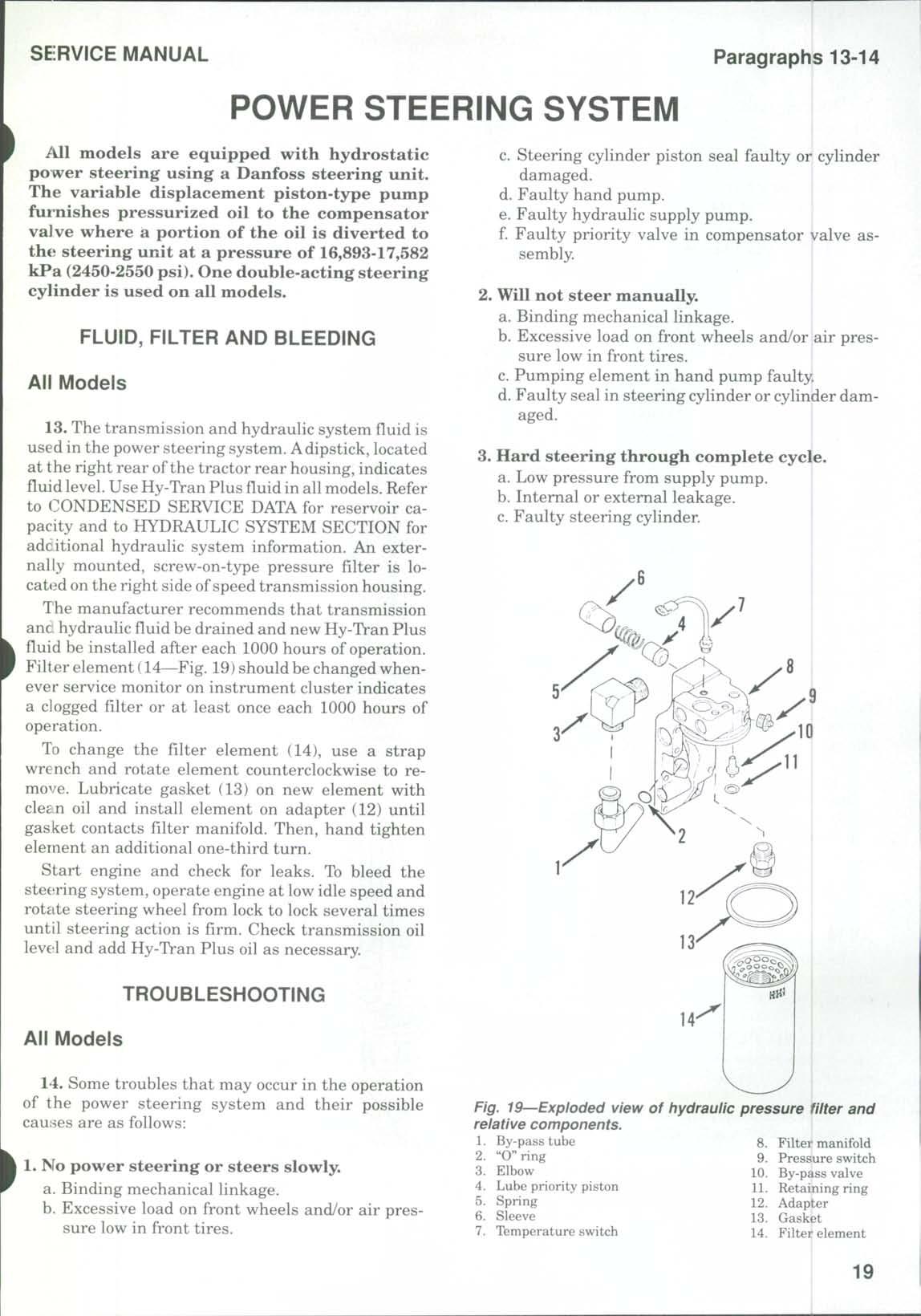
Fig. 19—Exploded view of hydraulic pressure filter and relative components.
d Binding mechanical linkage
e Excessive load on front wheels and/or air pressure low in front tires
4. Momentary hard or lumpy steering.
a. Air in power steering circuit.
STEERING OPERATING PRESSURE
All Models
15 To check the power steering operating pressure, refer to Fig. 20 and remove plug (5). Install a 30,000 kPa (4000 psi) pressure gauge. Operate tractor until the hydraulic oil reaches a temperature of49°C (120° F) Operate engine at 1500 rpm, then turn and hold steering on full lock. Check pressure gauge reading, which should be 16,893-17,582 kPa (2450-2550 psi). If pressure is not correct, remove cap from relief valve (3), loosen locknut and turn adjusting screw as required to obtain correct pressure If pressure is too low and turning adjusting screw clockwise will not increase pressure, remove test gauge and install plug (5) Refer to Fig 21 and remove plug (P) from pump compensator (PC) Install the 30,000 kPa (4000 psi) pressure gauge. Operate engine at 1500 rpm and operate remote valve levers for maximum pressure. Pressure should be 18,600-19,300 kPa (2700-2800 psi) If not, remove cap from relief valve (4—Fig 20), loosen locknut and turn adjusting screw to obtain correct pressure. Tighten locknut and install cap. Remove gauge and install plug. Recheck steering pressure as previously outlined and adjust as necessary
NOTE: If the main remote/hitch pressure is too low (below steering pressure), adjusting the steering pressure relief valve wiii not increase steering pressure.
OPERATIONAL TESTS
All Models
The following tests are valid only if the power steering system is void ofany air. If necessary, bleed system as outlined in paragraph 13 before performing tests.
16. HAND PUMP. With power steering supply pump inoperative (engine not running), attempt to steer manually in both directions.
NOTE: Manual steering with power steering supply pump inoperative, will require high steering effort
If manual steering can be accomplished with supply pump inoperative, it can be assumed that the manual steering pump is operating satisfactorily.
17. STEERING WHEEL SLIP (CIRCUIT TEST). Steering wheel slip is the term used to describe the inability of the steering wheel to hold a given position without further steering movement.
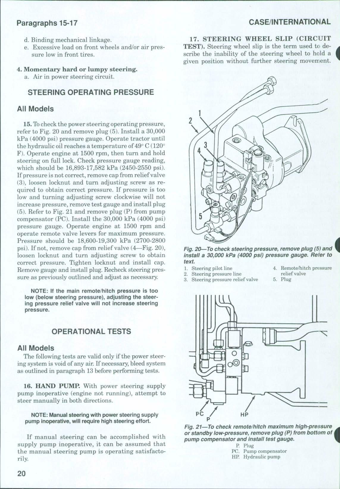
Fig. 20—To check steering pressure, remove plug (5) and install a 30,000 kPa (4000 psi) pressure gauge. Refer to text.
1 Steering pilot line
4 Remote/hitch pn ssure
2 Steering pressure line relief valve
3 Steering pressure relief valve 5 Plug
Fig. 21—To check remote/hitch maximum high-pressure or standby low-pressure, remove plug (P) from bottom of j pump compensator and install test gauge, P Plug
PC. Pump compensator
HP Hydraulic pump
SERVICE MANUAL
Wtieel slip is generally due to leakage, either internal or external, or a faulty hand pump or steering cylindei. Some steering wheel slip, with hydraulic fluid at operating temperature, is normal and permissible A maximum ofone revolution per minute is acceptable
To check for steering wheel slip, proceed as follows: Operate tractor at 1500 rpm until hydraulic fluid is warmed to a temperature of 49° C (120° F) Remove steering wheel cap, then turn front wheels until they are against the stop Attach a torque wrench to steering wheel nut Apply 8 N.m (72 in.-lbs.) of force to steering shaft in same direction as front wheels are positioned against stop, then count number of revolutions of steering wheel in a period of one minute Use same procedure and check steering wheel slip in opposite direction Up to one revolution in one minute in either direction is acceptable and system can be considered as operating satisfactorily. If steering wheel revolutions per minute exceed the maximum, record total rpm for use in checking steering cylinder ortLandpump as outlined in the following paragraph.
18. STEERING CYLINDER TEST. If steering wh(iel slip, as checked in paragraph 17, exceeds the maximum one revolution per minute, proceed as follows: Disconnect and plug lines to steering cylinder. Make sure that fluid is at operating temperature, then repeat steering wheel slip test as outlined in paragraph 17 If steering wheel slip is less than that ' recorded in previous test, overhaul or renew steering cyliader. If steering wheel slip,with steering cylinder disconnected, still exceeds maximum one revolution per minute, overhaul or renew steering hand pump
HYDRAULIC SUPPLY PUMP
All
Models
19. The power source for the hydrostatic steering system is the variable displacement axial piston, 78.5 L/m (20.7 U.S. gpm) pump. This pump also furnishes pressurized oil for the main hydraulic system. Refer to EYDRAULIC SYSTEM SECTION for information and service procedures for the pump.
STEERING CONTROL UNIT (HAND PUMP)
All Models
20. REMOVE AND REINSTALL. To remove the hand pump assembly, first disconnect battery cables, then drive roll pin from throttle pedal. Remove cab floor cover Remove steering column side covers and steering tilt control lever Remove screws and steering column center panel Identify and disconnect the four steering tubes and the signal port tube from the
hand pump Plug or cap all openings immediately to prevent dirt from entering the system Remove right side steering pivot bolt. Unbolt and remove right mounting bracket. Remove roll pin from the coupling. Remove remaining two bolts and lift out hand pump assembly.
To reinstall the hand pump assembly, place pump in position and install (but donot tighten) the two left mounting bolts. Align holes in input shaft and "U" joint and install roll pin. Install steering column right mountingbracket. Install right side hand pump bolts, then tighten all four mounting bolts. Install and tighten steering column pivot bolt to a torque of32-37 N.m (23-27 ft.-lbs.). Reconnect steering lines and
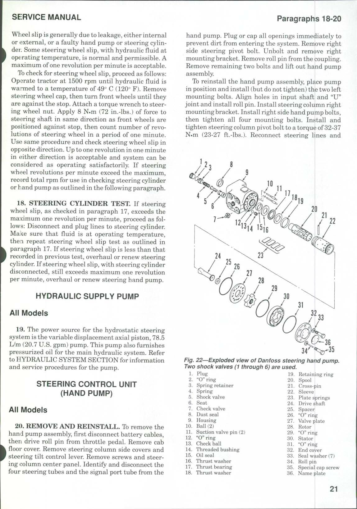
Steering hand pump, used.
19 Retaining ring
Spool
Cross-pin 22. Sleeve
Plate springs 24. Drive shaft
Spacer 26 "O"ring 27 Valve plate
28 Rotor 29 "O"ring
Stator
"O" ring
End cover 33 Seal washer (7) 34 Roll pin
35 Special cap screw 36 Name plate
Fig. 22—Exploded view of Danfoss
SERVICE MANUAL
"0" rings with petroleum jelly during reassembly. Wtien installing plate springs (23—Fig. 22), first install the twoflat springs. Then, install the two curved springs (arches back-to-back) in between the two flat springs. When installing rotor (28) on shaft (24), make certain that cross-pin in shaft aligns with center ofvalleys in rotor See Fig 25 Align match marks and tighten end cover cap screws (35) to a torque of 30-35 N.m (22-26 ft.-lbs.)
Iastall input steering shaft and mounting bracket, and tighten cap screws securely.
STEERING CYLINDER
Models With Two-Wheel Drive
22. R&R AND OVERHAUL. To remove the steering cyhnder, loosenjam nut (22—Fig. 26). Disconnect steering lines from cylinder and cap or plug all openings. Disconnect ball joint (23) from steering arm, then remove balljoint from steering cylinder. Remove nut (1) and lift out steering cylinder.
To disassemble the steering cylinder, remove snap ring (21), push seal gland (17) inward and remove retaining ring (20) Grasp end ofcylinder rod (11) and pull outward to remove gland assembly (15 through 19) and the piston rod assembly (11 through 14) Remove wiper ring (19), seal ring (18), backup ring

Fig. 27—Exploded view of steering cylinder used on tractors equipped with front drive axle.
Nut
Tie rod end (L.H.)
Clamp
Tie rod stud (L.H.)
Wiper seal
Backup washer
Rod seal
End cap
Backup ring
"O"ring
Piston rod
12 Wear ring
13 Piston seal ring
14 Wear ring
15. Cylinder tube 16 Rod seal 17 Backup ring
18 Wiper seal
19 Tie rod stud (R.H.)
20 Clamp
21 Tie rod end (R.H.) 22 Nut
Fig. 26 Exploded view of steering cylinder used on twowheel-drive tractors.
(16) and "O" ring (15) from gland (17) Remove seal ring (13) and wear rings (12 and 14) from piston rod Remove cylinder end (3)from cylinder tube (4). Using special tool (CAS-3461) and a long extension inside the cylinder tube, rotate seal gland (8) until retaining wire (7) is removed through slot in cylinder tube. Remove the gland assembly. Remove backup ring (5), seal ring (6), backup ring (9) and "O" ring (10) from gland (8).
Clean and inspect seal glands (8and 17),piston rod (11) and cylinder tube (4)for scoring or other damage and renew as necessary. A seal kit including all "O" rings, seals and retaining rings is available.
When reassembling, lubricate all internal parts with clean Hy-Tran Plus oil and reverse the disassembly procedure. Apply Loctite R.T.V. sealant 595 to the seal gland retaining wire slot. Apply Loctite 270 to the threads of cylinder end (3) and tighten to a torque of 400 N.m (295 ft.-lbs.).
When reinstalling cylinder assembly, tighten nut (1) to a torque of 380-420 N.m (280-310 ft.-lbs.) Tighten jam nut (22) to 200 N.m (148 ft.-lbs.) Connect balljoint (23) to steering arm and tighten to 400 N-m (295 ft.-lbs.) Reconnect steering lines and bleed air from steering system
Models With Front Drive Axle
23. R&R AND OVERHAUL. To remove the steering cylinder, first raise front of tractor, support with two axle stands and remove front wheels Remove

nuts (1 and 22—Fig 27) and disconnect tie rod ends (2 and 21) from steering arms Remove tie rod studs (4 and 19) from ends of piston rod (11) Disconnect steering lines at cylinder Remove elbow fitting from right end ofcylinder Unbolt and remove cylinder out left side of drive pinion housing
To disassemble the steering cylinder, remove end cap (8) and piston rod (11) Remove wiper seal '5), backup ring (6), rod seal (7), backup ring (9) and 'O" ring (10) from end cap (8), and piston seal ring (13) and wear rings (12 and 14) from piston rod (11). Remove wiper seal (18),backup ring (17) and rod seal (16) from right end of cylinder tube (15).
Clean and inspect end cap (8), piston rod (11) and cylinder tube (15) for excessive wear or scoring and renew as necessary Aseal kit, consisting of"O"rings, wear rings seal rings, backup rings and wiper seals, is available When reassembling, lubricate all internal parts with clean Hy-Tran Plus oil
Reinstall cylinder by reversing the removal prctcedures Tighten steering cylinder mounting bolts to a torque of90 N.m (66 ft.-lbs.) Tighten tie rod stud.s (4 and 19) into ends of piston rod (11) to a torque of.'100 N.m (221 ft.-lbs.) Connect tie rod ends (2 and 21' to steering arms and tighten nuts (1and 22) to 230 r^-.m (170 ft.-lbs.) Use new "O" rings and connect steering lines. Install front wheels and tighten nuts to MOO N.m (221 ft.-lbs.) torque. Adjust toe-in as outlined in paragraph 10. Bleed air from steering system by operating engine at low idle speed and turn steering wheel lock-to-lock several times.
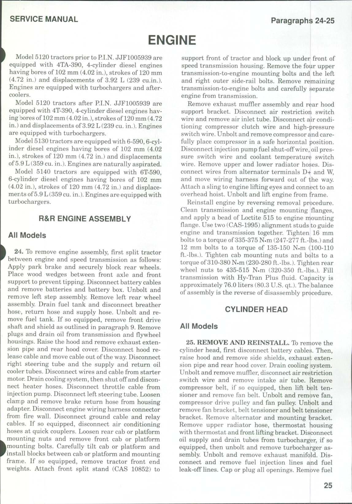
ENGINE
]V[odel 5120 tractors prior to RI.N. JJF1005939 are equipped with 4TA-390, 4-cylinder diesel engines having bores of 102 mm (4.02 in.), strokes of 120 mm (4.72 in.) and displacements of 3.92 L (239 cu.in.) Eng:ines are equipped with turbochargers and aftercoolers.
Model 5120 tractors after PI.N JJF1005939 are equipped with 4T-390, 4-cylinder diesel engines having bores of 102 mm (4.02 in.), strokes of 120 mm (4.72 in.) and displacements of3.92 L (239 cu in.) Engines are equipped with turbochargers
W^odel5130 tractors are equipped with 6-590,6-cylinder diesel engines having bores of 102 mm (4.02 in.), strokes of 120 mm (4.72 in.) and displacements of5.9 L(359 cu in.) Engines are naturally aspirated
IVlodel 5140 tractors are equipped with 6T-590, 6-cylinder diesel engines having bores of 102 mm (4.02 in.), strokes of 120 mm (4.72 in.) and displacements of5.9 L(359cu in.) Engines are equipped with turbochargers
R&R ENGINE ASSEMBLY
All Models
24 To remove engine assembly, first split tractor betv/een engine and speed transmission as follows: Apply park brake and securely block rear wheels. Place wood wedges between front axle and front sup})ort to prevent tipping. Disconnect battery cables and remove batteries and battery box Unbolt and remove left step assembly Remove left rear wheel assembly. Drain fuel tank and disconnect breather hose-, return hose and supply hose. Unbolt and remove fuel tank If so equipped, remove front drive shaft and shield as outlined in paragraph 9 Remove plugs and drain oil from transmission and fl3^wheel housings. Raise the hood and remove exhaust extension pipe and rear hood cover. Disconnect hood release cable and move cable out ofthe way Disconnect right steering tube and the supply and return oil cooler tubes Disconnect wires and cable from starter motor. Drain cooling system, then shut off and disconnect heater hoses. Disconnect throttle cable from injection pump Disconnect left steering tube Loosen clarfLp and remove brake return hose from housing adapter. Disconnect engine wiring harness connector from fire wall. Disconnect ground cable and relay cables. If so equipped, disconnect air conditioning hoses at quick couplers Loosen rear cab or platform mounting nuts and remove front cab or platform Amounting bolts. Carefully tilt cab or platform and 'install blocks between cab or platform and mounting frame If so equipped, remove tractor front end weights Attach front split stand (CAS 10852) to
support front of tractor and block up under front of speed transmission housing. Remove the four upper transmission-to-engine mounting bolts and the left and right outer side-rail bolts Remove remaining transmission-to-engine bolts and carefully separate engine from transmission
Remove exhaust muffler assembly and rear hood support bracket. Disconnect air restriction switch wire and remove air inlet tube. Disconnect air conditioning compressor clutch wire and high-pressure switch wire.Unbolt and remove compressor and carefully place compressor in a safe horizontal position. Disconnect injection pump fuel shut-off wire, oil pressure switch wire and coolant temperature switch wire Remove upper and lower radiator hoses Disconnect wires from alternator terminals D+ and W, and move wiring harness forward out of the way Attach a sling to engine lifting eyes and connect to an overhead hoist Unbolt and lift engine from frame
Reinstall engine by reversing removal procedure Clean transmission and engine mounting flanges, and apply a bead of Loctite 515 to engine mounting flange. Use two (CAS-1995) alignment studs to guide engine and transmission together Tighten 16 mm bolts to a torque of335-375 N.m (247-277 ft.-lbs.) and 12 mm bolts to a torque of 135-150 N.m (100-110 ft.-lbs.). Tighten cab mounting nuts and bolts to a torque of310-380 N.m (230-280 ft.-lbs.). Tighten rear wheel nuts to 435-515 N.m (320-350 ft.-lbs.) Fill transmission with Hy-Tran Plus fluid Capacity is approximately 76.0 liters (80.3 U.S qt.) The balance of assembly is the reverse of disassembly procedure.
CYLINDER HEAD
All Models
25. REMOVE AND REINSTALL. To remove the cylinder head, first disconnect battery cables Then, raise hood and remove side shields, exhaust extension pipe and rear hood cover. Drain cooling system. Unbolt and remove muffler, disconnect air restriction switch wire and remove intake air tube. Remove compressor belt, if so equipped, then lift belt tensioner and remove fan belt Unbolt and remove fan, compressor drive pulley and fan pulley. Unbolt and remove fan bracket, belt tensioner and belt tensioner bracket Remove alternator and mounting bracket Remove upper radiator hose, thermostat housing with thermostat and front lifting bracket Disconnect oil supply and drain tubes from turbocharger, if so equipped, then unbolt and remove turbocharger assembly Unbolt and remove exhaust manifold Disconnect and remove fuel injection lines and fuel leak-ofT lines Cap or plug all openings Remove fuel
Thermostat housing bolts
Exhaust manifold bolts
Beit tensioner bracket bolts
Belt tensioner bolt
Fan pulley bracket bolts
Fan retaining bolts
Vaive cover bolts
24N.m (18 ft.-lbs.)
43 N.m (32 ft.-lbs.)
24 N.m (18 ft.-lbs.)
43 N.m (32 ft.-lbs.)
24 N.m (18 ft.-lbs.)
43 N-m (32 ft.-lbs.)
24 N-m (18 ft.-lbs.)
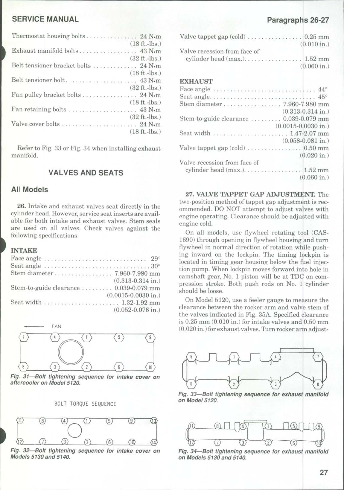
Refer to Fig 33or Fig 34 when instalHng exhaust manifold.
VALVES AND SEATS
All Models
26. Intake and exhaust valves seat directly in the cyl Lnderhead. However, service seat inserts are available for both intake and exhaust valves Stem seals are used on all valves Check valves against the following specifications:
INTAKE
Face angle
Seat angle
Stem diameter
Stem-to-guide clearance
Seat width
29°
30°
7.960-7.980 mm
(0.313-0.314 in.)
0.039-0.079 mm
(0.0015-0.0030 in.)
1.32-1.92 mm
(0.052-0.076 in.)
Valve tappet gap (cold)
Valve recession from face of cylinder head (max.)
EXHAUST
Face
Stem-to-guide clearance
0.25 mm (0.010in.)
mm (0.060in.)
j
7.960-7.980 mm
(0.313-0.314 in.)
0.039-0.079 mm
(0.0015-0.0030 in.)
Seat width 1.47-2.07 mm
(0.058-0.081in.)
Valve tappet gap (cold) 0.50 mm (0.020 in.)
Valve recession from face of | cylinder head (max.).
mm (0.060 in.)
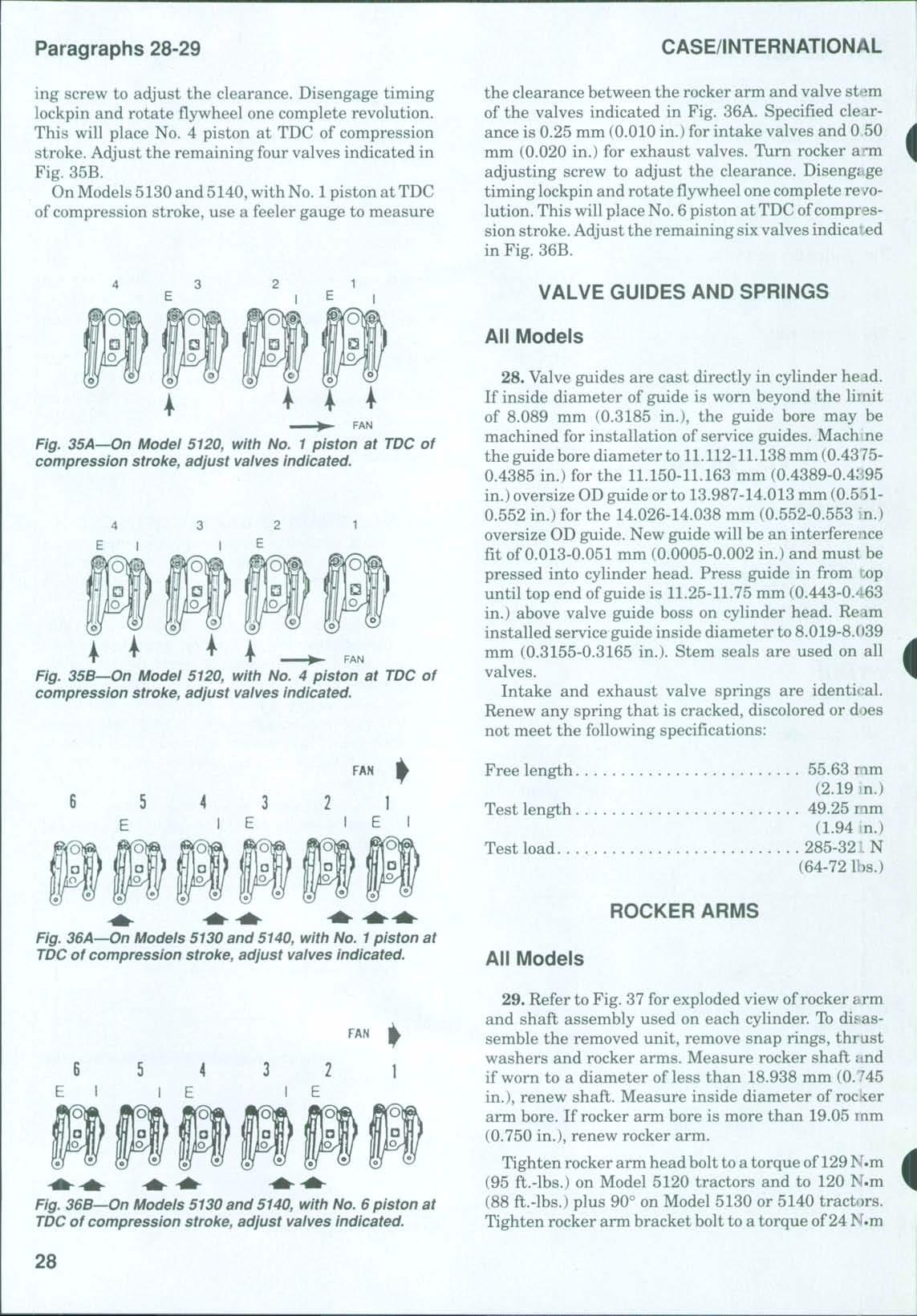
27. VALVE TAPPET GAP ADJUSTMENT. The two-position method oftappet gap adjustment is recommended DO NOT attempt to adjust valves with engine operating Clearance should be adjusted with engine cold.
On all models, use flywheel rotating tool (CAS1690) through opening in flywheel housing and turn flywheel in normal direction of rotation while pushing inward on the lockpin. The timing lockpin is located in timing gear housing below the fuel injection pump. When lockpin moves forward into hole in camshaft gear No 1 piston will be at TDC on compression stroke Both push rods on No 1 cylinder should beloose.
On Model 5120, use a feeler gauge to measure the clearance between the rocker arm and valve stem of the valves indicated in Fig 35A Specified clearance is 0.25 mm(0.010 in.) for intake valves and 0.50 mm (0.020in.)for exhaust valves Turn rocker arm adjust-
Fig. 31—Bolt tightening sequence for intake cover on aftercooler on Model 5120.
BOLT TORQUE SEQUENCE
Fig. 33—Bolt tightening sequence for exhaust manifold on Model 5120.
Fig. 32—Bolt tightening sequence for intake cover on Models 5130 and 5140.
Fig. 34—Bolt tightening sequence for exhaust manifold on Models 5130 and 5140.
ing screw to adjust the clearance. Disengage timing lockpin and rotate flywheel one complete revolution. This will place No. 4 piston at TDC of compression stroke. Adjust the remaining four valves indicated in Fig. 35B.
On Models 5130 and 5140,with No. 1 piston at TDC of compression stroke, use a feeler gauge to measure
the clearance between the rocker arm and valve sttim of the valves indicated in Fig. 36A. Specified clearance is 0.25 mm (0.010 in.) for intake valves and 0 50 mm (0.020 in.) for exhaust valves. Turn rocker a^m adjusting screw to adjust the clearance. Disengage timing lockpin and rotate flywheel one complete revolution This will place No 6 piston at TDCofcompression stroke Adjust the remaining sixvalves indicai-ed in Fig 36B
VALVE GUIDES AND SPRINGS
All Models
Fig, 35A—On Model 5120, with No. 1 piston at TDC of compression stroke, adjust valves indicated.
FAN
Fig. 35B—On Modei 5120, with No. 4 piston at TDC of compression stroke, adjust valves indicated.
28. Valve guides are cast directly in cylinder head. If inside diameter of guide is worn beyond the limit of 8.089 mm (0.3185 in.), the guide bore may be machined for installation of service guides. Mach ne the guide bore diameter to 11.112-11.138mm(0.43750.4385 in.) for the 11.150-11.163 mm (0.4389-0.4:;95 in.)oversize ODguide orto 13.987-14.013 mm (0.5510.552 in.) for the 14.026-14.038 mm (0.552-0.553 in.) oversize OD guide. New guide will be an interference fit of 0.013-0.051 mm (0.0005-0.002 in.) and must be pressed into cylinder head Press guide in from nop until top end ofguide is 11.25-11.75 mm (0.443-0.463 in.) above valve guide boss on cylinder head Re am installed service guide inside diameter to 8.019-8.(i39 mm (0.3155-0.3165 in.). Stem seals are used on all valves
Intake and exhaust valve springs are identical Renew any spring that is cracked, discolored or does not meet the following specifications:
Free
Test
55.63 mm (2.19 in.)
49.25 mm (1.94 in.)
Test load 285-32:. N (64-72 lbs.)
ROCKER ARMS
Fig. 36A—On Models 5130 and 5140, with No. 1 piston at TDC of compression stroke, adjust valves indicated. All Models
29. Refer to Fig. 37for exploded view ofrocker arm and shaft assembly used on each cylinder. To disassemble the removed unit, remove snap rings, thrust washers and rocker arms Measure rocker shaft iind if worn to a diameter of less than 18.938 mm (0.^45 in.), renew shaft. Measure inside diameter of rocker arm bore If rocker arm bore is more than 19.05 mm (0.750 in.), renew rocker arm
Fig. 36B—On Models 5130 and 5140, with No. 6 piston at TDC of compression stroke, adjust valves indicated.
Tighten rocker arm head bolt to atorque of 129N.m (95 ft.-lbs.) on Model 5120 tractors and to 120 N.m (88 ft.-lbs.) plus 90° on Model 5130 or 5140 tractors Tighten rocker arm bracket bolt to a torque of24 N.m
FAN
FAN
(18 ft.-lbs.) on all models Adjust valve tappet gap as OLitlined in paragraph 27 Tighten rocker cover bolts to 24 N.m (18 ft.-lbs.)
CAM FOLLOWERS
All Models
30 The mushroom-type cam followers can be removed from below after first removing camshaft, oil pan and engine balancer if so equipped, as outlined in paragraphs 36, 51 and 48
Measure outside diameter of cam follower stem Renew cam followers if outside diameter of stems is less than 15.960 mm (0.628 in.) Measure inside diameter ofcam follower bores in cylinder block Maxi-
mum bore diameter is 16.055 mm (0.632 in.) If bores exceed the limit, renew cylinder block
TIMING GEAR COVER
All Models
31 To remove the timing gear cover (11—Fig 38), disconnect battery cables and remove hood, grille and side panels If so equipped, unbolt air conditioning condenser and receiver-drier and lay rearward on engine It is not necessary to disconnect the air conditioner lines Disconnect air filter restriction switch and remove air intake tube Identify and disconnect oil cooler hoses Remove front weights, if so equipped Drain coolant and remove upper and lower radiator hoses. Disconnect steering cylinder lines and, if so equipped, unbolt and remove front-wheel drive shaft and shield. Attach split stand to side rails and attach a hoist to front support. Unbolt and separate front axle and front support from tractor. If so equipped, loosen compressor bolts and remove drive belt. Raise fan belt tensioner and remove fan belt. Unbolt and remove fan, compressor drive pulley and fan pulley Unbolt and remove crankshaft pulley Then, unbolt and remove timing gear cover
NOTE: Refer to paragraph 45 for front crankshaft oilseal installation andtiming gear cover aiignment.

Fig. 37^Expioded view of rocker arm assembly used on e&ch cylinder.
Fig. 38 Exploded view of timing gear housing, cover and reiated parts.
When reassembling, use new cover gasket and tighten cover retaining cap screws to a torque of 24 N.m (18 ft.-lbs.) Tighten crankshaft pulley bolts to a torque of 130-144 N.m (96-106 ft.-lbs.) Tighten fan retaining bolts to 43 N.m (32 ft.-lbs.) Tighten side rails to front support bolts to 134-151 N.m (100-110 ft.-lbs.) and tighten engine to frame bolts to a torque of 335-375 N.m (247-277 ft.-lbs.)
TIMING GEARS
All Models
The timing gear train consists of the crankshaft gear, camshaft gear and injection pump drive gear Engine oil pump is mounted on front of engine block inside the timing gear housing and drives through an idler gear from crankshaft gear, becoming part of the gear train Refer to the appropriate following paragraphs for timing, inspection and overhaul information
32. TIMING MARKS. When installing camshaft gear and crankshaft gear, align single punch mark on crankshaft gear with double punch mark on camshaft gear (Fig. 39). When installing injection pump drive gear, align the correct letter on injection pump gear (Fig 40) with the single punch mark on camshaft
CLICK HERE TO DOWNLOAD THE COMPLETE MANUAL
• Thank you very much for reading the preview of the manual.
• You can download the complete manual from: www.heydownloads.com by clicking the link below
• Please note: If there is no response to CLICKING the link, please download this PDF first and then click on it.
CLICK HERE TO DOWNLOAD THE