DOWNLOAD PDF Pages 001 0170 Massey Ferguson MF 6400 Tractor Repair & Parts Manual
01- Introduction - Specifications
CONTENTS
1A10-Using the manual
1B10-SPECIFICATIONS- General specifications
1B11-SPECIFICATIONS- Ground speeds
1B12-SPECIFICATIONS- Dimensions
1B13-SPECIFICATIONS- Capacities
1C10-Miscellaneous
Massey Ferguson 6400
CLICK HERE TO DOWNLOAD THE COMPLETE MANUAL
• Thank you very much for reading the preview of the manual.
• You can download the complete manual from: www.heydownloads.com by clicking the link below
• Please note: If there is no response to CLICKING the link, please download this PDF first and then click on it.
CLICK HERE TO DOWNLOAD THE
Massey Ferguson
1A10 - Using the manual
CONTENTS
A.General
B.Structure of
C.Service tools.
D.Repairs and replacements.
Massey Ferguson 6400
A . General
The purpose of this manual is to assist Dealers and Agents in the efficient installation, maintenance and repair of AGCO equipment. Carrying out the procedures as detailed, together with the use of special tools where appropriate, will enable the operations to be completed within the time stated in the Repair Time Schedule.
B . Structure of the manual
Page numbering
The present manual is divided into chapters and sections, and each page is numbered with the following information:
Example: 10A12.1
10 = Chapter
A12 = Section
1 = Page number within the section The issue number is indicated at the bottom of the page.
Contents
For quick reference, each chapter starts with a table of contents, listing the various sections included in that chapter.
Meaning of references
(..) : identification of parts and components
Amendments
Amended pages will be issued carrying the same page number as the former pages: only the version number will change.
Former pages should be destroyed.
C . Service tools
Where the use of a service tool is necessary to carry out an operation, the tool reference is mentioned following the relevant instruction.
Drawings for locally made tools are given at the end of the relevant sections.
D . Repairs and replacements
When parts have to be replaced, it is essential that only genuine AGCO parts are used.
The following points are of particular importance when carrying out repairs and fitting replacement parts and accessories.
Tractor safety features may be impaired if non-genuine parts are fitted.
Legislation in certain countries prohibits the fitting of parts that do not comply with the tractor manufacturer’s specifications. Torque wrench setting figures given in the Workshop Service Manual must be strictly adhered to. Locking devices must be fitted where specified. If the efficiency of a locking device is impaired during removal, it must be replaced.
The tractor warranty may be invalidated if non-genuine AGCO parts are fitted. All AGCO spare parts have the full backing of the manufacturer’s warranty. AGCO Dealers and Agents are required to supply only genuine service parts.
Massey Ferguson 6400
1B10 - SPECIFICATIONS- General specifications
CONTENTS
A.Model 6445.
B.Model 6455. .
C.Model 6460.
D.Model 6465. .
E.Model 6470. .
F.Model 6475.
G.Model 6480.
H.Model 6485.
I.Model 6490.
J.Model 6495.
K.Model 6497.
L.Model 6499.
3
9
12
Massey Ferguson 6400
SPECIFICATIONS- General specifications
A . Model 6445
Dynashift
Engine
Power at 2200 rpm, ISO hp (kW) 90 (67) Brand PERKINS Type 1104C-44T
Number of cylinders/displacement 4 / 4.4 Turbo
Injection pump Lucas DP 210 Fan Viscostatic
Intercooler -
Alternator 80 A
Gearbox
Gearbox model GBA20 (4x4)
Clutch/shuttle Power Shuttle
Type Dynashift
AutoDrive optional
Creeper unit 4/1 optional
Creeper unit 14/1 optional
Rear axle
Axle model GPA20
Final drives HD
Axle shaft Ø 76 mm
Straight shaft -
Flanged shaft standard
Brake discs per trumpet housing 1
Hand brake discs 3
Differential lock Dog clutch
Linkage
Stabilisers telescopic
Multi-hole drawbar optional
3-point linkage Cat. 2, hook or ball type (*)
Clevis hitch Fast-setting or pin-adjusting scale
Automatic clevis hitch Fast-setting or pin-adjusting scale
Semi-mounted trailer hitch Stud or auto-hitch (*)
Swinging drawbar standard
Roller type swinging drawbar optional Power take-off
Type Interchangeable / shiftable shaft
540/1000/eco optional (*)
540/750/1000 -
750/1000 optional (*)
Number of clutch discs 4
PTO brake hydraulic
Proportional PTO optional
Automated PTO optional
Front power take-off optional
Front axle
Model AG 85
Type fixed or suspended (optional)
Rotational direction Clockwise
Number of clutch discs 4
Swivelling mudguard (4WD) optional
2-wheel drive optional Front linkage (optional) 2.5 T
Rear final drive units for 6490 HDE, 6495 and 6497 HDE: 2 X 3.6 litres; for 6499: 2 X 4.5 Litres Value in litres, and in grammes for the air conditioning circuit
SPECIFICATIONS- Capacities
Massey Ferguson
1C10 - Miscellaneous
CONTENTS
A.Conversion tables
B.Retaining compounds and sealing products.
C.Tightening torques
Massey Ferguson 6400
A . Conversion tables
LENGTH
multiply by
mm x 0.0394 in in x 25,400 mm
m x 3.2808 ft
ft x 0.3048 m
km x 0.6214 mile mile x 1.6093 km
SURFACE AREA
multiply by
mm² x 0.0016 in²
in² x 645.16 mm²
m² x 10,764 ft²
ft² x 0.0929 m²
ha x 2.4711 acre acre x 0.4047 ha
VOLUME
multiply by cm3 x 0.06102 in3 in3 x 16,387 cm3
m3 x 35,315 ft3
ft3 x 0.0283 m3
CAPACITY
multiply by
mlx 0.0351liquid oz
liquid ozx 28,413ml
litrex 0.2200imp. gal.
imp. gal.x 4.5640litre
litre x 0.2640gal. English US gal. English USx 3.7850 litre
imp. gal.x 1.2010gal. English US gal. English USx 0.8330imp. gal.
POWER
multiply by
ps x 0.9863 ch
ch x 1.0139 ps
kW x 1.3410 ch
ch x 0.7457 kW
TORQUE
multiply by Nm x 738 lbf ft
lbf ft x 1,356 Nm
PRESSURE
multiply by bar x 14,504lbf/in²
lbf/in²x 0.0690 bar
SPEED
multiply by kph x 0.6214 mph mph x 1.6093 kph
WEIGHT
multiply by
grammex 0.0353 oz oz x 28,350gramme
kg x 2.2046pound
poundsx 0.4536 kg
kg x 0.00098British ton
British tonx 1016.1 kg
ton (metric)x 0.9842British ton
British tonx 1,016ton (metric)
TEMPERATURE
°C°C x 1.8 + 32°F
°F(°F - 32)/1.8°C
B . Retaining compounds and sealing products
The Loctite compounds mentioned in this manual are referred to by their industrial name. For repair purposes, use their commercial names or the corresponding AGCO references listed in the following table:
Loctite industrial name Description name
270Stud lock
242Lock and Seal
Silicone AS 310Clear silicone
5910 black silicone trumpet sealant Blacktite
510 mating face sealantFormajoint Masterjoint
518 mating face sealantUnijoint Masterjoint
NOTE: use the product “Form A gasket 2” when sealing between plastic material and cast iron (or steel).
These products can be ordered from the following address:
Henkel Loctite France S.A. 10, avenue Eugène Gazeau BP 40090
F-60304 Senlis Cedex, FRANCE
Application method for Loctite products
1. Remove all traces of previous sealants and corrosion
-mechanically: wire brush or emery cloth -chemically: "DECAPLOC 88"
Leave the product to take effect and then wipe clean.
2. Degrease the components with dry solvent -preferably, use “Super Solvant Sec LOCTITE 706”.
3. Allow the solvents to evaporate
4. Apply the recommended type of LOCTITE product to the parts:
-for blind tapped holes, apply a quantity of the product to the last threads at the bottom of the hole
-for cylindrical fittings, apply the product on the two mating faces using a clean brush -for mating faces, apply a bead to one of the two faces, circling the holes, and then tighten as quickly as possible
NOTA:
-Do not use too much of the compound in order to avoid locking adjacent parts.
-Do not attempt to retighten after 5 minutes of curing, in order to avoid breaking the film of compound.
-If the ambient temperature is less than +10°C, and to ensure quicker setting of Loctite compounds, (except SILICOMET), use LOCTITE T 747 activator on at least one of the two parts. Excess sealant outside the joint will not harden (anaerobic curing of the compound – i.e. curing takes place only in absence of oxygen).
Grease
When grease is used in components which are in contact with transmission oil, use grease which is miscible with oil to avoid clogging the hydraulic filters. Use "Amber Technical" grease supplied by: WITCO company, 76320 Saint-Pierre des Elfes, France.
CLICK HERE TO DOWNLOAD THE COMPLETE MANUAL
• Thank you very much for reading the preview of the manual.
• You can download the complete manual from: www.heydownloads.com by clicking the link below
• Please note: If there is no response to CLICKING the link, please download this PDF first and then click on it.
CLICK HERE TO DOWNLOAD THE
C . Tightening torques
Use the tightening torques for screws and nuts as indicated in the tables:
-1 and 2 for metric threads
-3 and 4 for inch-system threads
When a specific torque is required, it is stated in the text.
Tables 1 and 3 indicate the nomal tightening torque values to apply to threaded zinc-plated elements, with normal nuts, with coarse or fine threads, with or without a flat washer or lockwasher, and weldable nuts more than 0.8 d high.
Tables 2 and 4 indicate the reduced tightening torque values to apply to threaded elements in assemblies with zinc-plated self-locking locknuts, phosphate-coated nuts and screws, thin nuts, waldable nuts less than 0.8 d high. These values are to be applied to dry assemblies. If the threads are oiled, reduce the tightening torques.
NOTA: Read the tensile grade on the screw head to determine the corresponding tightening torque. Example:
B.Disassembling and reassembling (Perkins 6-cylinder engine)
C.Disassembling and reassembling (Perkins 4-cylinder engine)
D.Shimming the front frame (Perkins 4-cylinder EEM engine).
18
Splitting - Front frame / Perkins engine
Massey Ferguson 6400 -
Splitting - Front frame / Perkins engine
A . General
The front frame and the engine must be disassembled when each of the assemblies needs to be replaced, or when servicing is necessary on one of the mechanical elements located at the front of the engine.
Remark
This section presents a general disassembly procedure. Before and during disassembly, check that all connections have been properly separated between the fixed assembly and mobile assembly.
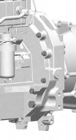
B . Disassembling and reassembling (Perkins 6-cylinder engine)
Preliminary operations
1. Apply the handbrake.
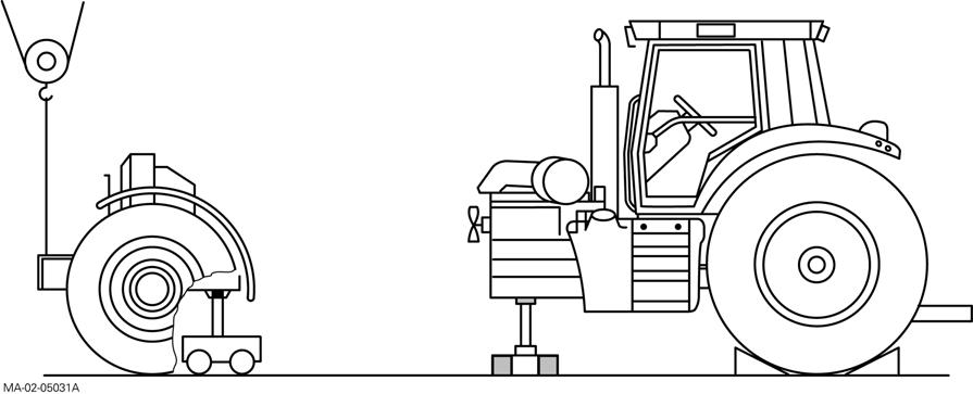
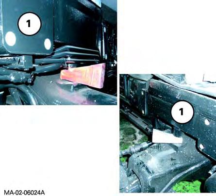
2. Ensure that the suspended front axle (if fitted) is in raised position and position chocks between the upper control arm and front axle housing (Fig.1).
3. Remove the bleed screw from the control unit (see chapter 9).
4. Remove the lateral panels from the engine and bonnet.
Servicing under the tractor
5. Remove the guard and the shaft (4WD tractors).
Servicing on the right-hand side of the tractor
6. Disconnect the batteries.
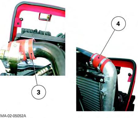
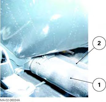
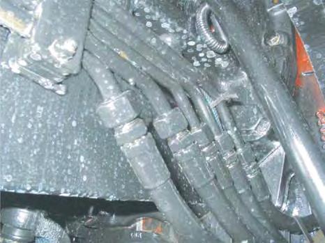
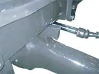
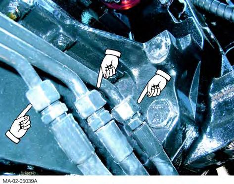
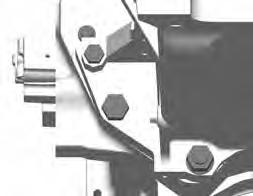
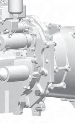
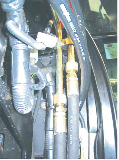
7. Mark then disconnect: -the differential lock hoses on the front axle, -the feed hose on the steering ram, -the lubricating hoses (running to and from the cooler) (Fig.2).
8. Remove the protection grille close to the radiator.
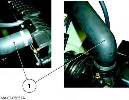
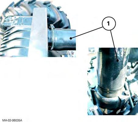
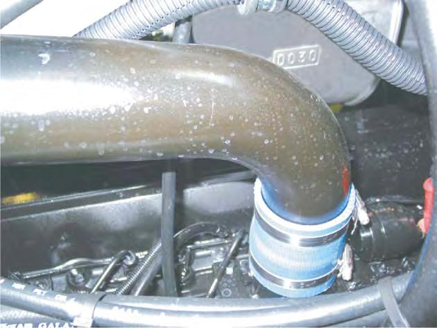
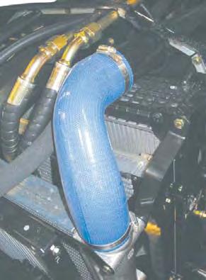
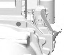
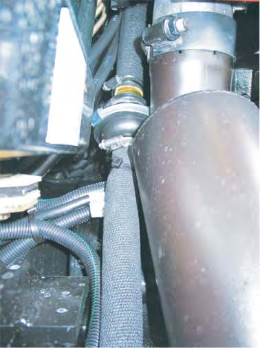
9. Disconnect the air sleeve (1) (turbo outlet) from the cooling sleeve (Fig.3).
Fig. 1
Fig. 2
Fig. 3
Splitting - Front frame / Perkins engine
Servicing on the left-hand side of the tractor
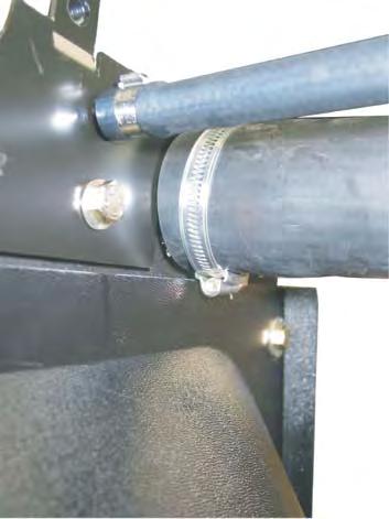
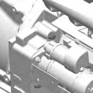
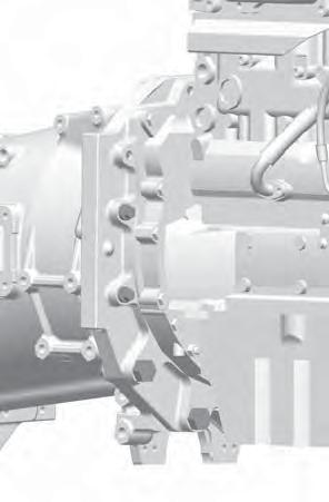
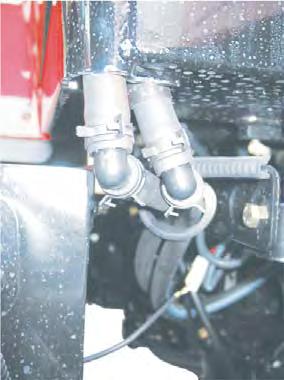
10. Mark then disconnect: -the feed hose on the steering ram, -the hoses (pressure-return and LS) on the rigid tubes (Fig.4) of the suspended front axle (if fitted).
11. Remove the protection grille close to the radiator.
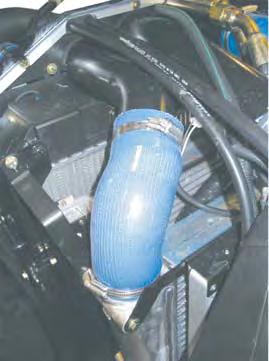
12. Disconnect the air sleeve (2) (intake on inlet manifold) from the cooling sleeve (Fig.5).
Draining the cooling system
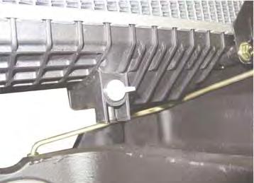
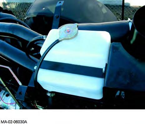
13. Unscrew the wing plug located on the left-hand side and front of the radiator. Drain the liquid into a clean container.
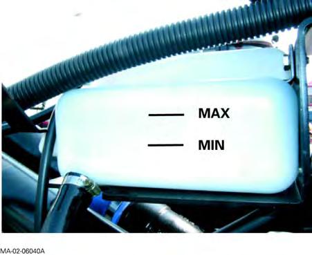
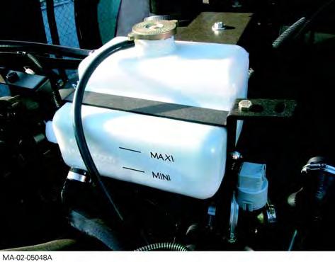
If the engine is hot, gradually loosen the expansion tank plug and remove it in order to expel the pressure from the circuit.
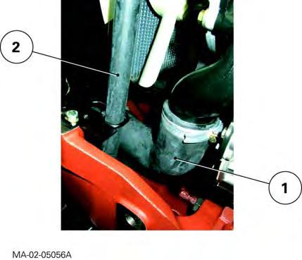
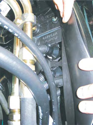
14. Disconnect the lower radiator hose (1) and the hose (2) linking the expansion tank to the base of the radiator (Fig.6).
Fig. 4
Fig. 5
Fig. 6
CLICK HERE TO DOWNLOAD THE COMPLETE MANUAL
• Thank you very much for reading the preview of the manual.
• You can download the complete manual from: www.heydownloads.com by clicking the link below
• Please note: If there is no response to CLICKING the link, please download this PDF first and then click on it.
CLICK HERE TO DOWNLOAD THE
Servicing above the engine
Splitting - Front frame / Perkins engine
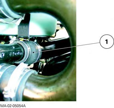
15. Disconnect the upper radiator hose (1) (Fig.7).
Servicing at the front of the tractor
16. Remove the weights (if fitted).
17. Separate the compressor, the condenser and the filter from their respective holders, and remove them carefully, without breaking the circuit (see chapter 12).
18. Mark and disconnect the wiring harnesses: -inside the grille, -on the control unit solenoid valves (suspended front axle, if fitted).
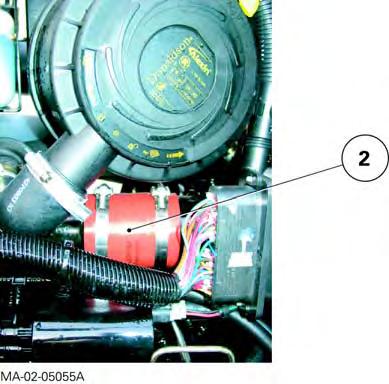
19. Disconnect the air sleeves (3) (4) on the air cooler located inside the grille (Fig.8).
Fig. 7
Fig. 8
Splitting - Front frame / Perkins engine
Preparing for disassembling
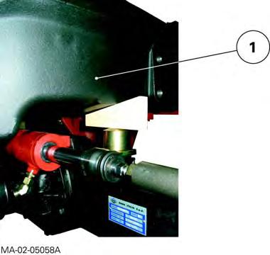
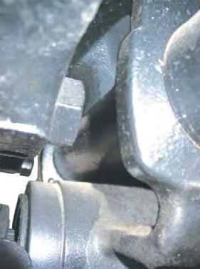
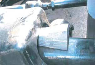
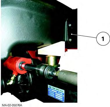
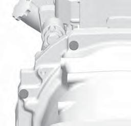
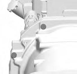
20. Cancel the front axle oscillation (all versions) by sliding a suitable chock in at each side of the support (1) (Fig.9).
21. Chock the rear wheels.
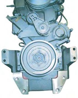
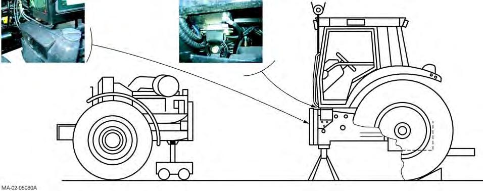
22. Install (Fig.11): -a mobile stand under the front axle beam, -a suitable sling under the front of the frame, -a fixed axle stand under the engine sump.
Disassembly
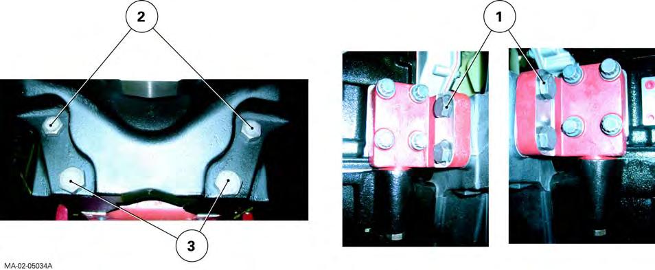
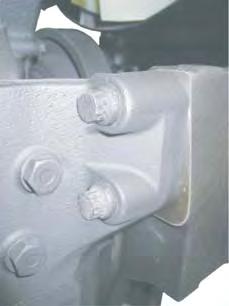
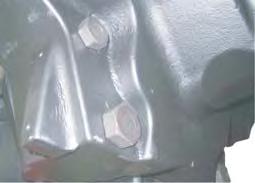
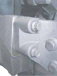
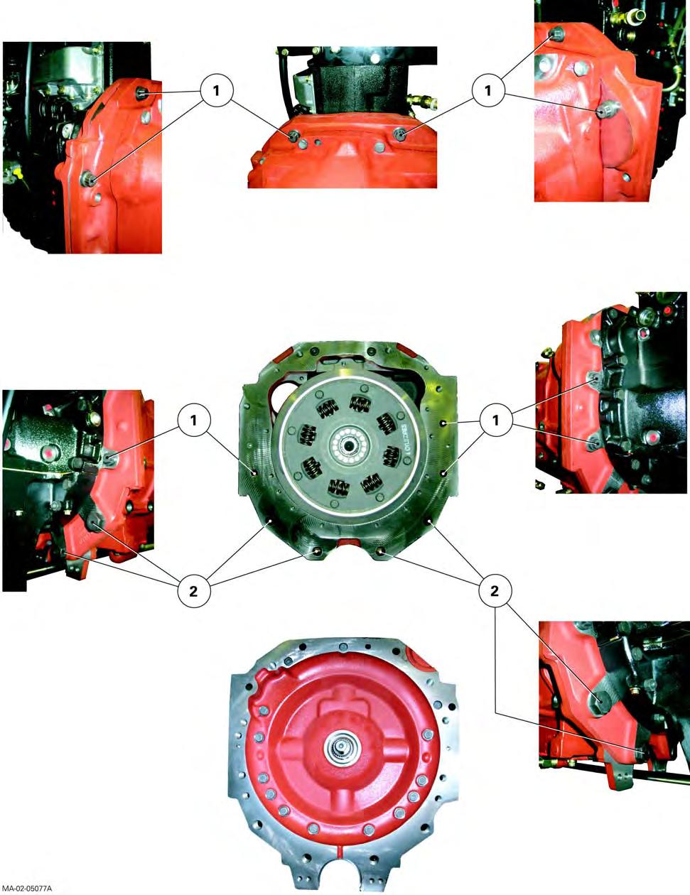
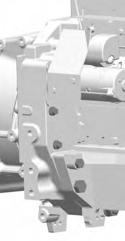
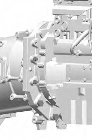
23. Remove lateral screws (1) (Fig.10).
24. With the help of an operator, loosen the screws (2)(3) (Fig.10), simultaneously moving the frame away from the engine.
When disassembling, use the sling to reduce the risk of toppling of the front frame assembly.
Screw dimensions
-M16 x 55 mm.
-M16 x 60 mm.
-M16 x 115 mm.
-M20 x 190 mm.
-M24 x 200 mm.
Reminder
When disassembling, check that connections (hoses, pipes and harnesses) are all disconnected.
Fig. 9
Splitting - Front frame / Perkins engine
Fig. 10
Splitting - Front frame / Perkins engine
Massey Ferguson 6400
Fig. 11
Splitting - Front frame / Perkins engine
Reassembly
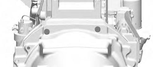
25. Clean the mating faces of the engine and front frame.
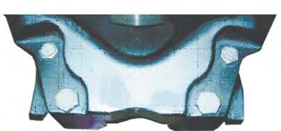
Special point
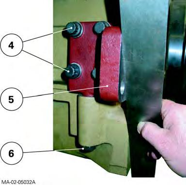
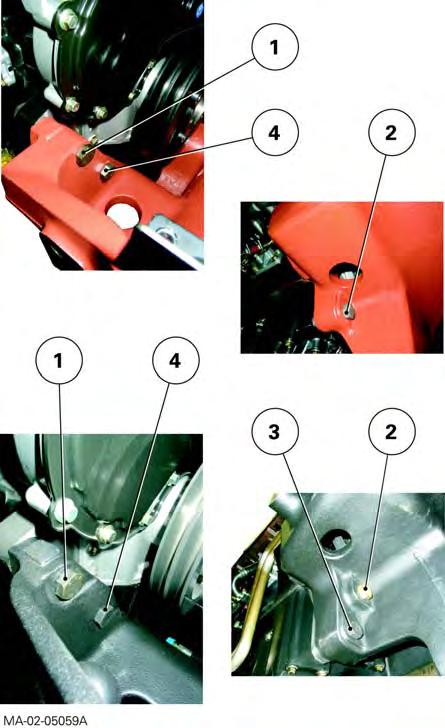
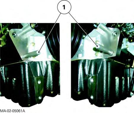
For tractors fitted with a Perkins six-cylinder engine, check with a ruler prior to assembly that the supports (5) are in line with the front face of the lower engine housing (Fig.13). If they are not, adjust the support(s) until they are correctly aligned. Tighten the screws to: -(4) 240 - 320 Nm (Loctite 270 or equivalent), -(6) 240 - 320 Nm.
Check correct alignment after tightening.
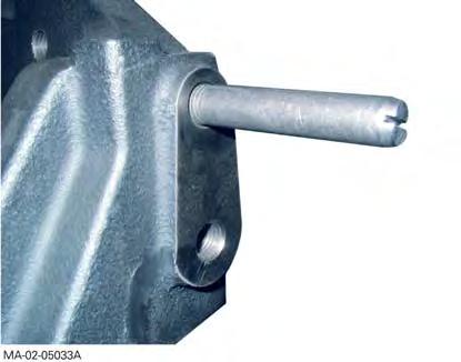
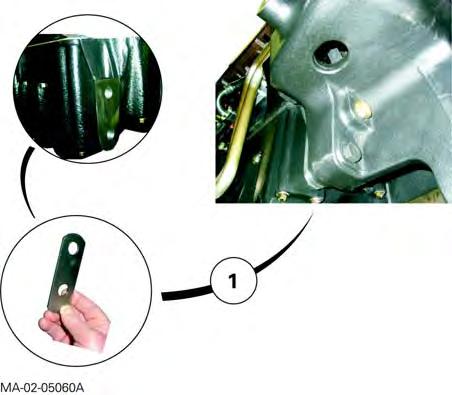
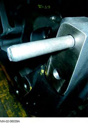
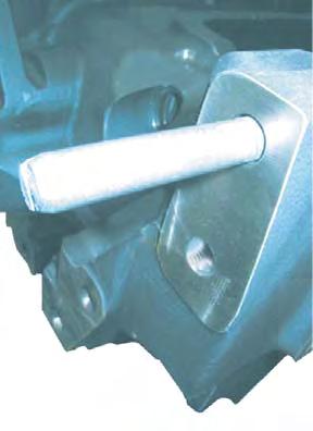
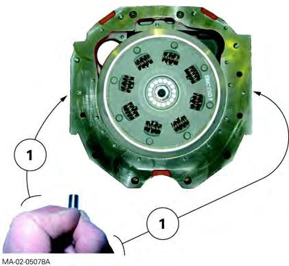
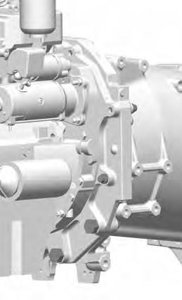
26. Screw a guide stud onto each rear face of the frame (Fig.12).
27. With the help of an operator, assemble the front frame onto the engine. Take out the guide studs.
28. Fit and tighten the diametrically opposed screws in the following order:
-Screw (2): 480-640 Nm.
-Screw (3): 800-1040 Nm.
-Screw (1): 240-320 Nm.
Final operations
Remark
Final operations are not especially difficult. They should be carried out in the reverse order to preliminary operations.
However, it will be necessary during reassembly to carry out the tightening torques, adjustments and tests described below.
Tightening torque
As required, wheel screws or nuts (see chapter 6).
Topping-up
-of coolant, to the maximum level marked on the expansion tank (Fig.14).
Fig. 12
Fig. 13
Splitting - Front frame / Perkins engine
Tests
-air conditioning system (if fitted – see chapter 12),
-cab suspension (if fitted – see chapter 12),
-All mechanical, hydraulic, electrical and electronic functions concerned by servicing.
Check tightness:
-of hydraulic unions
-of water hoses,
-of bleed screw on control unit of suspended front axle (if fitted)
Fig. 14
Fig. 15
Splitting - Front frame / Perkins engine
C . Disassembling and reassembling (Perkins 4-cylinder engine)
Reminder
There are two types of front frame. Each model corresponds to a specific engine type: Perkins engine with mechanical injection or Perkins EEM engine with electronic injection.
The frames are different in shape and assembly. Each front frame must be assembled to its corresponding engine.
Preliminary operations
29. Apply the handbrake.
30. Remove the side panels, prefilter (Perkins EEM engine), bonnet and side protection grilles.
Servicing under the tractor
31. Take off the guard, shaft and differential lock supply pipe (4WD tractors).
Servicing at the front of the tractor
32. Remove the front weights (if fitted).
33. Disconnect the batteries. Remove them if required (Perkins engine with mechanical injection).
Tractors with…
Battery location
Perkins engine with mechanical injection in the grille compartment
Perkins EEM enginebehind the right-hand footstep
Location of batteries
34. Detach the air conditioning compressor, condensor and filter from their respective supports (if fitted).
Place the assembly beside the tractor without disconnecting the pipes and hoses (see chapter12).
Splitting - Front frame / Perkins engine
Servicing inside the grille
35. Mark then disconnect: -electrical harnesses, -air sleeves(3) and (4) on the cooler (Perkins EEM engine- Fig.16).
Servicing on the right-hand side of the tractor
36. Mark and disconnect the feed hose on the steering ram.
37. Mark and disconnect the lubricating hoses running to and from the cooler (Perkins EEM engineFig.17).
38. Remove the protection grille close to the radiator.
39. Disconnect the air sleeve(1) (turbo outlet) from the cooling sleeve (Perkins EEM engine- Fig.18).
Fig. 16
Fig. 17
Fig. 18
Splitting - Front frame / Perkins engine
Servicing on the left-hand side of the tractor
40. Mark and disconnect the feed hose on the steering ram.
41. Remove the protection grille close to the radiator.
42. If necessary, disconnect the air sleeve(2) from the cooler inlet (intake manifold inlet- Perkins EEM engine- Fig.19).
Draining the cooling system
43. Unscrew the wing plug located on the front left-hand side of the radiator, to drain the circuit.
If the engine is hot, gradually loosen the expansion tank plug and remove it in order to release the pressure from the circuit.
44. Disconnect the lower radiator hose(1) and the hose(2) linking the expansion tank to the base of the radiator (Fig.20).
Servicing above the engine
45. Disconnect the upper radiator hose(1) (Fig.21 ).
Fig. 19
Fig. 20
Fig. 21
Splitting - Front frame / Perkins engine
Preparing for disassembling
46. Stop the front axle oscillation by sliding a suitable wooden chock either side of the support(1) (Fig.22).
47. Chock the rear wheels.
48. Install (Fig.25):
-a mobile stand under the front axle beam, -a suitable sling under the front of the frame, -a fixed axle stand under the engine sump.
Disassembly
Reminder
Before disassembling:
-check that the unions (hoses, pipes and harnesses) are all disconnected;
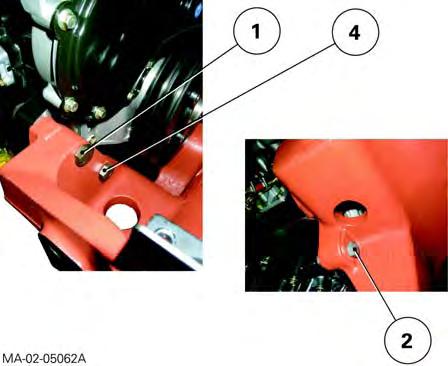
-note the position and location of chocks(1) inserted between the engine sump and front frame (Perkins EEM engine- Fig.23).
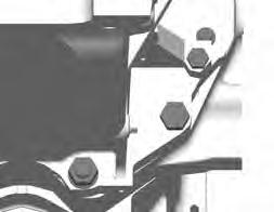
49. Loosen and remove (Fig.24):
-for Perkins engine with mechanical injection: screws and bolts(2), (4) and (1), -for Perkins EEM engine:screws and bolts(2), (3), (4) and (1).
With the help of an operator, gradually separate the engine front frame at the same time (Fig.25).
When disassembling, also use the sling to reduce the risk of toppling of the front frame assembly (Fig.25).
Fig. 22
Fig. 23
Splitting - Front frame / Perkins engine
Fig. 24
Fig. 25
Splitting - Front frame / Perkins engine
Dimensions of the screws and nuts
•Front frame and Perkins engine with mechanical injection
Screws Nuts
M16x75mm
M16x85mm
M16x115mm M16
•Front frame and Perkins EEM engine
Screws Nuts
M16x85mm
M16x95mm
M16x105mm
M16x120mm M16
Reassembly
Advice for use
Use guide studs to assist reassembly of the front frame and engine.
50. Clean the mating faces of the engine and front frame.
51. Screw two guide studs(1) to the front mating face of the engine (Fig.26).
52. With the help of an operator, assemble the front frame onto the engine as follows:
•Front frame and Perkins engine with mechanical injection (Fig.27)
53. Fit screws(2), (4) and nuts(1), simultaneously taking out the guide studs.
54. Tighten opposing screws and nuts to a torque of 240-320Nm in the following order (2)(4)(1).
•Front frame and Perkins EEM engine (Fig.28)
Reminder
If it is necessary to chock the front frame, refer to § D
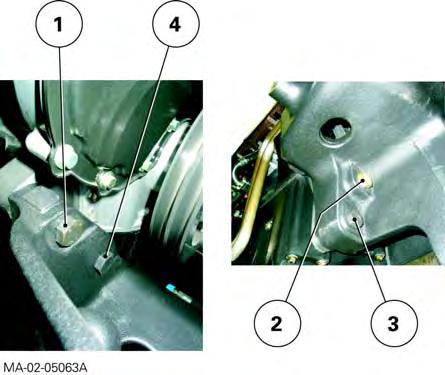
55. Fit screws(2), (3) and (4) and nuts(1), simultaneously taking out the guide studs.
56. Tighten opposing screws and nuts to a torque of 240-320Nm in the following order (2)(3)(4)(1).
Fig. 26
Fig. 27
Fig. 28
Splitting - Front frame / Perkins engine
Final operations
Remark
Final operations are not especially difficult. They are carried out in reverse order to the preliminary operations. However, during reassembly, the tightening torques, settings and tests outlined below must be carried out.
Tightening torque:
-as required, wheel screws or nuts (see chapter6).
Topping-up:
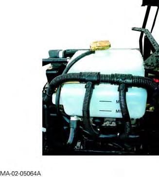
-of coolant, to the maximum level marked on the expansion tank (Fig.29).
Tests:
-air conditioning system (if fitted) (see chapter12), -cab suspension (if fitted) (see chapter12), -all mechanical, hydraulic, electrical and electronic functions concerned by servicing.
Check tightness:
-of hydraulic unions, -of water hoses.
Fig. 29
CLICK HERE TO DOWNLOAD THE COMPLETE MANUAL
• Thank you very much for reading the preview of the manual.
• You can download the complete manual from: www.heydownloads.com by clicking the link below
• Please note: If there is no response to CLICKING the link, please download this PDF first and then click on it.
CLICK HERE TO DOWNLOAD THE
Splitting - Front frame / Perkins engine
D . Shimming the front frame (Perkins 4-cylinder EEM engine)
Special point
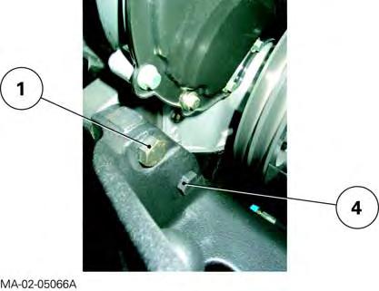
When the front frame is fitted to the Perkins EEM engine, the mating face of the engine sump is not in contact with the mating face of the front frame. It is therefore advised to fill this space with shims(1) (Fig.30) whose thickness will be measured and set afterwards.
Reminder
Shimming should only be carried out if the front frame and or engine has / have been replaced.
57. With the help of an operator, assemble the front frame onto the engine.
Preparing for shimming (Fig.31)
58. Fit only screws(4) and nuts(1), simultaneously taking out the guide studs.
59. Tighten opposing screws and nuts to a torque of240-320Nm in the following order (4)(1).
Fig. 30
Fig. 31
Splitting - Front frame / Perkins engine
Shimming
Important
To avoid applying undue loads to the mating faces during shimming, avoid adjusting the safety stands placed under the engine and front frame during disassembly.
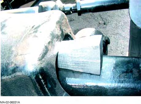
60. Using two stacked shims(1), each at least 2.30mm thick (Fig.32), measure the gap between the mating faces of the engine sump and front frame.
Determine the thickness of shims to be fitted by increasing, as required, the thickness of each shim until they fit tightly in the gap.
Remark
Shimming is carried out using shims between 2.30 and 2.60mm thick.
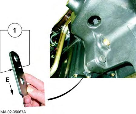
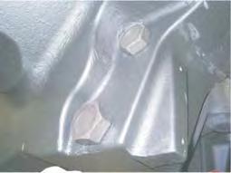
Inserting shims between the front frame and the engine
61. Slightly loosen the screws(4) and bolts(1) (Fig.31).
62. Position the shims(1): the endE should be turned downwards. Insert them between the front frame and the engine sump (Fig.32).
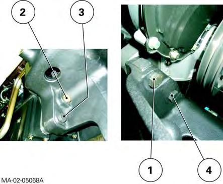
63. Fit screws(2) and (3) (Fig.33).
64. Tighten opposing nuts and all screws of the front frame to a torque of 240-320Nm in the following order (2)(3)(4)(1) (Fig.33).
65. Release the safety stands.
Fig. 32
Fig. 33
Splitting - Front frame / Perkins engine
Massey Ferguson 6400
2A20
- Splitting - Front frame / Sisu engine
CONTENTS
A.General
B.Disassembling
C.Reassembling.
Splitting - Front frame / Sisu engine
Massey Ferguson 6400
Splitting - Front frame / Sisu engine
A . General
The front frame and engine must be disassembled when the assemblies need to be replaced, or when servicing is necessary on one of the mechanical elements located at the front of the engine.
Remark
This section presents a general disassembly procedure. Before and during disassembly, check that all connections have been properly separated between the fixed assembly and mobile assembly
B . Disassembling
Preliminary operations
1. Put on the handbrake if necessary.
Remark
Putting on the handbrake is optional because the Park Lock mechanism (option) automatically immobilises the tractor when stationary.
2. Ensure that the suspended front axle (if fitted) is in raised position and position chocks between the upper control arm and front axle housing (Fig.1). Remove the bleed screw from the control unit (see chapter 9).
3. Remove the lateral panels from the engine and bonnet.
Servicing under the tractor
4. Remove the guard and the 4WD shaft located under the engine.
Fig. 1
Splitting - Front frame / Sisu engine
Servicing on the right-hand side of the tractor
5. Disconnect the batteries.
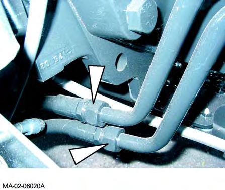
6. Mark then disconnect: -the differential lock hoses on the front axle, -the feed hose on the steering ram, -the lubricating hoses running to and from the cooler (Fig.2).
7. Remove the protection grille close to the radiator.
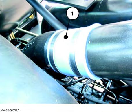
8. Disconnect the air sleeve (1) (turbo outlet) from the cooling sleeve (Fig.3).
Servicing on the left-hand side of the tractor
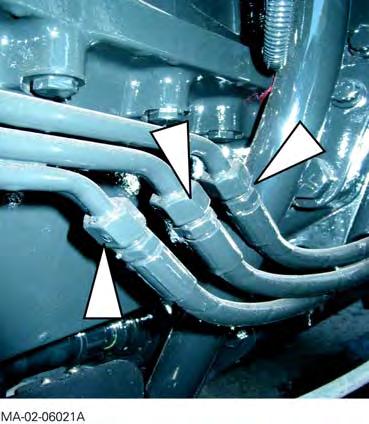
9. Mark then disconnect: -the feed hose on the steering ram, -the hoses (pressure-return and LS) on the rigid tubes (Fig.4) of the suspended front axle (if fitted).
10. Remove the protection grille close to the radiator.
Fig. 2
Fig. 3
Fig. 4
Splitting - Front frame / Sisu engine
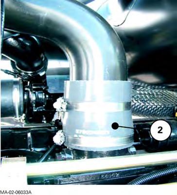
11. Disconnect the air sleeve (2) (intake on inlet manifold) from the cooling sleeve (Fig.5).
Draining
the cooling system
12. Unscrew the wing plug located on the left-hand side and front of the radiator. Drain the liquid into a clean container.
If the engine is hot, gradually loosen the expansion tank plug and remove it in order to drive the pressure from the circuit.
13. Disconnect the lower radiator hose (1) and the hose (2) linking the expansion tank to the base of the radiator (Fig.6).
Servicing above the engine
14. Disconnect the upper radiator hose (1) (Fig.7).
Servicing at the front of the tractor
15. Remove the weights (if fitted).
16. Separate the compressor, the condenser and the filter from their respective holders, and remove them carefully, without breaking the circuit (see chapter 12).
17. Mark and disconnect the wiring harnesses: -inside the grille, -on the control unit solenoid valves (suspended front axle, if fitted).
Fig. 5
Fig. 6
Fig. 7
Splitting - Front frame / Sisu engine
18. Disconnect the air sleeve (3)(4) on the air cooler located inside the grille (Fig.9).
Preparing for disassembling
19. Cancel the front axle oscillation (all versions) by sliding a suitable chock in at each side of the support (1) (Fig.8).
20. Chock the rear wheels.
21. Install (Fig.11):
-a mobile stand under the front axle beam, -a suitable sling under the front of the frame, -a fixed axle stand under the engine sump.
Disassembling
22. Remove lateral screws (1) (Fig.10).
23. With the help of an operator, loosen the screws (2)(3) (Fig.10), simultaneously moving the frame away from the engine.
When disassembling, use the sling to reduce the risk of toppling of the front frame assembly.
Screw dimensions
-M16 x 100
-M20 x 150
-M24 x 165
Reminder
When disassembling, check that connections (hoses, pipes and harnesses) are all disconnected.
Fig. 8
Fig. 9
Splitting - Front frame / Sisu engine
Fig. 10
Fig. 11
Splitting - Front frame / Sisu engine
C . Reassembling
24. Clean the mating faces of the engine and front frame.
25. Screw a guide studs onto each rear face of the front frame (Fig.12).
26. With the help of an operator, assemble the front frame onto the engine. Take out the guide studs.
27. Fit and tighten the diametrically opposed screws (Fig.10) in the following order:
-Screw (2): 480 -640 Nm,
-Screw (3): 800 -1040 Nm,
-Screw (1): 240 -320 Nm.
Final operations
Remark
Final operations are quite simple, and should therefore be carried out in the reverse order to preliminary operations.
However, it will be necessary during reassembly to carry out the tightening torques, checks and tests described below.
Tightening torques
-As required, wheel screws or nuts (see chapter 6).
Topping-up
-of coolant, to the maximum level marked on the expansion tank (Fig.13).
Testing
-air conditioning mechanism (if fitted – see chapter 12),
-suspended front axle (if fitted – see chapter 8),
-all mechanical, hydraulic, electrical and electronic functions concerned by servicing.
Checking tightness
-of hydraulic unions, -of water hoses,
-of bleed screw on control unit of suspended front axle (if fitted).
Fig. 12
Fig. 13
Splitting the front frame/Sisu engine - MF6497-6499
2A30 - Splitting the front frame/Sisu engineMF6497-6499
CONTENTS
A.General
B.Disassembly.
C.Reassembly
Splitting the front frame/Sisu engine - MF6497-6499
Massey Ferguson
Splitting the front frame/Sisu
A . General
The front frame and engine must be split when the assemblies need to be replaced, or when servicing is necessary on one of the mechanical elements located at the front of the engine.
IMPORTANT: This section presents a general disassembly procedure. Before and during disassembly, check that all connections have been properly separated between the fixed assembly and mobile assembly.
Splitting the front frame/Sisu engine - MF6497-6499
B . Disassembly
Preliminary operations
1. Apply the handbrake.
2. Check that the suspended front axle (if fitted) is in high position.
Position chocks between the upper control arms and front axle housing (Fig.1).
3. Remove the bleed screw from the control unit (if fitted, see chapter 9).
4. Take off:
-the side panels either side of the engine, -the bonnet (if necessary).
Servicing under the tractor
5. Mark then disconnect the two ends of the hoses fixed to the 4WD transmission shaft guards (front and rear). Block their openings.
6. Remove the guards and 4WD transmission shaft.
Servicing on the right-hand side of the tractor
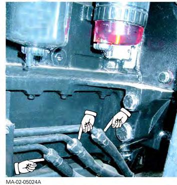
7. Disconnect the batteries.
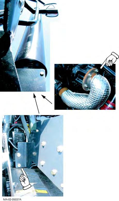
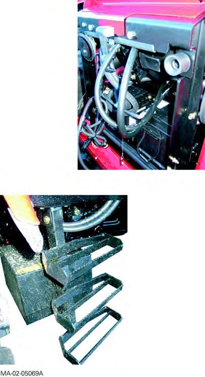
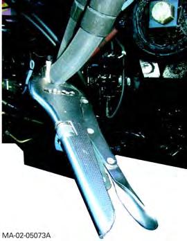
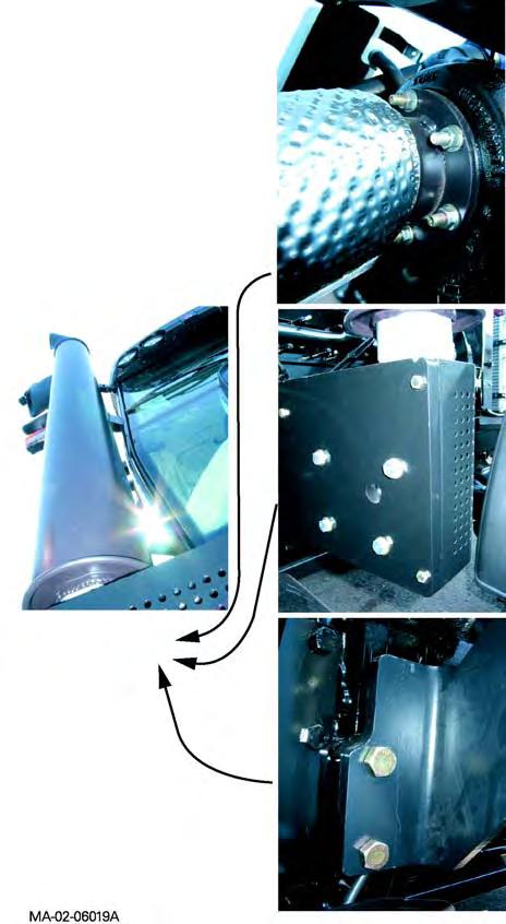
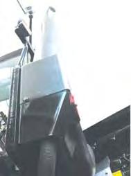
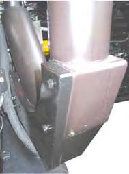
8. Take off: -the front mudguard; -the vertical exhaust assembly (including support); -the side engine reinforcement; - the protection grille close to the radiator.
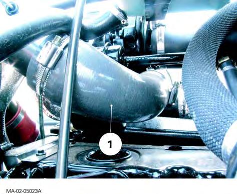
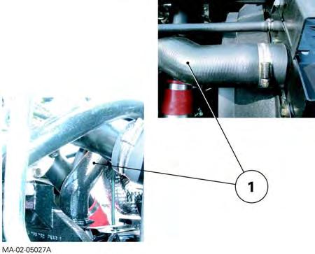
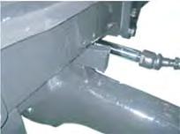
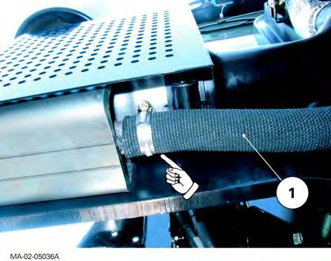
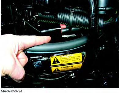
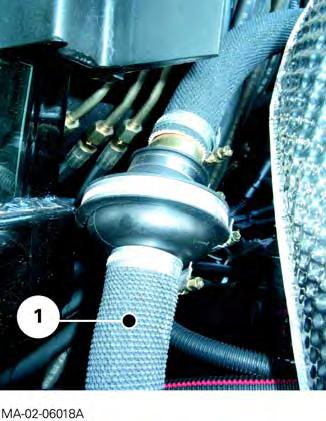
9. Disconnect: -the turbocharger outlet air sleeve (1) (Fig.2); -the flexible air filter sleeve.
MA-02-05110A
Fig. 1 1
MA-02-05111A
Fig. 2
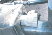
MA-02-05112A
Fig. 3
Splitting the front frame/Sisu engine -
Servicing on the left-hand side of the tractor
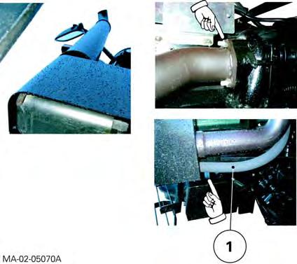
10. Remove the front mudguard.
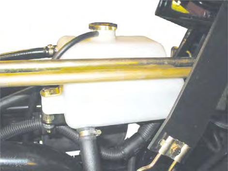
11. Remove or move the fuel tank apart the side of the tractor.
12. Take off: -the side engine reinforcement; - the protection grille close to the radiator.
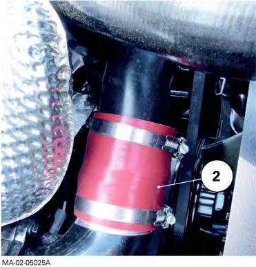
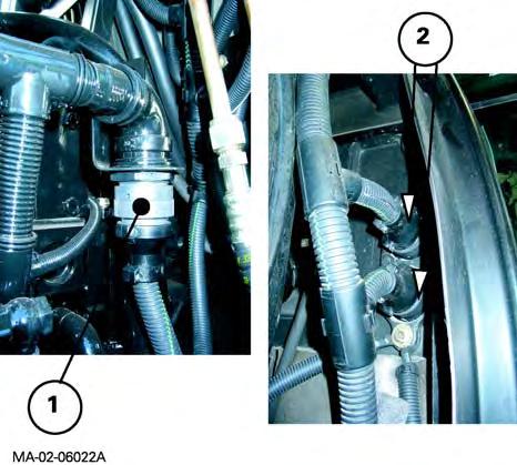
13. Disconnect the intake air manifold sleeve (2) (Fig.3).
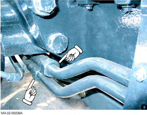
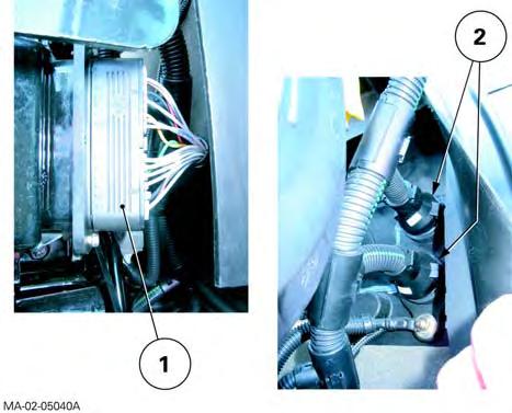
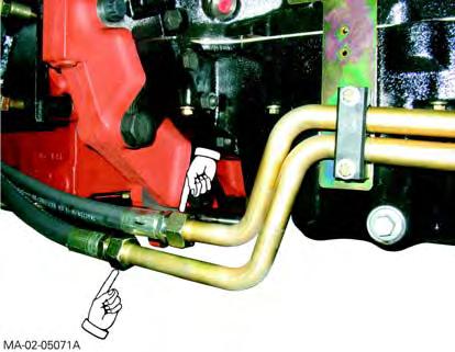
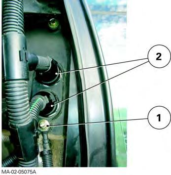
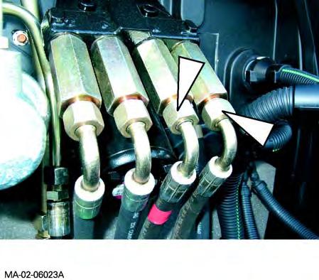
14. Disconnect (Fig.4): -the rigid pipes (1) (pressure, return and LS) to the suspended front axle (if fitted); -the rigid pipes (2) to the front linkage (if fitted).
Draining the cooling system
15. Unscrew the wing plug (1) located on the left-hand side and front of the radiator (Fig.5). Drain the liquid into a clean container.
DANGER: If the engine is hot, before loosening the wing plug (1), gradually loosen the expansion tank plug and remove it in order to expel the pressure from the circuit.
16. Disconnect the lower radiator hose (1) and the hose (2) linking the expansion tank to the base of the radiator (Fig.6).
Fig. 4
MA-02-05114A
Fig. 5
Fig. 6
Splitting the front frame/Sisu engine - MF6497-6499
Servicing above the engine
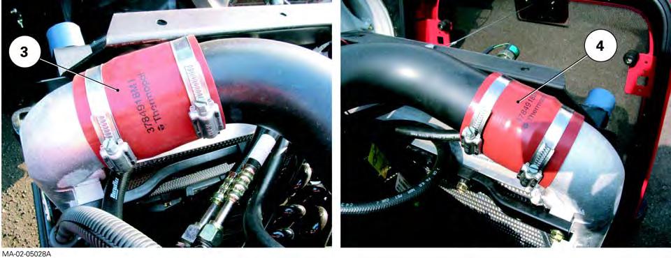
17. Take off:
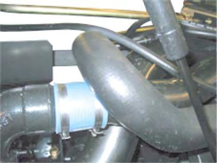
-the sleeve (3) and the rigid air sleeve (5) of the air cooler inlet (Fig.7);
-the sleeve (4) and the rigid air sleeve (6) of the air cooler outlet (Fig.8);
18. Disconnect:
-the flexible particle suction sleeve between the air filter and the exhaust;
-the lubricating pipes/hoses connecting the rear axle right-hand hydraulic cover to the oil cooler.
19. Disconnect:
-the thermostatic fan ENG 19 connector; -the upper hose (1) and the hose (2) linking the expansion tank to the top of the radiator (Fig.9).
Servicing at the front of the tractor
20. Take off:
-the front weights (if fitted); -the centre weight (if fitted).
21. Detach the air conditioning compressor, condenser and filter from their respective supports. Carefully keep them apart without opening the circuit (see chapter12).
IMPORTANT: If the air conditioning circuit should be open, see chapter12 before any action.
22. Mark and disconnect the wiring harnesses: -inside the grille;
-on the control unit solenoid valves (suspended front axle, if fitted).
MA-02-05115A
Fig. 7
MA-02-05116A
Fig. 8
MA-02-05117A
Fig. 9
CLICK HERE TO DOWNLOAD THE COMPLETE MANUAL
• Thank you very much for reading the preview of the manual.
• You can download the complete manual from: www.heydownloads.com by clicking the link below
• Please note: If there is no response to CLICKING the link, please download this PDF first and then click on it.
CLICK HERE TO DOWNLOAD THE
Splitting the front frame/Sisu engine -
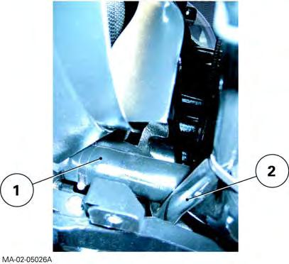
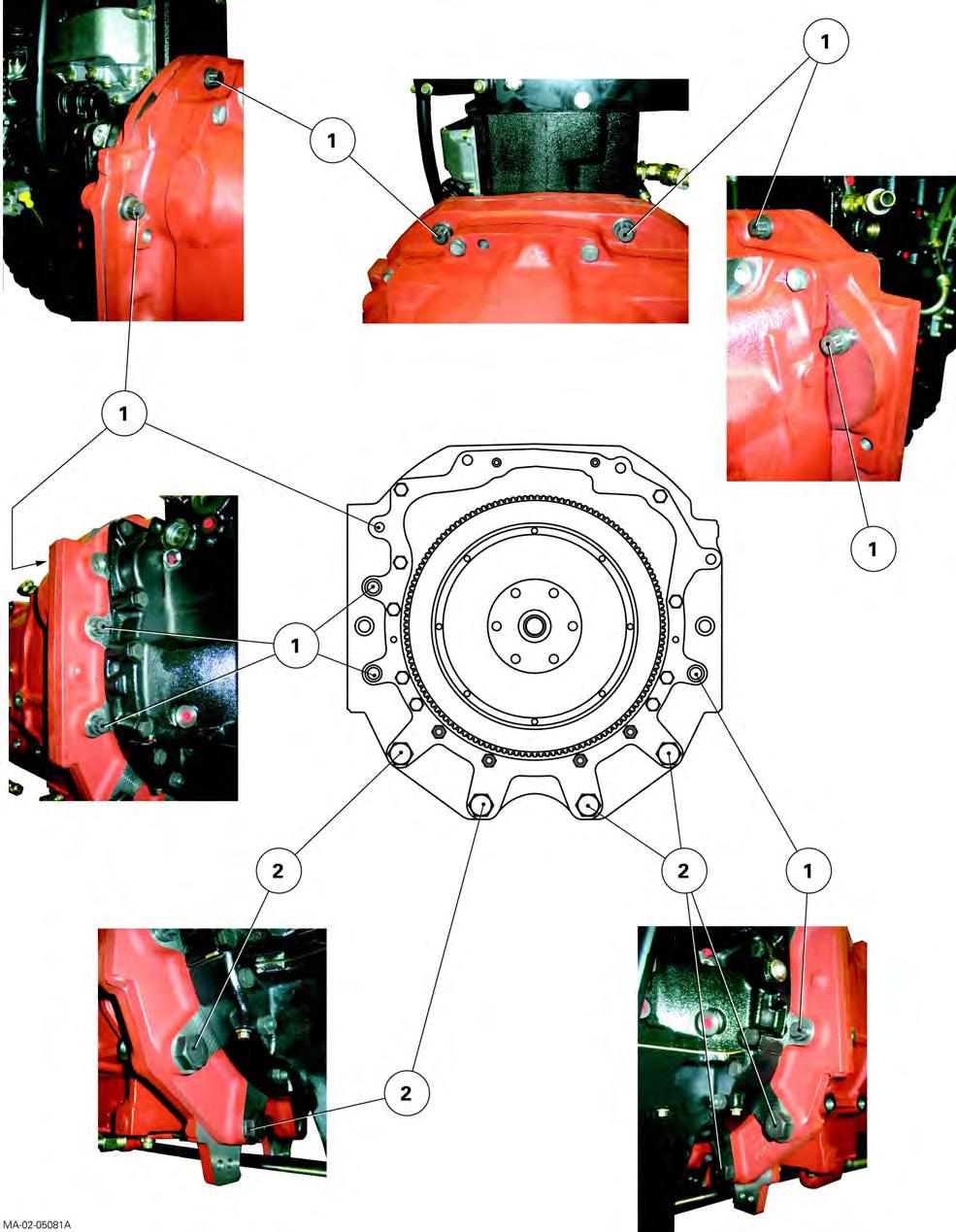
Disassembly
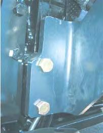
The lower screws M20x135 (2) and M24x165 (3), attaching the front frame to the lower engine housing, are not accessible on 4WD tractors (Fig.10). These screws are facing the drive pinion carrier, which also serves as a steering ram support.
Front frame / engine splitting takes place in two steps: -first step: removing the front axle (fixed or suspended);
-second step: splitting the front frame (radiators/cooler) from the engine
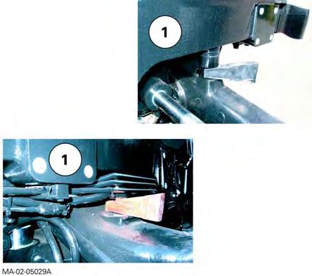
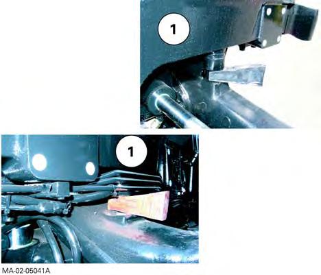
First step: removing the front axle (fixed or suspended, see chapter8)
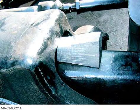
23. Cancel the front axle oscillation (all versions) by sliding a suitable chock in at each side of the frame and front axle (1) (Fig.11).
24. Chock the rear wheels.
25. Remove the front wheels.
26. Install (Fig.12):
-a fixed stand at the front of and under the gearbox;
-a fixed stand under the engine.
MA-02-05118A
Fig. 10
MA-02-05119A
Fig. 11
MA-02-05120A
Fig. 12
Splitting the front frame/Sisu engine - MF6497-6499
27. Remove the suspended front axle control block (if fitted, see chapter9).
28. Remove (see chapter8): -the first bearing of the fixed or suspended (according to version) front axle; -the front axle.
Second step: splitting the front frame (radiators/cooler) from the engine.
29. Correctly sling and balance the front frame assembly (radiators/cooler), using the tapped holes drilled into each side of the front frame (Fig.14).
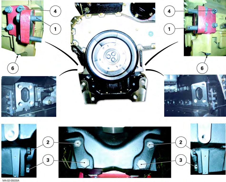
30. Loosen one M16x85 side screw (1) on the left and right-hand side of the engine (Fig.13). Replace with a guide stud of appropriate length.
31. With the help of an operator, loosen the screws (2) (3) (Fig.13).
32. Remove the front frame from the engine.
Screw dimensions (Fig.13)
Screw
M16x85 (1)
M20x135 (2)
M24x165 (3)
Fig. 13 MA-02-05122A
Fig. 14
Splitting the front frame/Sisu engine - MF6497-6499
C . Reassembly
33. Clean the mating faces of the engine and front frame.
34. Screw a guide studs onto each rear face of the front frame (Fig.15).
35. With the help of an operator, assemble the front frame onto the engine.
36. Tighten two screws (1) (Fig.13). Take out the guide studs. Fit and tighten the diametrically opposed screws (Fig.13) in the following order: -screws (1) to a torque of 240-320Nm; -screws (2) to a torque of 480-640Nm; -screws (3) to a torque of 800-1040Nm.
Fig. 15
Splitting the front frame/Sisu engine -
Final operations
Final operations are not especially difficult. They therefore will be carried out in the reverse order of the preliminary operations.
However, the following operations need to be performed during refitting:
-if necessary, tighten the screws or wheel nuts at the required tightening torque (see chapter6);
-make up the level of coolant, to the maximum level marked on the expansion tank (Fig.16);
- test:
-the air conditioning system (if fitted - see chapter12);
-the suspended front axle (if fitted, see chapter 8), -all mechanical, hydraulic, electrical and electronic functions concerned by servicing;
- check the tightness:
-of the hydraulic unions, -of water hoses,
-of the bleed screw on control unit of suspended front axle (if fitted).
MA-02-05124A
Fig. 16
Splitting the front frame/Sisu engine - MF6497-6499
Massey Ferguson
2B10 - Splitting - Perkins Engine / GBA20 Gearbox
CONTENTS
A.General
B.Disassembling and reassembling (Perkins 6-cylinder engine)
C.Disassembling and reassembling (Perkins 4-cylinder engine)
Massey Ferguson 6400
Splitting - Perkins Engine / GBA20 Gearbox
A . General
On MF6400 series tractors fitted with a GBA20 gearbox, two types of engine may be fitted:
-Perkins 6-cylinder engine.
-Perkins 4-cylinder engine.
It is required to split the tractor between the engine and the gearbox when access is necessary to carry out servicing on the main following elements:
Engine interface
•Transmission damper
•Engine flywheel
•Engine adapter plate
Gearbox interface
•Spacer and sealing ring
•Internal hydraulic pipes
•Reverse shuttle and the Dynashift
Remark
-This section presents a general disassembly procedure. Before and during disassembly, check that all connections have been properly separated between the fixed assembly and mobile assembly.
-The cab remains attached to the centre housing.
Splitting - Perkins Engine / GBA20 Gearbox
B . Disassembling and reassembling (Perkins 6-cylinder engine)
Preliminary operations
1. Apply the handbrake.
2. Check that the suspended front axle (if fitted) is in low position and unscrew the control unit bleed screw (see chapter 9).
3. Remove the lateral panels from each side of the engine and bonnet (if necessary).
Servicing under the tractor
4. Remove the guard and the shafts (4WD tractors).
Servicing at the front of the tractor
5. Remove the front weights (if fitted).
Servicing on the right-hand side of the tractor
6. Remove the footstep.
7. Disconnect and remove first the batteries and then the support.
8. Disconnect the flexible sleeve (1) (Fig.1) fitted to the suction port. Remove the vertical exhaust assembly (including support Fig.2).
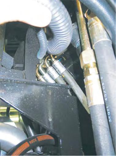
9. Mark then disconnect: -the cables (positive and negative) on the starter, -the front differential lock hose, -the hose on the steering ram, -the lubricating hoses (running to and from the cooler) (Fig.3).
Fig. 1
Fig. 2
Splitting - Perkins Engine / GBA20 Gearbox
Servicing on the left-hand side of the tractor
10. Remove the footstep.
11. Mark then disconnect: -the hose on the steering ram, -the hoses (pressure-return and LS) on the rigid pipes (Fig.4) of the suspended front axle (if fitted).
12. Mark and disconnect the fuel feed and return hoses on the engine (block ports immediately).
Remark
If the fuel tank is not removed it obstructs access to the engine attachment screw on the spacer, but does not prevent access. However, if there is a problem, remove the tank having previously marked and disconnected: -the gauge harness, -the vent hose on the tank.
Servicing under the cab
13. Mark, toe-in and disconnect the heating hoses, immediately blocking the ports.
Fig. 3
Fig. 4
CLICK HERE TO DOWNLOAD THE COMPLETE MANUAL
• Thank you very much for reading the preview of the manual.
• You can download the complete manual from: www.heydownloads.com by clicking the link below
• Please note: If there is no response to CLICKING the link, please download this PDF first and then click on it.
CLICK HERE TO DOWNLOAD THE
Splitting - Perkins Engine / GBA20 Gearbox
Servicing the engine
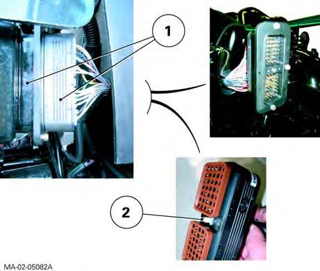
14. If necessary disconnect the connector (1) of the main wiring harness (Fig.5).
15. Separate the compressor, the condenser and the filter from their respective holders, and remove them carefully, without breaking the circuit (see chapter 12).
Remark
Work carefully.
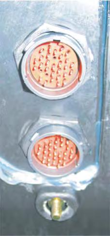
Servicing at the front of the cab
16. Disconnect the connectors (2) on the left-hand face of the fire wall (Fig.5).
Preparing for disassembling
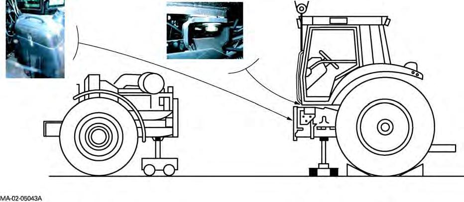
17. Cancel the front axle oscillation (all versions) by sliding a suitable chock in at each side of the support (1) (Fig.6).
18. Chock the rear wheels.
19. Install (Fig.7): -a fixed stand at the front of the gearbox, -a mobile stand at the back of the engine.
20. If necessary, separate the cab from the front rightand left-hand supports. Gently lift it using two straps fitted to the lateral handles. Fit a wooden chock temporarily between the cab and the supports.
Fig. 5
Fig. 6
Splitting - Perkins Engine / GBA20 Gearbox
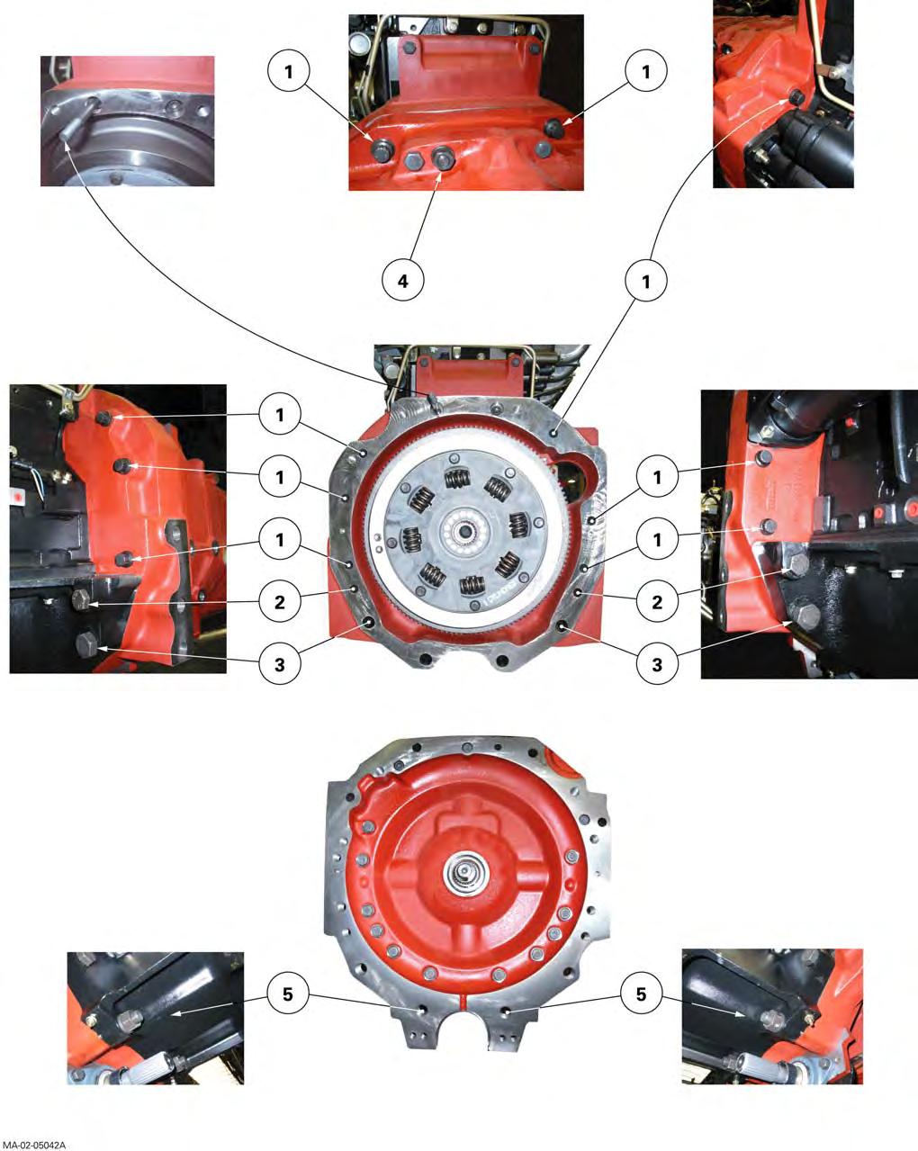
Disassembly
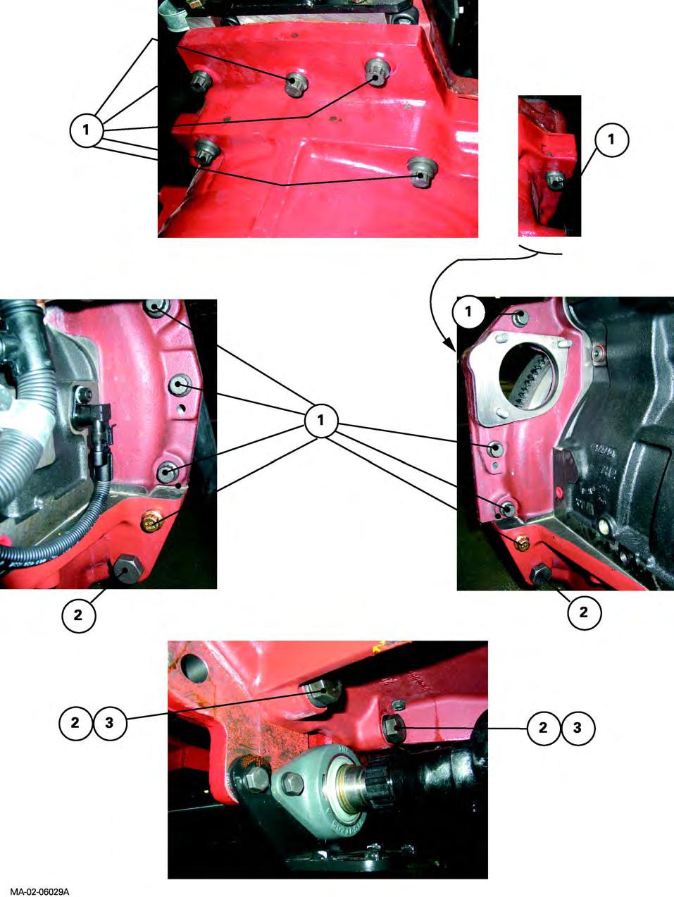
21. Remove the screws and nuts attaching the engine to the gearbox (Fig.8). Mark their lengths and positionings.
22. With the help of an operator, separate the assemblies (Fig.7).
Reminder
When disassembling, check that connections (hoses, pipes and harnesses) are all disconnected.
Dimensions of the screws, studs and nuts
Screws
-M16 x 60 mm
-M16 x 115 mm
-M16 x 185 mm
-M22 x 160mm
Studs
-M12 x 185 mm
-M22 x 160 mm
Nuts
-M12
-M22
Fig. 7
Massey Ferguson
Fig. 8
Splitting - Perkins Engine / GBA20 Gearbox
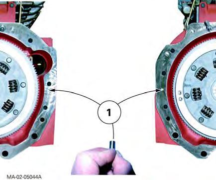
Reassembly
23. Clean the mating faces of the engine and the gearbox spacer.
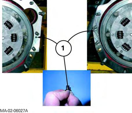
24. Check:
-the presence of locating pins (1) on the engine (Fig.9), -the tightness of the upper nut (M12) on the engine adapter plate (Loctite 270), - the tightness of the lower studs (M22) on the gearbox spacer (Loctite 270).
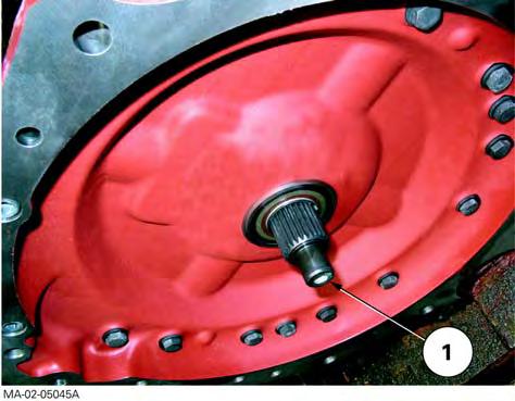
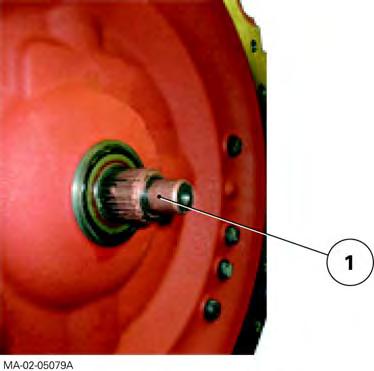
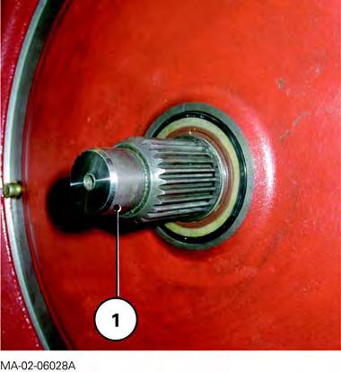
25. Lightly lubricate the splines of main shaft (1) (Fig.10) with grease (type GN + Molykote) or equivalent.
26. If necessary screw two supplementary diametrically opposed guide studs into the gearbox.
27. Assemble the engine onto the gearbox spacer.
Reminder
If necessary, remove the starter and turn the flywheel ring gear using a suitable tool. This will ease the engagement of the vibration damper splines with those of the main shaft. If there is resistance, do not force it and find the cause of the problem.
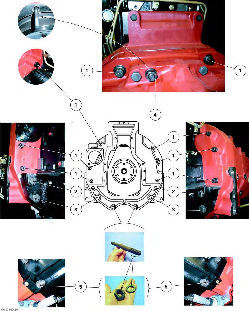
28. When the elements are joined, remove the guide studs (if fitted). Lightly grease the thread of the screws and nuts with Loctite 270 or equivalent and refit according to the marks made at disassembly. Tighten to the required torques (Fig.11)
-Screw (1): 240 - 320 Nm.
-Screw (2): 240 - 320 Nm.
-Screw (3): 630 - 840 Nm.
-Nuts (4): 100 - 130 Nm.
-Nuts (5): 630 - 840 Nm.
Fig. 9
Fig. 10
Massey Ferguson
Fig. 11
Splitting - Perkins Engine / GBA20 Gearbox
Final operations
Remark
Final operations are not especially difficult. They should be carried out in the reverse order to preliminary operations. However, it will be necessary during reassembly to carry out the tightening torques, adjustments and tests described below.
Tightening torques
As required:
•Front cab attachment screw (see chapter 12).
•Screw (2) of connector (1) on main wiring harness (Fig.5 and Fig.12) 2.82 to 3.15 Nm
Topping-up of coolant to the maximum level marked (radiator, expansion tank. Fig.13).
Tests
-air conditioning system (if fitted – see chapter 12).
-Cab suspension (if fitted, see chapter 12).
-All mechanical, hydraulic, electrical and electronic functions concerned by servicing.
Checking tightness
-Hydraulic unions.
-Bleed screw on control unit of suspended front axle (if fitted).
Fig. 12
Fig. 13
Splitting - Perkins Engine / GBA20 Gearbox
C . Disassembling and reassembling (Perkins 4-cylinder engine)
Preliminary operations
29. Apply the handbrake.
30. Remove the side panels, prefilter (Perkins EEM engine) and bonnet.
Servicing under the tractor
31. Take off the guard, shaft and differential lock supply pipe (4WD tractors).
Servicing at the front of the tractor
32. Remove front the weights (if fitted).
33. Disconnect the batteries.
Tractors with… Battery location
Perkins engine with mechanical injection in the grille compartment
Perkins EEM enginebehind the right-hand footstep
Location of batteries (Fig.14)
Fig. 14
Splitting - Perkins Engine / GBA20 Gearbox
Servicing on the right-hand side of the tractor
34. Take off the front right-hand mudguard.
35. Disconnect the flexible sleeve(1) (Fig.15) fitted to the suction port. If necessary, remove the vertical exhaust assembly (including support) (Fig.15).
36. Mark then disconnect: -the hose on the steering ram or on the spool valve (Orbitrol), depending on the tractor type; -the lubricating hoses (running to and from the cooler) (Perkins EEM engine) (Fig.16).
Servicing on the left-hand side of the tractor
37. Take off the front left-hand mudguard.
38. Mark then disconnect: -the hose on the steering ram or on the spool valve (Orbitrol), depending on the tractor type; -the gas-oil supply and return hoses on the engine. Immediately block the ports.
39. Disconnect the cables connected to the starter positive terminal (Fig.17).
Fig. 15
Fig. 16
Fig. 17
Splitting - Perkins Engine / GBA20 Gearbox
Servicing under the cab
If the engine is still hot, allow it to cool.
Reminder
To work on heating hoses, it is not necessary to drain the engine block cooling circuit.
40. Toe-in each heating hose using a clamp fitted with plastic jaws (Fig.18).
Servicing the engine
41. Mark and disconnect the heating hoses on the engine block and water pump. Immediately block the ports using suitable plugs.
42. Disconnect the negative cables on the block at the rear left-hand side of the engine (Fig.19).
43. If necessary disconnect the connector(1) of the main wiring harness (Perkins EEM engine) (Fig.19).
44. Detach the air conditioning compressor, condensor and filter from their respective supports (if fitted).
Place the assembly beside the tractor without disconnecting the pipes and hoses (see chapter12).
Note: Carry out this procedure with care.
Fig. 18
Fig. 19
Splitting - Perkins Engine / GBA20 Gearbox
Servicing at the front of the cab
45. Disconnect the connectors(2) and the ground terminals(1) on the left-hand side of the cab wall (Fig.20).
Preparing for disassembling
46. Stop the front axle oscillation by sliding a suitable wooden chock either side of the support(1) (Fig.21).
47. Chock the rear wheels.
48. Install (Fig.22):
-a fixed stand at the front of the gearbox, -a mobile stand at the back of the engine.
49. If necessary, separate the cab from the front rightand left-hand supports.
Gently lift the cab front using two straps fitted to the lateral handles.
Fix the cab in a raised position
Momentarily place a wooden chock between each support and the cab right- and left-hand attachments.
Fig. 20
Fig. 21
Fig. 22
Splitting - Perkins Engine / GBA20 Gearbox
Disassembly
50. Remove the screws attaching the engine to the gearbox (Fig.23). Mark their position and length.
51. Assisted by an operator, separate the assemblies (Fig.22).
Screw dimensions
Screws
M16x50mm
M16x60mm
M16x80mm
M22x80mm
CLICK HERE TO DOWNLOAD THE COMPLETE MANUAL
• Thank you very much for reading the preview of the manual.
• You can download the complete manual from: www.heydownloads.com by clicking the link below
• Please note: If there is no response to CLICKING the link, please download this PDF first and then click on it.
CLICK HERE TO DOWNLOAD THE
Fig. 23
Splitting - Perkins Engine / GBA20 Gearbox
Reassembly
Advice for use
Use guide studs to assist reassembly of the engine and gearbox.
52. Clean the mating face of the engine adapter plate and gearbox spacer.
53. Check for the presence of locating pins(1) on the engine adapter plate (Fig.24).
54. Lightly smear the splines of main shaft(1) (Fig.25) with AS767grease or equivalent.
55. Screw two diametrically opposed guide studs to the engine adapter plate or to the gearbox spacer.
56. Assemble the engine onto the gearbox spacer.
Reminder
If necessary, remove the starter and slowly turn the flywheel ring gear using a suitable tool. This will ease the engagement of the vibration damper splines with those of the gearbox main shaft.
If there is resistance, do not force it and find the cause of the problem.
57. When the two assemblies are joined, remove the guide studs (if fitted).
Lightly smear the thread of each of the screws (1) and (2) with Loctite270 or equivalent. Fit them as marked at disassembly.
Tighten (Fig.26):
-screws(1) to a torque of240-320Nm; -screws(2) to a torque of630-840Nm.
Fig. 24
Fig. 25
Fig. 26
Splitting - Perkins Engine / GBA20 Gearbox
Final operations
Remark
Final operations are not especially difficult. They should be carried out in the reverse order to preliminary operations. However, it will be necessary during reassembly to carry out the tightening torques, adjustments and tests described below.
Tightening torques
As required:
-front cab attachment screw (see chapter12), -screw(2) of the connector(1) on the main harness (Perkins EEM engine) (Fig.19 and Fig.27) to a torque of 2.82to3.15Nm.
Topping-up:
-of coolant, to the maximum level marked on the radiator and expansion tank (Fig.28).
Tests:
-air conditioning system (if fitted) (see chapter12), -cab suspension (if fitted) (see chapter12), -all mechanical, hydraulic, electrical and electronic functions concerned by servicing.
Check tightness:
-of hydraulic unions.
Fig. 27
Fig. 28
2B11 - Perkins/GTA2520 engine separation
CONTENTS
A.General
B.Disassembling and reassembling (six-cylinder Perkins engine)
C.Disassembling and reassembling (four-cylinder Perkins engine).
3
4
13
Massey Ferguson
A . General
On 6400 series tractors fitted with a GBA 25 gearbox, two types of engine can be fitted.
-Perkins six-cylinder engine.
-Perkins four-cylinder engine.
The tractor should be split between the engine and the gearbox when access is necessary to carry out operations on the following main elements:
Engine interface
•Transmission damper
•Engine flywheel
•Engine adapter plate
Gearbox interface
•Spacer and sealing ring
•The Powershuttle, Step-up unit and Powershuttle module
NOTE: This section presents a general disassembly procedure. Before and during disassembly, check that all connections between the fixed assembly and mobile assembly have been disconnected. The cab remains attached to the centre housing.
Perkins/GTA2520 engine separation
B
. Disassembling and reassembling (six-cylinder Perkins engine)
Implementation
1. Apply the handbrake.
2. Check that the suspended front axle (if fitted) is in low position and unscrew the control unit bleed screw (see chapter 9).
3. Remove the lateral panels from each side of the engine and bonnet (if necessary).
Operations underneath the tractor
4. Dismantle the front linkage reinforcements (if mounted).
5. Remove the guard and the shafts (4 WD tractors).
Operations at the front of the tractor
6. Remove the front weights (if fitted).
Operations on the right-hand side of the tractor
7. Remove the footplate.
8. Disconnect and remove the batteries then the support.
9. Disconnect the flexible sleeve (1) (Fig.1) fitted to the suction port. Remove the vertical exhaust assembly (including support Fig.2).
10. Mark then disconnect: -the cables (positive and negative) on the starter -the front differential lock hose -the hose on the steering ram -the lubricating hoses (running to and from the cooler) (Fig.3)
Fig. 1
Fig. 2
Operations on the left-hand side of the tractor
11. Remove the footplate.
12. Mark then disconnect: -the hose on the steering ram -the hoses (pressure-return and LS) on the rigid pipes (Fig.4) of the suspended front axle (if fitted)
13. Mark and disconnect the fuel feed and return hoses on the engine (block ports immediately).
NOTE: If the fuel tank is not removed it obstructs access to the engine screws on the spacer but does not prevent access. However, if there is a problem, remove the fuel tank having previously marked and disconnected: -the gauge harness -the vent hose on the fuel tank
Fig. 3
Fig. 4
Perkins/GTA2520 engine separation
Operations under the cab
CAUTION: If the engine is still hot, allow it to cool.
NOTE: To work on heating hoses, it is not necessary to drain the engine block cooling circuit.
14. Pinch out each heating hose using a clamp fitted with plastic jaws (Fig.5).
Operations
on the engine
15. If necessary, disconnect the connector (1) of the main wiring harness (Fig.6).
16. Separate the compressor, the condenser and the filter from their respective holders, and remove them without breaking the circuit (see chapter 12).
NOTE: Proceed carefully.
Operations at the front of the cab
17. Disconnect the connectors (2) on the left-hand face of the bulkhead (Fig.6).
Fig. 5
Preparing for disassembly
18. Stop the front axle swinging (all versions) by sliding a suitable chock in at each side of the support (1) (Fig.7).
19. Chock the rear wheels.
20. Install (Fig.8):
-a fixed stand at the front of the gearbox -a mobile stand at the rear of the engine
21. If necessary, separate the cab from the front rightand left-hand supports. Gently lift it using two straps fitted to the lateral handles. Temporarily place a wooden chock between the cab and the supports.
Fig. 6
Fig. 7
Perkins/GTA2520 engine separation
Disassembly
22. Remove the screws and nuts attaching the engine to the gearbox (Fig.9). Mark their lengths and positionings.
23. With the help of an operator, separate the assemblies (Fig.8).
NOTE: When disassembling, check that all connections (hoses, pipes and harnesses) are disconnected.
Dimensions of the screws, studs and nuts
Screws
-M16 x 60 mm
-M16 x 115 mm
-M16 x 185 mm
-M22 x 160 mm
Studs
-M22 x 160 mm
Nuts
-M22
Fig. 8
Fig. 9
Perkins/GTA2520 engine separation
Reassembly
24. Clean the mating faces of the engine and the gearbox spacer.
25. Check:
-the presence of dowels (1) on the engine (Fig.10), -the tightness of the lower studs (M22) on the gearbox spacer (Loctite 270).
26. Coat the input shaft splines of the gearbox lightly with grease (GN+molykote type) or equivalent.
27. If necessary, screw two supplementary, diametrically opposed guide studs into the gearbox.
28. Assemble the engine onto the gearbox spacer.
NOTE: If necessary, remove the starter and turn the flywheel ring gear using a suitable tool. This will ease engaging the vibration damper splines with those of the main shaft. If there is resistance, do not force it and find the cause of the problem.
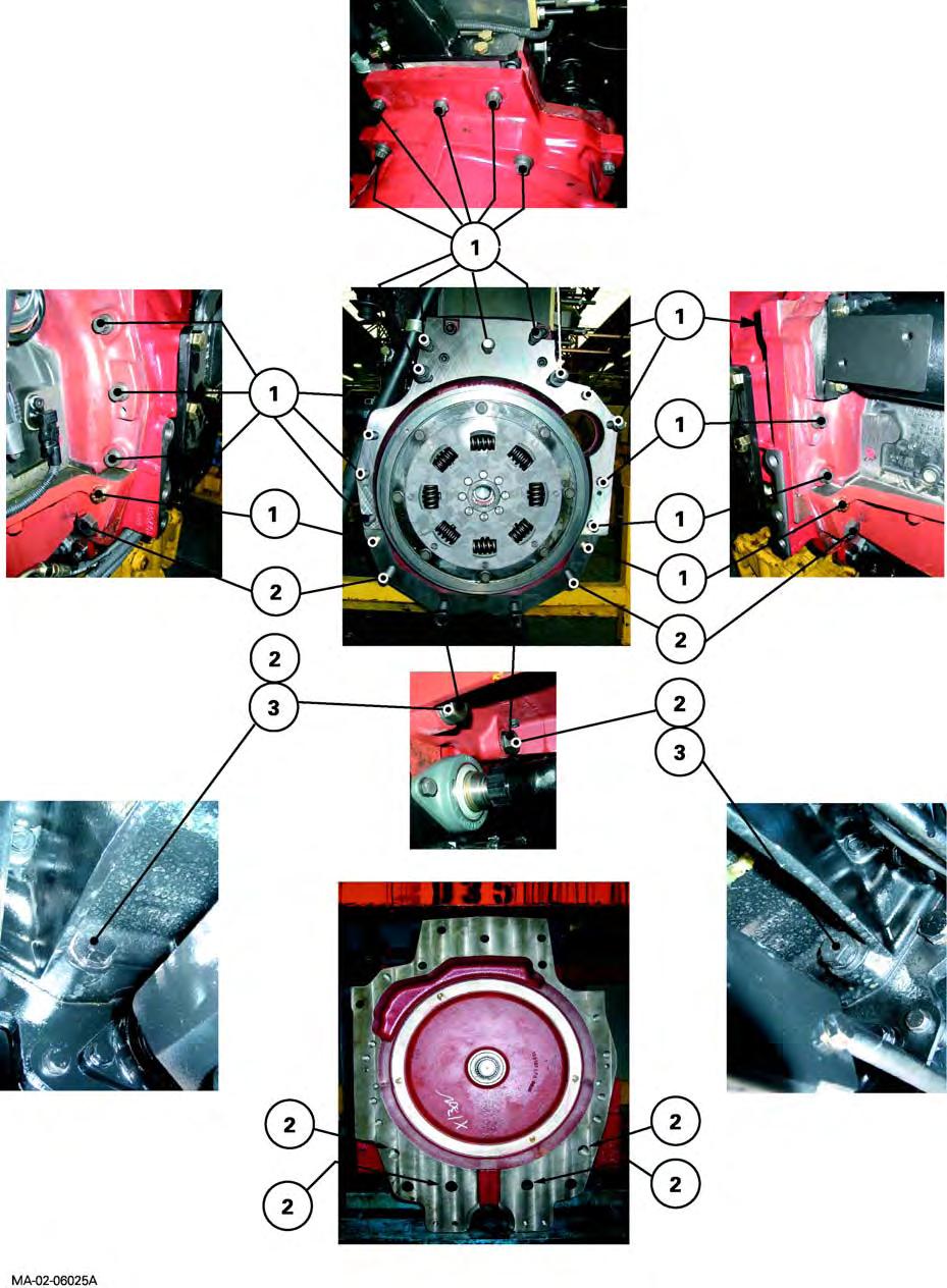
29. When the elements are joined, remove the guide studs (if fitted). Lightly smear the thread of the screws and nuts with Loctite 270 or equivalent and refit according to the marks made during disassembly. Tighten to the required torques (Fig.11)
-Screws (1): 115 Nm
-Screws (2): 280 Nm
-Screws (3): 735 Nm
-Nuts (4): 735 Nm
Fig. 10
Fig. 11
Perkins/GTA2520 engine separation
Final steps
NOTE: Final steps are not especially difficult. They should be carried out in the reverse order to preliminary steps. However, it will be necessary during reassembly to carry out the tightening torques, checks, adjustments and tests described below.
Tightening torques
As required:
•front cab screws (see chapter 12)
•screw (2) of connector (1) on main wiring harness (Fig.6 and Fig.12) 2.82 to 3.15 Nm
Topping-up
of coolant to the maximum level marked (radiator, expansion tank Fig.13).
Tests
-air conditioning system (if fitted—see chapter 12)
-cab suspension (if fitted—see chapter 12)
-all mechanical, hydraulic, electrical and electronic functions subject to operations
Checking tightness
-of hydraulic unions
-of bleed screw on control unit of suspended front axle (if fitted)
Fig. 12
Fig. 13
C
. Disassembling and reassembling (four-cylinder Perkins engine)
Implementation
30. Apply the handbrake.
31. Remove the side panels, prefilter (Perkins EEM engine) and bonnet.
Operations underneath the tractor
32. Take off the guard, shaft and differential lock supply pipe (4WD tractors).
Operations at the front of the tractor
33. Remove the front weights (if fitted).
34. Disconnect the batteries.
Tractors with…
Battery location
Perkins engine with mechanical injection in the grille compartment
Perkins EEM enginebehind the right-hand footstep
Location of batteries (Fig.14)
Fig. 14
CLICK HERE TO DOWNLOAD THE COMPLETE MANUAL
• Thank you very much for reading the preview of the manual.
• You can download the complete manual from: www.heydownloads.com by clicking the link below
• Please note: If there is no response to CLICKING the link, please download this PDF first and then click on it.
CLICK HERE TO DOWNLOAD THE
Perkins/GTA2520 engine separation
Operations on the right-hand side of the tractor
35. Take off the front right-hand mudguard.
36. Disconnect the flexible sleeve(1) (Fig.15) fitted to the suction port. If necessary, remove the vertical exhaust assembly (including support) (Fig.15).
37. Mark then disconnect: -the hose on the steering ram or on the spool valve (Orbitrol), depending on the tractor type -the lubricating hoses (running to and from the cooler) (Fig.16)
Operations on the left-hand side of the tractor
38. Take off the front left-hand mudguard.
39. Mark then disconnect: -the hose on the steering ram or on the spool valve (Orbitrol), depending on the tractor type -the fuel feed and return hoses on the engine. Immediately block the ports.
40. Disconnect the cables connected to the starter positive terminal (Fig.17).
Fig. 15
Fig. 16
Fig. 17
Operations under the cab
CAUTION: If the engine is still hot, allow it to cool.
NOTE: To work on heating hoses, it is not necessary to drain the engine block cooling circuit.
41. Pinch out each heating hose using a clamp fitted with plastic jaws (Fig.18).
Fig. 18
Perkins/GTA2520 engine separation
Operations on the engine
42. Mark and disconnect the heating hoses on the engine block and water pump. Block the ports immediately using suitable plugs.
43. Disconnect the negative cables on the block at the rear left-hand side of the engine (Fig.19).
44. If necessary, disconnect the connector(1) of the main wiring harness (Perkins EEM engine) (Fig.19).
45. Detach the air conditioning compressor, condenser and filter from their respective supports (if fitted).
Place the assembly beside the tractor without disconnecting the pipes and hoses (see chapter12).
NOTE: Carry out this action carefully.
Fig. 19
Operations at the front of the cab
46. Disconnect the connectors(2) and the ground terminals(1) on the left-hand side of the cab bulkhead (Fig.20).
Preparing for disassembly
47. Stop the front axle swinging by sliding a suitable wooden chock at each side of the support(1) (Fig.21).
48. Chock the rear wheels.
49. Install (Fig.22):
-a fixed stand at the front of the gearbox -a mobile stand at the rear of the engine
50. If necessary, separate the cab from the front rightand left-hand supports.
Gently lift the cab front using two straps fitted to the lateral handles.
Fix the cab in a raised position
Temporarily place a wooden chock between each support and the cab right- and left-hand attachments.
Fig. 20
Fig. 21
Fig. 22
Perkins/GTA2520 engine separation
Disassembly
51. Remove the screws attaching the engine to the gearbox (Fig.23). Mark their position and length.
52. Assisted by an operator, separate the assemblies (Fig.22).
Dimensions of the screws, studs and nuts
Screws
-M16 x 60 mm
-M22x80mm
MA-02-03002A
Fig. 23
Perkins/GTA2520 engine separation
Reassembly
Advice for use
Use guide studs to assist reassembly of the engine and gearbox.
53. Clean the mating face of the engine adapter plate and gearbox spacer.
54. Check for the presence of dowels(1) on the engine adapter plate (Fig.24).
55. Coat the input shaft splines of the gearbox lightly with AS767 grease or equivalent.
56. Screw two diametrically opposed guide studs to the engine adapter plate or to the gearbox spacer.
57. Connect the engine to the gearbox spacer.
Reminder
If necessary, remove the starter and slowly turn the flywheel ring gear using a suitable tool. This will ease engaging the vibration damper splines with those of the gearbox main shaft. If there is resistance, do not force it and find the cause of the problem.
58. When the two assemblies are joined, remove the guide studs (if fitted).
Lightly smear the thread of each of the screws(1) and (2) with Loctite270 or equivalent. Position them according to the marks made during disassembly.
Tighten (Fig.25):
-screws(1) to a torque of 120Nm -screws(2) to a torque of735Nm
Fig. 24
MA-02-03003A
Perkins/GTA2520 engine separation
Final steps
Note
Final steps are not especially difficult. They should be carried out in the reverse order to preliminary steps. However, it will be necessary during reassembly to carry out the tightening torques, adjustments and tests described below.
Tightening torques
As required:
-front cab screws (see chapter12)
-screw(2) of the connector(1) on the main harness (Perkins EEM engine) (Fig.19 and Fig.26) to a torque of 2.82–3.15Nm.
Topping-up
-of coolant to the maximum level marked on the radiator and expansion tank (Fig.27).
Tests
-air conditioning system (if fitted—see chapter12)
-cab suspension (if fitted—see chapter12)
-all mechanical, hydraulic, electrical and electronic functions subject to operations
Checking tightness
-of hydraulic unions
Fig. 26
Fig. 27
2B20 - Splitting – Sisu Engine / GBA10 Gearbox
CONTENTS
A.General
B.Disassembly.
C.Reassembly
Splitting – Sisu Engine / GBA10 Gearbox
Massey Ferguson 6400
CLICK HERE TO DOWNLOAD THE COMPLETE MANUAL
• Thank you very much for reading the preview of the manual.
• You can download the complete manual from: www.heydownloads.com by clicking the link below
• Please note: If there is no response to CLICKING the link, please download this PDF first and then click on it.
CLICK HERE TO DOWNLOAD THE
Splitting – Sisu Engine / GBA10 Gearbox
A . General
It is required to disassemble the tractor between the engine and the gearbox when access is necessary to carry out servicing on the following elements:
Engine interface
•Transmission damper
•Engine flywheel
•Engine adaptor plate
Gearbox interface
•Spacer, cover and sealing ring
•Internal hydraulic pipes
•Reverse shuttle and Dynashift
Remark
-This section presents a general disassembly procedure. Before and during disassembly, check that all connections have been properly separated between the fixed assembly and mobile assembly.
-The cab remains attached to the centre housing.
Splitting – Sisu Engine / GBA10 Gearbox
B . Disassembly
Preliminary operations
1. Put on the handbrake if necessary.
Remark
Putting on the handbrake is optional because the Park Lock mechanism (option) automatically immobilises the tractor when stationary.
2. Check that the suspended front axle (if fitted) is in low position and remove the control unit bleed screw (see chapter 9).
3. Remove the side panels either side of the engine and the bonnet (if necessary).
Servicing under the tractor
4. Remove the chassis reinforcements (if fitted, see chapter 2).
5. Remove the guard and the 4WD shafts.
Servicing at the front of the tractor
6. Remove the front weights (if fitted).
Servicing on the right-hand side of the tractor
7. Remove the footstep.
8. Disconnect and remove first the batteries and then the support.
9. Disconnect the flexible sleeve (1) (Fig.1) joined to the air filter, and remove the vertical exhaust assembly (including support Fig.2).
10. Mark then disconnect: -the cables (positive and negative) on the starter, -The front differential lock hose at both ends, -the hose on the steering ram, -the lubricating hoses (running to and from the cooler) (Fig.3).
Fig. 1
Fig. 2
Splitting – Sisu Engine / GBA10 Gearbox
Servicing on the left-hand side of the tractor
11. Remove the footstep.
12. Mark then disconnect: -the hose on the steering ram, -the hoses (pressure-return and LS) on the rigid pipes (Fig.4) of the suspended front axle (if fitted).
13. Mark and disconnect the fuel feed and return hoses on the engine (block ports immediately).
Remark
If the fuel tank is not removed it obstructs access to the engine attachment screw on the spacer, but does not prevent access. However, if there is a problem, remove the tank after marking and disconnecting it: -the gauge harness, -the vent hose on the tank.
Servicing under the cab
14. Mark, toe-in and disconnect the heating hoses, immediately blocking the ports.
Servicing the engine
15. Disconnect the connector (1) of the main wiring harness (Fig.5).
16. Separate the compressor, the condenser and the filter from their respective holders, and remove them carefully, without breaking the circuit (see chapter 12).
Remark -Work carefully.
Fig. 3
Fig. 4
Fig. 5
Splitting – Sisu Engine / GBA10 Gearbox
Servicing at the front of the cab
17. Disconnect the connectors (2) on the left-hand face of the fire wall (Fig.5).
18. If necessary, mark and disconnect the steering ram hoses on the spool valve (orbitrol) (Fig.6).
Preparing for disassembling
19. Stop the front axle oscillation (all versions) by sliding a suitable chock in either side of the support (1) (Fig.7).
20. Chock the rear wheels.
21. Install (Fig.9): -a fixed stand at the front of the gearbox, -a mobile stand at the back of the engine.
22. If necessary, separate the cab from the front rightand left-hand supports. Gently lift it using two straps fitted to the lateral handles. Place a block temporarily between the cab and the supports.
Disassembly
23. Remove the screws and nuts attaching the engine to the gearbox (Fig.8). Mark their lengths and positionings.
Fig. 6
Fig. 7
Fig. 8
Splitting – Sisu Engine / GBA10 Gearbox
Dimensions of the screws and nuts
Screws
-M16 x 60 mm
-M16 x 80 mm
-M16 x 110 mm
-M22 x 100 mm
-M22 x 120 mm
Nuts
-M22 x 2.5
24. With the help of an operator, separate the assemblies (Fig.9).
Reminder
When disassembling, check that connections (hoses, pipes and harnesses) are all disconnected.
Fig. 9
Splitting – Sisu Engine / GBA10 Gearbox
C . Reassembly
25. Clean the mating faces of the engine and the gearbox spacer.
26. Check the presence of locating pins (1) on the engine (Fig.10).
27. Lightly lubricate the splines of main shaft (1) (Fig.11) with grease (type GN + Molykote) or equivalent.
28. Grease the mating face of the spacer with Loctite 5206 or equivalent.
29. Screw two diametrically opposed guide studs on to the spacer.
30. Assemble the engine onto the gearbox spacer.
Reminder
-If necessary, manually turn the flywheel ring gear using the port provided to fit the starter, using a suitable tool. This will ease the engagement of the vibration damper splines with those of the main shaft. If there is resistance, do not force it and find the cause of the problem.
31. When the elements are assembled, remove the guide studs. Lightly grease the thread of the screws with Loctite 270 or equivalent and refit according to the marks made at disassembly. Carry out tightening torques (Fig.12).
-Screw (1): 240 - 320 Nm
-Screw (2): 630 - 840 Nm
-Nuts (3): 630 - 840 Nm
Fig. 10
Fig. 11
Splitting – Sisu Engine / GBA10 Gearbox
Massey Ferguson
Fig. 12
Splitting – Sisu Engine / GBA10 Gearbox
Final operations
Remarks
Final operations are quite simple and should therefore be carried out in the reverse order to preliminary operations. However, it will be necessary during reassembly to carry out the tightening torques, adjustments and tests described below.
Tightening torque
-Front cab attachment screw, if necessary. See chapter 12.
Topping-up
-of coolant to the maximum level marked (radiator, expansion tank. Fig.13).
Adjustments
-Chassis reinforcements (if fitted, see chapter 2).
Tests
-air conditioning system (if fitted – see chapter 12), -cab suspension (if fitted, see chapter 12),
-All mechanical, hydraulic, electrical and electronic functions concerned by servicing.
Checking tightness
-of hydraulic unions,
-of bleed screw on control unit of suspended front axle (if fitted).
Fig. 13
Splitting – Sisu Engine / GBA10 Gearbox
Massey Ferguson 6400
CLICK HERE TO DOWNLOAD THE COMPLETE MANUAL
• Thank you very much for reading the preview of the manual.
• You can download the complete manual from: www.heydownloads.com by clicking the link below
• Please note: If there is no response to CLICKING the link, please download this PDF first and then click on it.
CLICK HERE TO DOWNLOAD THE
2B21 - Splitting the Sisu engine/GTA1030
CONTENTS
A.General
B.Disassembly.
C.Reassembly
Massey Ferguson
Splitting the Sisu engine/GTA1030
A . General
Engine/GBA 10 gearbox splitting is to be carried out while maintaining the cab integral with the rear axle. This operation is needed when access to the following main elements is required for servicing:
• Gearbox interface: -spacer, cover and sealing ring, -hydraulic pipes internal to the spacer, -PowerShuttle and Dynashift.
IMPORTANT: This section presents a general disassembly procedure. Before and during disassembly, check that all connections have been properly separated between the fixed assembly and mobile assembly.
Splitting the Sisu engine/GTA1030
B . Disassembly
Preliminary operations
1. Apply the handbrake.
2. Check that the suspended front axle is in lowered position (if fitted).
3. Remove the bleed screw from the control unit (if fitted, see chapter 9).
4. Take off: -the side panels either side of the engine, -the bonnet.
Servicing under the tractor
5. Mark then disconnect the two ends of the hoses fixed to the 4WD transmission shaft guards (front and rear). Block their openings.
6. Remove the guards and 4WD transmission shaft.
Servicing at the front of the tractor
7. Remove the front weights (if fitted).
Servicing on the right-hand side of the tractor
8. Disconnect the batteries.
9. Take off: -the front mudguard; -the vertical exhaust assembly (including support) (Fig.1); -the side engine reinforcement; -the footstep (if necessary).
10. Disconnect the flexible particle suction sleeve (1) (Fig.2) between the air filter and the exhaust.
11. Mark and disconnect the starter electrical harness.
12. Remove the starter (if necessary).
MA-02-05125A
Fig. 1 1
MA-02-05126A
Fig. 2
Splitting the Sisu engine/GTA1030
Servicing on the left-hand side of the tractor
13. Remove the front mudguard.
14. Depending on the case:
-either move the fuel tank apart; -or, if necessary, remove the fuel tank in the following manner: -previously drain it partially of its fuel, -mark and disconnect its fuel gauge harness and vent hose, -Remove the tank.
15. Remove the side engine reinforcement.
16. Mark then disconnect:
-The lubrication pipes/hoses (1) located on the cab front firewall (Fig.3). These pipes/hoses allow for oil flowing between the cooler and the rear axle right-hand hydraulic cover;
-the rigid pipes (1) (Fig.4) (pressure, return and LS) to the suspended front axle (if fitted);
-the rigid pipes (2) (Fig.4) to the front linkage (if fitted).
-the gas-oil supply and return hoses on the engine. Block their openings.
MA-02-05127A
Fig. 3
MA-02-05113A
Fig. 4
Splitting the Sisu engine/GTA1030
Servicing under the cab
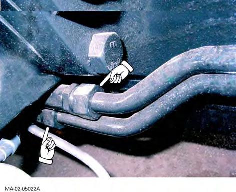
17. Mark the heating hoses (1) (Fig.5) at the base of the cab right-hand pillar. Pinch them both upstream and downstream of the square unions (2) (Fig.5) in order to keep fluid loss to a minimum.
18. DANGER: To perform the following operation, the engine must be cold. Opening the pressurised cooling circuit can lead to splashing of hot fluid and cause serious burns. If you need to perform servicing immediately (on a hot engine), ensure you are wearing appropriate protective clothing (goggles and gloves) and loosen the expansion tank plug progressively.
Disconnect the heating hoses. Block the openings.
Servicing the engine
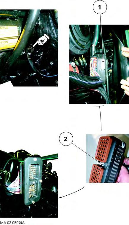
19. Mark and disconnect the ENG4 connector from the main harness at the rear of the engine (Fig.6).
20. Detach the air conditioning compressor, condenser and filter from their respective supports. Carefully keep them apart without opening the circuit (see chapter12).
IMPORTANT: If the air conditioning circuit should be open, see chapter12 before any action.
MA-02-05128A
Fig. 5
ENG4
MA-02-05129A
Fig. 6
Servicing at the front of the cab
Splitting the Sisu engine/GTA1030
21. Disconnect the ENG1 and ENG2 connectors located on the left-hand side of the cab firewall (Fig.7).
22. If necessary, mark and disconnect (Fig.8): -the hose on the steering unit (Orbitol) to the left-hand steering ram union. Block its opening; -the hose on the steering unit (Orbitol) to the right-hand steering ram union. Block its opening.
ENG2
ENG1
MA-02-05130A
Fig. 7
MA-02-05131A
Fig. 8
CLICK HERE TO DOWNLOAD THE COMPLETE MANUAL
• Thank you very much for reading the preview of the manual.
• You can download the complete manual from: www.heydownloads.com by clicking the link below
• Please note: If there is no response to CLICKING the link, please download this PDF first and then click on it.