USE THIS MANUAL
GENERAL INFORMATION
1.Range of repair work description
(1)Repair work is broadly divided to three processes of [Diagnosis], [Removal, replacement, disassebly/ assembly and check/ adjustment] and [Completion inspection].
(2)This manual describes the first process [Diagnosis] and the second process [Removal, replacement, disassebly/ assembly and check/ adjustment]. The third process [Completion inspection] is not included.
(3)This manual does not contain the information on the following works but they shall be implemented during actual work.
(a)Jacking and lifting
(b)Cleaning and washing of the removed part if necessary
(c)Visual check
2.Items to be prepared
(1)SST, service tools, grease/ others need to be prepared before work and they are listed as List of Items to be Prepared. The items that may be always kept at the general maintenance shop such as a tool stand, a jack, a rigid rack, however, are not listed.
(2)The tools or equipment listed in the List of Items to be Prepared except for SST are listed by way of example and any specific suppliers and item names/ item numbers are not designated.
3.Work procedure
(1)The block diagram is listed by section or title as needed.
(2)Nonreusable parts, grease applying points, precoat bolts and torques are indicated in the block diagram.
Front axle hub oil seal • Front axle hub whell snapring LH
Example: N*m (kgf*cm) : Specified torque • Non-reusable part
● Front axle hub bearing
Front disc brake dust cover Steering knuckle LH
• Cotter pin
49{500}
Front axle hub LH Tie rod end LH
Front disc
216{2200}
MP grease
(3)The torques, grease applying points, and nonreusable parts are indicated as key points of the procedure.
<CAUTION>
If the items above can be indicated with the illustration only, the block diagram describing the procedure is contained. Information on the torque and grease are also included in the illustration in that case.
(4)Procedural steps are shown for the items with the procedure only. The work part and content are indicated by the illustration and the text contains the detail work steps, the specified values and cautions.
(5)Some illustrations may be shared by similar vehicle types. Therefore, the details may be different from the actual vehicle.
Example:
Operation
CRANKSHAFT DAMPER INSTALLATION
Using the SST, hold the crankshaft damper and tighten the bolt.
Standard
Explanation: A detailed explanation of the operation method
4.Maintenance specified value
(1)The specified values and the limits are indicated by boldface in the text.
5.Definition of term
Specified value Indicates the tolerance for check and adjustment.
LimitIndicates the maximum and minimum values of the check and adjustment.
Reference value Indicates the specified value for the simple measurement method when there is no risk of occurrence of failure if the measurement method for acquiring the real specified value is extremely difficult.
<WARNING> The matters are included which may lead to trouble of the worker and others and may lead to trouble or accident if the contents are not observed.
<CAUTION> The matters to be especially paid attention and the work procedure that must not be implemented because the vehicle and/or components may be damaged if they are not observed.
<HINT>Supplemental information is separated from the text to facilitate the work.
6.SI unit
(1)The unit used in this manual is the SI unit (International System of Units), and then, the metric unit. (Example)
Specified value:T=28N*m {286kgf*cm}
Conversion coefficient table for SI unit
A163401
VEHICLE IDENTIFICATION AND SERIAL NUMBERS
1.Chassis number (1)The chassis number (vehicle identification number) is inscribed at the position shown in the diagram and on the nameplate.
A: Chassis number
B: Chassis number (GCC, UK & SOUTH AFRICA)
C: Name plate
D101843J01
D101844J01
Labeling position for Automatic transaxle: for Manual transaxle: Labeling position
2.Engine No. and transaxle No. (1)The engine No. is marked on the cylinder block.
A: 3SZ-VE, K3-VE
D101875J01
(2)Transaxle No. is attached onto the transaxle case.
CAUTIONS
1.SRS air bag and seat belt pretentioner
(1)Cautions for handling and work
(a)Handle the air bag and the pretentioner system with the correct procedure/method. If not, they may operate during work leading to the life-threatening accidents. In addition, they may not operate when necessary if repair is not performed correctly. Follow the correct procedure/method described in this manual when maintenance and check are implemented.
(2)Power supply removal
(a)Before starting the work, check the diagnostic trouble code, turn IG off, remove the battery minus terminal, and wait 90 seconds.
<WARNING>
The air bag/ the pretentioner system are equipped with a backup power supply. If the work is started before a lapse of 90 seconds after the battery minus terminal is removed, the air bag may be activated.
(3)General cautions
(a)Use the tester for the electrical check. But never measure the resistance.
<WARNING>
When the resistance is measured, the current of the tester may activate the air bag and the pretentioner, which is very dangerous.
(b)Observe the label instruction stating the cautions for the system periphery.
(c)Never dismantle the air bag and the pretentioner system.
(d)If the air bag and the pretentioner system are dropped or any crazing, dent, chip or other deformation is found, replace a new genuine part.
(e)Never use other vehicle's air bag and pretentioner part. Be sure to attach a new part when the part is replaced.
(f)Do not expose the air bag and the pretentioner system to high heat and fire.
(g)If the air bag and the pretentioner part do not operate at the time of impact, implement check with the diagnosis.
(h)Avoid grease, cleaner, oil and water attachment. If any of those is attached onto the part, immediately wipe it off with a dry cloth or suchlike.
(i)Avoid high temperature (atmospheric temperature 93×C and above [for the pretentioner, 80×C and above], humidity, and electrical noise for storing and handling the air bag and the pretentioner.
(4)Cautions for disposal of the air bag and the pretentioner (before activation)
(a)Never dispose the air bag and the pretentioner that have not operated (Always operate them using SST).
(b)Operate them in the safe and flat place of outdoors. Avoid the residential area.
(c)The operation sound is quite big. Keep everyone around informed in advance.
(d)Move away from the air bag/the pretentioner for 5 m or more using SST when they are activated.
(e)Static electricity may activate the air bag and the pretentioner. Touch the water pipe or steel frame with bare hands in advance to discharge the static.
(f)If the air bag is activated, avoid the deployment surface facing down.
<WARNING>
If the deployment surface faces down when the air bag is activated, the life-threatening accident may be caused.
(5)Cautions for disposal of the air bag and the pretentioner (after activation)
(a)Leave the activated air bag/pretentioner for 30 minutes or more after activation because the temperature of some parts is a few hundred ×C and above.
(b)Do not pour water or suchlike on the activated air bag and pretentioner.
(c)To handle the activated air bag and pretentioner, wear the dustproof glasses and gloves.
(d)Put the activated air bag and pretentioner in the solid transparent plastic bag. Seal the bag and dispose it.
(e)When the work is completed, always wash hands with water.
(6)Cautions in storing the air bag
(a)When the air bag is removed temporarily, for instance, during the work, keep the deployment surface up to store it.
<WARNING>
When the air bag is activated by some kind of cause, the deployment surface facing down may lead to the life-threatening accident.
(b)Avoid placing objects or other air bags on the air bag when storing it.
(7)Cautions for wire harness and connector
CLICK HERE TO DOWNLOAD THE COMPLETE MANUAL
• Thank you very much for reading the preview of the manual.
• You can download the complete manual from: www.heydownloads.com by clicking the link below
• Please note: If there is no response to CLICKING the link, please download this PDF first and then click on it.
CLICK HERE TO DOWNLOAD THE
(a)Wire harnesses and connectors are all yellow except for those kept in the engine room and special connectors are used. Handle them with care when disconnecting them.
(8)Measures for vehicles received impact by crash
(a)When the electrical welding machine is used, remove the air bag and the pretentioner before work.
(b)Remove the air bag computer assembly, the front air bag sensor, the side air bag sensor assembly, and the side air bag sensor assembly No. 2 before work if impact may be impressed on them.
(c)Avoid exposing the air bag computer assembly, the front air bag sensor, the side air bag sensor assembly, and the side air bag sensor assembly No. 2 to high temperature.
(d)Some parts of the air bag and the pretentioner reach a few hundred ×C and above during activation. Make sure that the peripheral wire harnesses and connectors have no damage and melting part.
2.Basic items
(1)Points on work
1Appearance
>Always put on a clean engineer wear.
>Wear a cap and protective shoes.
2Vehicle protection>Place a grille cover, a fender cover, seat covers and a floor mat before work.
>Use sprags to fix a vehicle.
3Safety work
4 Preparation for tools and measuring instruments
5Removal/ Disassembly/ Assembly
>When the work is performed by two or more persons, check each other's safety.
>In case of the work with the engine on, pay attention to ventilation.
>Be careful with burn and injury in case of working on the part that may become hot, the rotating part, the sliding part, and the vibrating part.
>When the vehicle is jacked up, support it at the specified position with a rigid rack.
>When the vehicle is lifted up, use the safety device.
>Prepare a tool stand, SST, measuring instruments, grease, waste and the part for replacement before starting to work.
>Understand the phenomenon of the failure thoroughly and diagnose for efficient work.
>Check the attaching condition, deformation and damage before removing the part.
>If the construction is complicated, take a note and put the dowel mark to prevent adverse influence on the function.
>Clean, wash, and check the removed part as needed before reattaching. 3
6Removed part
(2)Gasket
>Organize the removed parts avoiding mixing them up or making them dirty.
>Replace nonreusable parts such as gaskets, O-rings, and self-lock nuts with new parts according to the instruction in the text.
>Organize the parts replaced in the box to show the customer.
(a)A gasket must not be reused. Always replace it with a new one.
(b)Use a sealing agent for the gasket, if necessary, to prevent leakage.
(3)Bolts, nuts, and screws
(a)Check the torque for the bolts, nuts, and screws and always use a torque wrench.
(4)Fuse replacement
(a)When the fuse is replaced, replace it with the fuse with the same capacity. If there is no choice to use a fuse with the different capacity, use the fuse with the capacity lower than the specified ampere.
BE01367J01
IllustrationSymbol
Part Name Abbreviation Fuse
Medium current fuse
High current fuse
Fusible link
Circuit breaker
Fusible link assembly
(5)Clip
(a)When the fitting is shaken at the clip position and the tab position, be sure to use the protective tape to prevent the vehicle from being damaged.
(b)General clip removal for the body parts is shown in the diagram.
<HINT>
>If the clip is damaged during the work, be sure to replace it with a new one.
>The dotted triangle in the illustration indicates a clip and the dotted circle indicates a tab.
D100151J02
Centering bolt
(6)Cautions for fitting adjustment
(a)If a centering bolt is used at the hinge of the bonnet or door, replace it with the supplied bolt before fitting adjustment.
D032152J01
(7)Jack-up, jack-down, and support of the vehicle
(a)If the vehicle is jacked up or down and supported, be sure to observe the cautions (See page 01-16 for the jack, the rigid rack, and the support position of the lift).
(8)Vacuum hose removal and installation
(a)To draw the vacuum hose out, hold the hose end.
D025063J01
(b)When the vacuum hose is removed, use a tag to indicate where the hose is connected.
(c)When the vacuum gage is used, do not connect the hose if the connector is too big. Use the slightly smaller adapter for adjustment. If the hose is stretched, the air may be leaked.
D025064J01
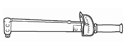
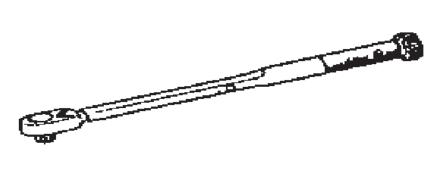
(9)Tightening tool
(a)Use the torque wrench shown in the table below (or equivalent) for torque management described above. Select the best-suited torque wrench, together with an extension tool (such as an extension bar) in accordance with the work space.
Torque wrench
Product namePart No.Torque range
SF 1.5 N6.3 sq (0.2-1.5 N*m)
SF6N6.3 sq (0.6-6 N*m)
Plate-type torque wrench
Ratchet preset type Torque wrench
F23N9.5 sq (3-23 N*m)
F46N9.5 sq (5-46 N*m)
F92N12.7 sq (10-92 N*m)
F130N12.7 sq (20-130 N*m)
F190N12.7 sq (30-190 N*m)
QL25N-MH9.5 sq (5-25 N*m)
QL50N-MH9.5 sq (10-50 N*m)
QL100N-MH12.7 sq (20-100 N*m)
QL140N-MH12.7 sq (30-140 N*m)
QL200N-MH12.7 sq (40-200 N*m)
Extension bar
BE3-0309.5 sq (30 mm)
BE3-0509.5 sq (50 mm)
BE3-0759.5 sq (75 mm)
BE3-1009.5 sq (100 mm)
BE3-1509.5 sq (150 mm)
BE3-2709.5 sq (270 mm)
BE4-07512.7 sq (75 mm)
BE4-15012.7 sq (150 mm)
BE4-27012.7 sq (270 mm)
BE4-60012.7 sq (600 mm)
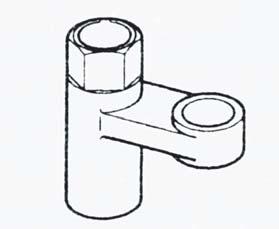
(b)The text contains the specified torque only. If the SST or extension tool is used, determine the torque wrench reading by the calculation formula.
D101545J02
(c)When the SST or tool is combined to the torque wrench to extend the total length and tighten, if the torque wrench reading reaches the specified torque value, the actual torque becomes excessive.
(d)Calculation formula T'=T × B/(A + B)
SymbolMeaningUnit
T'Torque wrench reading[N*m {kgf*cm}]
TSpecified torque[N*m {kgf*cm}]
ASST or tool length[cm]
BTorque wrench length[cm]
3.Electrical system
(1)Battery terminal removal
Loosen the bolt
D001555J01
(a)In case of the work for the electrical system, remove the battery minus terminal in advance to avoid burnout caused by short circuit.
(b)If the battery terminal is removed, turn off the ignition switch and the lighting switch and loosen the nut of the terminal to avoid shaking it.
(c)If the battery terminal is disconnected, the memory such as a clock and diagnosis will be erased. Check the content in advance.
D001556J01
(d)To attach the battery terminal, connect the plus terminal first and then the terminal wire so that it is kept in the range shown in the diagram, and tighten it with the specified torque.
Specified value:T=6.4N*m {65kgf*cm}
4.Removal of parts in fuel system
(1)Removal work area for the parts in fuel system
(e)To attach the battery minus terminal, connect it so that the terminal wire is kept in the range shown in the diagram, and tighten it with the specified torque.
Specified value:T=6.4N*m {65kgf*cm}
(2)Handling of electronic components
(a)Do not open the ECU cover or the case (Touching the IC terminal may damage the IC due to static electricity).
(b)Avoid giving impact on the electronic components such as computers, sensors and relays. If such components are dropped, replace them.
(c)Do not expose the electronic components to high temperature/ high humidity.
(d)If the engine is cleaned with steam, pay attention not to put water directly on the electronic parts, air filter and emission related parts.
(e)Do not touch the connector terminals since failure due to deformation and static electricity may occur.
(f)Never remove and attach the temperature switch and the temperature sensor using the impact wrench.
(a)Work in the well-ventilated place without a welding machine, grinder, drill, electric motor and any fires such as a stove around.
(b)Avoid working at or near the pit where evaporated fuel may be filled.
(2)Removal of parts in fuel system
(a)Prepare an extinguisher before the work is started.
(b)For static prevention, water under foot as much as the worker does not slip as well as ground the fuel changer, the vehicle, and fuel tank.
(c)Do not use electrical equipment such as an electric pump and a working lamp since sparks may fly and the equipment may become very hot.
(d)Do not use an iron hammer since sparks may fly during the work.
(e)Handle the waste to which the fuel is attached separately.
5.Removal of engine air intake system parts
(1)If metal pieces get in the air intake path, the engine is adversely affected.
(2)When the air intake parts in the air intake system are removed, cover the removed parts and the opening on the engine side with a clean waste cloth or a gum tape.
(3)When the air intake parts are attached, make sure that foreign particles such as metal pieces do not get in.
6.Handling of hose/ hose clamp
(1)Before removing the hose, check the insertion depth and the clamp position so that it can be reattached properly.
(2)If the clamp is deformed or degraded, replace it with a new one.
(3)If the hose is reused, adjust the clamp at the clamp mark left on the hose and attach it.
(4)For the flat spring clamp, impress the camp in the direction of the arrow to fit it in after attachment.
(5)When the hose is disconnected, use the SST (a plug set and a hose) to cover the hose and prevent leakage of the grease or the cooling water.
<CAUTION>
Check if foreign particles such as stains, dust, and iron powder are not attached onto the SST before use. If so, be sure to clean them.
SST09258-00030
7.Radio equipment installation
(1)Attach the antenna as far away from the vehicle electronic system such as computers and sensors as possible.
(2)Attach the antenna cord at least 20 cm away from the vehicle electronic system such as computers and sensors.
(3)Do not bind the antenna cord with other wires. Place the antenna cord as far away from other wires as possible.
(4)For retrofitted items, attach them according to the individual installation procedures.
(5)Do not attach high-power mobile communication equipment.
Do Not Illuminate More Than 3 Minutes
8.Head lamp check and maintenance
(1)If the cover is used while the head lamp is lit, do not implement maintenance for 3 minutes or more.
<CAUTION>
The outer lens used for the head lamp is plastic and it may be deformed if the check and maintenance takes a long time.
Clamp
When drum tester is used:
9.Traction control (TRC) and VSC (Vehicle Stability Control) (2WD vehicle)
(1)Cautions when the two-wheel drum tester is used
(a)If the two-wheel drum tester, such as a speed meter tester, a speed meter tester and brake tester combined machine, and a chassis dynamometer, is used, be sure to turn on the traction control switch (TRC OFF switch) to prohibit the TRC control before measure.
<WARNING>
When the drum tester is in use, the vehicle may dash out from the tester due to the TRC operation.
<CAUTION>
>Check if the TRC operation is disabled with illumination of the slip indicator lamp in the combination meter.
>Fix the vehicle with a lock chain for safety work.
<HINT>
See Cautions for VEHICLE STABILITY CONTROL SYSTEMCautions when the drum tester is used for how to disable the TRC control.
(b)When the check by the drum tester is completed, be sure to cancel the operation prohibition mode.
<WARNING>
Always cancel the operation prohibition mode after the check is finished. Do not drive the vehicle with the operation prohibited condition.
(2)Cautions for VSC related work
(a)Do not remove the VSC related parts unless otherwise necessary because removal may cause incomplete adjustment.
(b)When the work related the VSC is implemented, be sure to perform preparation before work and check after completion according to the instruction of the manual.
10.Cautions for check and maintenance of the full-time 4WD vehicle
<CAUTION>
The tester with load setting system for two wheels only (model with the power absorption system for two wheels only: a two-wheel chassis dynamometer, two-wheel chassis dynamometer and speed meter tester, a brake tester combined machine) can not be used.
D101847J01
(1)Speed meter tester measurement procedure
<CAUTION>
>Check the front wheel.
>Avoid rapid starting and sudden acceleration.
>The maximum speed shall be 60 km/h or less (50 km/h or less when the free roller is used).
>The vehicle shall be run within 1 minute.
>If the procedure below is not observed, function deterioration of the 4WD, failure of the drive system parts, and dash-out of the vehicle are possible. Always follow the procedure described below.
(a)Place the front wheels on the roller.
(b)Free the rear wheels with a free roller or a rigid rack.
(c)Use the lock chain to fix the vehicle.
(d)Start the engine and gradually increase the vehicle speed with D range to measure the tester.
(e)After measurement, use the brake to decelerate gradually and stop the vehicle.
11.Brake tester measurement procedure
<CAUTION>
>A tester with load setting system can not be used.
>A high-speed brake tester can not be used.
(1)Place the wheels of the vehicle to be measured (front or rear wheels) on the roller.
(2)Change the shift position to neutral.
(3)Drive the roller of the tester to measure.
<HINT>
When the drag force exceeds 10% of the axle load, jack both right and left axles up to check the wheel rotation. If no failure is found, it is caused only by the viscous torque of the viscous coupling and it is not abnormal.
12.Cautions in towing a 2WD vehicle
(1)Tow the vehicle with front wheels or all four wheels lifted. If the vehicle is towed with four wheels road held, it shall be pulled forward within the distance of 50 km at the pulling speed of 30 km/h or less.
<WARNING>
If the vehicle is towed exceeding these speed and distance or backward, the transaxle is adversely affected and may be damaged.
CLICK HERE TO DOWNLOAD THE COMPLETE MANUAL
• Thank you very much for reading the preview of the manual.
• You can download the complete manual from: www.heydownloads.com by clicking the link below
• Please note: If there is no response to CLICKING the link, please download this PDF first and then click on it.
CLICK HERE TO DOWNLOAD THE
Car carrier
13.Cautions in towing a 4WD vehicle
(1)Tow the vehicle with four wheels road held or lifted. If the vehicle is towed with four wheels road held, it shall be pulled forward within the distance of 50 km at the pulling speed of 30 km/h or less.
<CAUTION>
If the vehicle is towed exceeding these speed and distance or backward, the transaxle is adversely affected and may be damaged.
(2)Tow the vehicle with both the front and rear wheels lifted if it is lifted to tow. If there is failure in the running system and the drive system, carry the vehicle with four wheels lifted.
<CAUTION>
Towing the vehicle with only either the front or rear wheels lifted may burn the transaxle or make the wheels protrude from the tow truck.
(3)Tow the vehicle following one of the methods shown in the diagram.
Tow truck (raising all four wheels)
Tow truck (All tires in contact with the road)
Towing speed:Less than 30km/h
Towing distance:Less than 50km/h
Direction to tow
<CAUTION>
>If there is failure in the chassis and the drive train of the vehicle, use a carrier car.
>Always use the towing method shown in the diagram.
Parking brake and shift lever state during towing
Towing methodParking brake
Transmission Shift lever position
Carrier carBrake pulledAny position is OK.
Break down lorry (four wheels lifted)Brake pulledAny position is OK.
Break down lorry (four wheels road-held)Brake releasedNeutral
14.Vehicle with a catalytic converter
(1)If a large amount of unburned gasoline flows in the converter, the catalyst will be damaged. To prevent this, observe the followings.
(a)Use unleaded gasoline only.
(b)If spark check of the spark plug is necessary, remove the connector of the injector to stop the injection.
(c)To measure the compression pressure of the engine, remove the connector of the injector to stop the injection.
D101848
D101349J01
(d)Do not operate the engine with the fuel tank almost empty. If the engine is operated under such condition, misfire occurs and excessive load may be applied to the converter.
VEHICLE LIFT AND SUPPORT LOCATIONS
1.Cautions for the vehicle condition when it is lifted up
(1)The vehicle must be almost empty. Do not jack and lift the vehicle up with heavy objects loaded.
(2)When the heavy objects such as an engine and a mission are removed, the gravity center of the vehicle will be shifted. Therefore, mount then so that the balance weight does not turn over or hold the jack support position with a mission jack or suchlike.
(3)Be sure to support the specified position with the jack, rigid rack, holding block and attachment.
(4)Never jack or lift up the vehicle exceeding the jack or lift capacity.
2.Support position when the vehicle is lifted up
From front cutout of rigid rack support position
428 mm
4WD: FF: for both RHD and LHD 472 mm
Do not jack up in the locations
From front cutout of rigid rack support position
Do not jack up in the locations
Position of garage jack support
Position of rigid rack support Center of gravity (That of the average vehicle without load)
3.Cautions when the jack and the rigid rack are used (1)Be sure to work in the flat area using sprags.
D101173J05
(2)Use the rigid rack with a rubber attachment as shown in the diagram.
(3)Be sure that the jack supports at the specified position with the center of the jack dish.
<CAUTION>
Avoid putting the garage jack onto the oil pan.
(4)Be sure that the rigid rack supports the specified position.
(5)If the front wheels are jacked up, release the parking brake and place the sprags at the back of the rear wheels. If the rear wheels are jacked up, place the sprags at the front of the front wheels.
(6)If only either the front or rear wheels are jacked up, place the sprags at both the front and back of the wheels contacting the ground.
<HINT>
Do not work or leave the vehicle supported with a jack only. Always use the rigid rack.
(7)When the vehicle which is jacked up with only the front wheels is jacked down, release the parking brake and place the sprags only at the front of the rear wheels. When the vehicle which is jacked up with only the rear wheels is jacked down, place the sprags only at the back of the front wheels.
4.Cautions when the plate lift is used
(1)Operate the lift safely according to the operation manual of the lift.
<CAUTION>
If the lift support position is largely away from the vehicle center, the vehicle becomes significantly unstable or the under cover may be damaged.
(2)Use the plate lift attachment.
(3)When the vehicle is lifted up using the plate lift, make sure that the vehicle center comes in the vehicle center tolerance of the lift support.
<CAUTION>
If the vehicle center is out of the tolerance, the vehicle may shake when it is lifted up and down.
<HINT>
If the tolerance of the vehicle center of gravity is unknown, ask the manufacturer of the lift. Gum attachment
(4)Be sure to drive the vehicle in to the specified position.
Vehicle setting position in the horizontal directionDrive the vehicle in the center of the lift.
Vehicle setting position in the anteroposterior direction
>Align the end of the plate cushion rubber to the bottom end of the attachment (A and C).
>Adjust and align the top end of the attachment to the front notch of the rigid rack support position on the front side, avoiding contacting the rocker molding (B).
(5)Lift the vehicle until the tire is slightly lifted up and check if the vehicle is stable.
5.Cautions when the swing arm lift is used
(1)Operate the lift safely according to the operation manual of the lift.
(2)Use the support with rubber attachment as shown in the diagram.
(3)Drive the vehicle in so that the lift center is as close to the vehicle center of gravity as possible (L
as possible).
D101351J02
Swing arm lift:
D101849J01
(4)Avoiding contacting the rocker molding, adjust the lift support height so that the vehicle is leveled. Then, fit the rigid rack support position in the groove of the lift support.
(5)Be sure to lock the swing arm during the work.
(6)Lift the vehicle until the tire is slightly lifted up and check if the vehicle is stable.
6.Cautions when the four-post lift and the drive-on type lift are used
(1)Work safely according to the operation manual of the lift.
(2)Do not damage the tires and wheels with the free wheel beam.
(3)Use sprags to fix a vehicle.
NEW DIAGNOSIS SYSTEM
SIL Diagnostic Communication
(Communication Speed 10.4 kbps or 9.6 kpbs)
CAN Diagnostic Communication (Communication Speed 500 kbps)
Diagnostic Tool DS-II
ECU Communicating
DS-II
Each Diagnostic Comunication Connection
D101871
1.Overview
(1)The new diagnosis system is a new failure diagnosis system conforming to the onboard electronics system that has become sophisticated,complicated. The function of this system can be used by the diagnostic tool DS-II.
2.Function of the diagnostic tool DS-II
(1)The diagnosis tool DS-II compliant with this new diagnosis system contains the functions shown in the table below.
Function Overview
Bus checkCAN bus diagnosis function
CARB modeIndividual functions compliant with ISO 15031-5
DTC check Function to display the diagnostic trouble code and the freeze data saved in memory at occurrence of failure
Diagnostic functions
Data listECU data monitoring function using values and graphs.
Active testFunction to drive the actuator forcibly.
UtilitiesWork support function necessary at replacement of the ECU and the actuator
Saved data playback functionsFunction to play back the saved data after the failure is diagnosed.
Measurement functionsVoltage measurement and oscilloscope function
3.Diagnosis communication enabled computer/ sensor
Computer/ sensor name
Diagnostic trouble code read (Normal mode)
Diagnostic trouble code read (Check mode, test mode)
Freeze frame data read (Computer data at occurrence of failure)
Transponder
*: Freeze data when the system is operated is readable.
Data monitor read and save/display Active test
Diagnosis communication line
Diagnosis tool
4.How to use the diagnostic tool DS-II
(1)Connection to the vehicle
(a)Connect the DLC (data link connector) installed around the feet of the driver.
(2)How to use the diagnostic tool DS-II
(a)When the power switch of the DS-II is turned on, the menu screen is displayed.
(b)Select [OBD] and select [Next] after selecting all vehicle information, and the [System Select] screen will be displayed.
(c)Select any item to be implemented. Then, proceed afterward interacting with the screen.
5.Diagnosis connector
(1)Along with adoption of the new diagnosis system, the function is put together at the DLC (installed at the bottom of instrument panel of the driver seat).
(2)Names and functions of the DLC terminals
Terminal nameFunction
BATBattery power
CANLCAN communication LO
ECU-TECU-T check terminal
EFI-TEFI-T check terminal
REVEngine revolution signal
SIODiagnosis communication with each computer
CANHCAN communication HI
ESignal earth
EBody earth
EPS-TSEPS-TS check terminal
D101342J01
D101872
6.Handling at occurrence of errors
<CAUTION>
If the power indicator of DS-II is not lit or if names of all diagnosis communication enabled and diagnosis CAN communication enabled systems are not displayed when the menu is displayed, implement the following checks and repair the failure.
(1)DS-II power indicator is not lit
(a)Connect the DS-II to the other vehicle and start the DS-II.
Operational statusFailure pointCheck point
When the DS-II power indicator is lit red or green
When the DS-II power indicator is not lit
Vehicle side
1.Voltage check of the DLC BAT terminal
2.Conductivity check between the DLC E teminal and the body earth
(2)If the system diagnosis is pressed in the diagnosis menu, the names of all diagnosis communication enabled and diagnosis CAN communication enabled system are not displayed.
(a)Turn off the IG switch and DS-II power and then start the DS-II again.
(b)Select [OBD] and check the status when the [System Select] screen is displayed after inputting all vehicle information.
Operational statusFailure pointCheck point
All system names are not displayed.
The names of the diagnosis communication enabled system are not displayed.
The names of the diagnosis CAN communication enabled system are not displayed.
Vehicle side
One diagnosis communication enabled system name is not displayed.
Vehicle side
1.Conductivity check between SIO terminal of the DLC communication line and the junction
2.Short circuit of +B and earth between SIO terminal of the DLC communication line and the junction
Correct the CAN communication following the steps after Step 4 [DLC check (CANH-CANL)] in CAN communication troubleshooting.
1.Conductivity check between SIO terminal of the DLC communication line of the nondisplay ECU and the junction
Vehicle side
One diagnosis CAN communication enabled system name is not displayed.
Vehicle side
2.Short circuit of +B and earth between SIO terminal of the DLC communication line of the nondisplay ECU and the junction
3.Nondisplay ECU+B and earth check
4.Nondisplay ECU replacement
Correct the CAN communication following the steps after Step 3 [Diagnostic Trouble Code Check] in CAN communication troubleshooting.
CLICK HERE TO DOWNLOAD THE COMPLETE MANUAL
• Thank you very much for reading the preview of the manual.
• You can download the complete manual from: www.heydownloads.com by clicking the link below
• Please note: If there is no response to CLICKING the link, please download this PDF first and then click on it.
CLICK HERE TO DOWNLOAD THE
HOW TO PROCEED WITH TROUBLESHOOTING
<HINT>
Troubleshoot according to the diagnosis procedure described below. Only the basic procedure is described here. For details, the most efficient method by circuit is described for the system in each section. Check the troubleshooting procedure before starting to troubleshoot the appropriate circuit.
(1)Ask the customer the state and condition where the failure occurred and prepare the inquiry sheet accordingly.
(1)Check the battery voltage using the tester.
Specified value: 11 - 14 V (at engine stop)
(2)Check all the parts that can be checked visually: blown fuse, wire harness disconnection, short circuit, badly connected connector, etc.
(3)Check the phenomenon and status of the failure and check the diagnostic trouble code according to the applicable chart.
With the diagnostic trouble code: To each list of diagnostic trouble code
Without the diagnostic trouble code: To List by Symptom
(1)Check and understand each setting status of the vehicle before the repair because some data in the memory may be erased or some settings may be initialized by disconnecting the battery minus terminal.
<HINT>
Setting when the part is replaced/ removed (See page 03-8)
(1)Check if the circuit in the system is checked or which part to be checked using the list of diagnostic trouble codes or list by symptom.
(1)Repair the failed system or part according to the instruction of Step 5.
7 CHECK TEST 8 RESTORATION OF THE VEHICLE STATUS
(1)Check if the failure is eliminated after the repair is completed. (If the failure reappears, implement the check test in the same environment with the same status where the failure originally occurred.
(2)If the diagnostic trouble code is input for the failure, check the diagnosis result.
(1)Return each setting to the vehicle condition checked at Step 4. <HINT>
If there are any settings which can not be returned to the original settings, explain that to the customer.
CUSTOMER PROBLEM ANALYSIS
1.Eliminate any preconceived notion during troubleshooting to check the failure phenomenon correctly and assess the failure properly. It is very important to ask the customer the condition where the failure occurred to check the failure phenomenon.
2.The following five items are important for analysis. The past failure that seems unrelated and the repair history may be useful. It is essential for troubleshooting to collect such information as much as possible and understand the relationship to the current failure precisely. The inquiry sheet is contained in the diagnosis section of each system.
>What - vehicle model, system name
>When - date and time, frequency
>Where - course condition
>Condition - running status, weather
>How it happened - failure phenomenon
<HINT>
Shown below is an example of the inquiry sheet.
Model
VIN
Accessories
Previous vehicle
Engine Problem Diagnosis Check Sheet
Date vehicle brought in
Date registered
Date problem first occured
Customer profile/characteristics
Description of symptoms
Service history No/Yes (__times)
Registration No. Odometer reading km
Main region/purpose of travel
Warning light illumination Off/On ( )
System Conditions
Speed problem first occured( )km/h
Shift position ( ) range
Starting off Immediately after start off ( ) min after start After ( )min driving Cold Warm Idling Others ( )
Check Results Additional Items
DTC Inspection
Malfunction Indicator Lamp (MIL) OffOn
Inspection Results
Problem details
Driving Conditions Increasing speed Decreasing speed Braking Turning Stopped Not related Others ( )
Road Conditions
Starting off Cruising
Level
Uphill
Downhill
Dry paved road Wet paved road Ambient air temperature ( ) Weather ( ) Unpaved/rough road Snowy/icy road Uneven, manholes etc.
Others ( )
Accelerator opening ( )% Others Problem Frequency Always One time only Sometimes (_)times a day (_)times a week (_)times a month
Normal Code(s) Malfunction code(s)(all noted)
Driving conditions and location when problem first occured and reoccured
Fuel pressure when engine stopped
Fuel pressure 1 min. after engine stopped
Reoccurence conditions Always OccasionalOnce problem occurs, it continues Does not reoccur
Dealer Name Office Person in charge Technician
SYMPTOM CONFIRMATION AND DIAGNOSTIC TROUBLE CODE
<HINT>
The diagnosis system contains various functions. If a failure occurs in the signal circuit to the ECU, it is saved as a code in the ECU memory and the code is output as a diagnostic trouble code during troubleshooting. The diagnosis function is incorporated in the following system to narrow down the range where the failure occurs quickly and troubleshoot efficiently utilizing this diagnosis function.
System [ECU]
Diagnostic trouble code Check (Normal mode)
DS-II
Diagnostic trouble code Check (Normal mode)
DLC (ECU-T ↔ E shortcircuit)
Diagnostic trouble code Check (Test mode) (Check mode)
EFI system (3SZ-VE)[engine ECU]OO-
EFI system (K3-VE) [engine ECU]OO-
Automatic transaxle system [AT ECU]OO-
Anti-lock brake system [skid control computer]OOO
Vehicle stability control system [skid control computer]OOO
Power steering system [power steering computer assembly]OOO
SRS air bag system [air bag ECU]OOO*
Engine immobilizer system [Transponder key ECU]OO-
LIN communication system---
CAN communication systemOO-
*: Check mode
It is very important for the diagnostic trouble code check to determine if the failure indicated by the diagnostic trouble code is ongoing or it occurred in the past but is now returned to normal. In addition, it is necessary to check if the failure indicated by the diagnostic trouble code is directly related to the failure phenomenon through the failure phenomenon check. For this reason, it is required to check the diagnostic trouble code before and after checking the phenomenon in order to evaluate the current status. Failing to perform this may lead to unnecessary troubleshooting regardless of the normal operation system and makes it difficult to find where the failure is, ending up with unrelated and unnecessary repair. Therefore, it is important to always check the diagnostic trouble code following the correct work procedure.
<HINT>
>The flow chart below shows the troubleshooting procedure using the diagnostic trouble code.
>This flow chart shows how to use the diagnostic trouble code efficiently. It also shows how to proceed to troubleshooting using the diagnostic trouble code or the list of failure phenomena by checking the result thoroughly.
1 FAILURE INDICATION (INQUIRY)
2 DIAGNOSTIC TROUBLE CODE CHECK
<CAUTION>
Be sure to check all diagnostic trouble codes.
A
Can not read from all the connection ECU
BWithout the diagnostic trouble code
CWith the diagnostic trouble code
TO STEP 7
TO STEP 8
SAVING THE DIAGNOSTIC TROUBLE CODE AND THE FREEZE FRAME DATA A
(1)Save the output diagnostic trouble code and freeze frame data.
<CAUTION>
Do not erase the code and the data before saving them. If they are erased before saved, all of the diagnostic trouble code, freeze frame data, and history data will be erased.
<HINT>
>If several codes are output, find out the main cause from all diagnostic trouble codes.
>Use the input timing estimated data (data monitor) for EFI, AT, and ABS.
>Some diagnostic trouble codes are output even if it is not failure (sunlight sensor for air conditioner, non-learning after battery clear).
Except for the diagnostic trouble code for communication
The diagnostic trouble code for communication only
The diagnostic trouble code for communication and other diagnostic trouble codes
TO STEP 5
BUS (COMMUNICATION WIRE) FAILURE (SEE THE CAN COMMUNICATION SYSTEM AND THE LIN COMMUNICATION SYSTEM.)
4 DETERMINING FAILURE CAUSE
(1)Determine if the main cause is the part or the bus (communication wire) according to all diagnostic trouble codes.
<HINT>
The diagnostic trouble code for communication may be output simultaneously by part failure.
ABus (communication wire) failure
BPart failure
TROUBLESHOOTING OF THE BUS (COMMUNICATION WIRE) FAILURE (SEE THE CAN COMMUNICATION SYSTEM AND THE LIN COMMUNICATION SYSTEM.)
5 DIAGNOSTIC TROUBLE CODE AND FREEZE FRAME DATA ERASE
6 RUNNING TEST AND DIAGNOSTIC TROUBLE CODE CHECK
AWith the diagnostic trouble code
BWithout the diagnostic trouble code
TROUBLESHOOTING ACCORDING TO THE FLOW BY DIAGNOSTIC TROUBLE CODE
SIMULATION TEST USING THE SIMULATION METHOD OF THE FAILURE PHENOMENON
7 CONNECT THE DS-II TO OTHER VEHICLE AND CHECK THE DIAGNOSTIC TROUBLE CODE
Can not read when the DS-II is connected to other vehicle as well. BNormal in case of other vehicle
DS-II FAILURE (See page 01-21 FOR HANDLING WHEN DS-II FAILURE OCCURRED.)
BUS (COMMUNICATION WIRE) FAILURE (SEE THE CAN COMMUNICATION SYSTEM AND THE LIN COMMUNICATION SYSTEM.)
8 FAILURE PHENOMENON CHECK
THE SYSTEM IS NORMAL
(1)Use the inquiry result and the ECU data monitor to determine if the customer indication is actual failure.
TROUBLESHOOTING ACCORDING TO THE FLOW BY SYMPTOM
SYMPTOM SIMULATION
<HINT>
>The most difficult part of the troubleshooting is that the failure phenomenon may not appear. In such a case, thorough analysis of the failure is required. To do so, it is necessary to recreate the condition/environment where the failure occurred in the customer vehicle. Troubleshooting without checking the failure phenomenon may lead to overlooking the important point in the repair or misunderstanding, resulting in a stalemate.
>For instance, checking the engine warmed up if the failure occurred when the engine is cool or checking the vehicle stopped if the failure was caused by the road condition during running can not specify the failure point.
>Vibration, heat, and intrusion of water (humidity) are the causes of the failure without repeatability. However, the failure phenomenon reproduction method introduced here is effective since the external factors are provided to the vehicle stopped. Important points for the failure simulation test
In the failure phenomenon reproduction method, the range/part of the failure as well as the phenomenon needs to be found. To do so, first narrow down the circuit containing the failure based on the phenomenon before implementing the test and connect the tester. Then, implement the failure reproduction method to determine if the circuit is good during the test. Also, check the failure phenomenon at the same time. To narrow down the cause of the failure phenomenon, refer to the list of failure phenomena for each system.
1.Vibration method: when vibration assumes to be a cause of failure
(1)Part and sensor
Lightly tap Lightly wiggle Lightly wiggle
(a)Lightly hit the part presumably causing the failure by hand to vibrate it and check if the failure occurs.
<HINT>
Relays may open the points when strong impact is applied to.
(2)Connector
(a)Shake the connector lightly from right to left and up and down.
(3)Wire harness
(a)Shake the wire harness lightly from right to left and up and down to check if the failure occurs.
<HINT>
Focus on especially the foot of the connector, the supporting point of vibration, and the penetration part of the body.
2.Thermal shock method: when the failure assumes to occur in cold or warm
(1)Use a hair drier and a coolant to heat up or cool down the part presumably causing the failure and check if the failure occurs.
<CAUTION>
>Do not heat the part more than +60°C (can be touched by hand).
>Do not open the cover of ECU to heat up or cool down the electronic component directly.
<HINT>
The coolant can be available at the electronic component retailer.
Spraying
3.Watering method: when the failure assumes to occur in rainy weather or at high heat
(1)Water the vehicle to check if the failure occurs.
<CAUTION>
>Avoid watering the engine room directly. Mist the radiator front with water to change the temperature and the humidity indirectly.
>Do not directly water the electronic component.
4.Other: when the failure assumes to occur in case of excessive electrical load
(1)Operate the electrical components such as a heater blower, head lamps, and a rear defogger to increase the electrical load and check if the failure occurs.
DIAGNOSTIC TROUBLE CODE CHART
This list of diagnostic trouble codes enables to troubleshoot accurately and effectively using the diagnostic trouble code displayed in the diagnostic trouble code check. Troubleshoot according to the check procedure in the diagnosis chart applicable to the displayed diagnostic trouble code. The following is an example of the list of diagnostic trouble code for the EFI system.
The left side is the SAE Output Code No./ The right side indicates the Output Code when the Check Engine Warning Light is used.
DTC Table
Indicates the contents of the system that is malfunctioning
Engine Control - EFI System
Diagnosis Item
Intake Air Temperature Sensor Signal
Water Temperature Sensor Signal
Throttle Sensor Signal
Indicates repair manual instructions and the page on which each circuit detection procedure can be found.
A163400
PROBLEM SYMPTOMS TABLE
Problem symptoms table
The list below shows the presumed circuit and part with problems for each failure phenomenon. The normal code is displayed on the diagnostic trouble code check but if the failure remains, troubleshoot using this list. The presumed failure point indicates the circuit or part to be checked.
<HINT>
If the failure can not be detected by the diagnosis system even though there is failure phenomenon, the failure may have occurred outside of the detection range of the diagnosis system or in the system other than the diagnosis system.
D101353J01
Indicates a symptom for which a DTC No. is not displayed.
Indicates part name and the circuit for each system to be inspected.
Indicates on which page the detection requirements and flow chart for each circuit are found.
Problem Symptoms
Table
Does not crank
Symptoms Reference Page
Fails to start (No initial combustion)
Fails to start (Combustion not complete)
Fails to start (Cranking is normal)
Inspection Item
Starter or Starter Relay
Neutral Starter Switch
ECU Power
Igniter
Fuel Pump
Fuel Injector
Crankshaft Angle Sensor
Fuel Pump
Igniter
Fuel Injector
Crankshaft Angle Sensor
Starter
ISCV
Fuel Pump
Igniter
Spark Plug
DTC SYSTEM SPECIFIC INSPECTION PROCEDURE
Check flow by DTC system
Described below is how to read and use each page.
>Troubleshooting shows the procedure by DTC, system, and symptom for easy diagnosis of the failure status and cause investigation.
>The troubleshooting procedure is organized as [DTC], [Circuit Description], [Detection Condition], [Circuit Diagram], and [Check Procedure].
CLICK HERE TO DOWNLOAD THE COMPLETE MANUAL
• Thank you very much for reading the preview of the manual.
• You can download the complete manual from: www.heydownloads.com by clicking the link below
• Please note: If there is no response to CLICKING the link, please download this PDF first and then click on it.
CLICK HERE TO DOWNLOAD THE
DTC DTC Name
Detection Conditions
Circuit Diagram
Indicates the condition of the ECU connector during inspection.
This HINT is used to judge whether the circuit is normal or malfunctioning. This reference is used to determine if the malfunction is in the sensor, acutuator, wire harness, or ECU.
The (+) and (-) after the terminal name indicate the tester connection.
The ground side is not noted when inspecting body ground. Connectors are disconnected during inspection.
ELECTRONIC CIRCUIT INSPECTION PROCEDURE
1.Basic inspection
(1)Resistance measuring condition for electronic component
D101874
(a)Measure the resistance at the ambient temperature of 20°C unless otherwise specified. If the measurement was taken at the high temperature immediately after the vehicle is driven, the resistance will be out of the specified value. Wait until the engine cools down to measure.
(2)Connector handling
(2) Release the lock
(1) Push the connector to the fitting side
(a)To disconnect the connector with a lock, push the connector to the fitting side to make the tab easier to move before unlocking.
(b)Hold the connector, not the harness, to disconnect it.
(c)Check deformation, damage and missing of the terminal before connecting the connector.
(d)When connecting the connector with a lock, firmly insert it until a locking sound comes out.
(e)When the connector is checked with the tester, use the mini-test lead and check it starting from the backside of the connector (harness side).
<CAUTION>
>The waterproof connector can not be checked from the backside of the connector. Connect a sub harness to check it. >Do not move the inserted tester rod excessively to damage the terminal.
D001558J04
(3)Connector check procedure
(a)Hold the connector housing with the connector connected and check how firmly it is locked. (fitting status)
of caulking
(b)Lightly pull the wire harness to check with the connector disconnected (Missing terminal, caulking status, core wire cut). Visually check if there are any rust development, metal pieces, and water as well as bend of the terminal. (corrosion, mixture of foreign particles, terminal deformation)
<CAUTION>
To test the female terminal of the gold plating, always use the male terminal of the gold plating.
D020035J03
(c)Prepare the terminal with the same terminal contact pressure with the male terminal and insert it to the female terminal to check the fitting status and the sliding weight.
D020036J02
D001557J01
(4)How to repair the connector terminal
(a)If the contact point is dirty, use the air gun and the waste cloth to clean it. Never polish the contact point with a sand paper because the surface coating will come off.
(b)If the contact pressure is not normal, replace the female terminal. Remember using the gold-plated female terminal if the male terminal on the part side is gold-plated and using the tinplated female terminal if the male terminal on the part side is tinplated.
(c)If there is no trouble with the contact point, clean it with the air gun and apply the connector grease (This prevents oxidization and abrasion of the contact).
(5)Connector grease
(a)For the connectors for the alternator and the head lamps that tend to get wet, the grease (white) to prevent the terminal from corrosion is applied.
(b)If the connector grease is not sufficient or the terminal is repaired, apply the connector grease to the female terminal by hand.
<CAUTION>
>Avoid dust attachment.
>Do not apply the grease using the tool such as a screwdriver.
(c)It is no problem if the grease attaches onto the O-ring and the rubber plug of the waterproof connector but attachment to other rubber parts (weather strip and wire harness grommet, etc.) may cause deterioration and discoloration. If the grease attaches any of those parts, wipe it off immediately.
(6)Wire harness handling
(a)When the harness is removed, check the disposition and the clamp condition before the work to restore the original state.
(b)Do not twist, pull, and loosen the harness more than necessary.
(c)Avoid the harness contacting any point which may reach high temperature, the rotating part, the sliding part, the vibrating part, and the sharp edge (the panel corner, the screw end).
(d)Do not pinch the harness when the part is attached.
(e)Do not tear the harness sheath off. If it is damaged, replace it with a new one or repair with a vinyl tape or suchlike.
D020024J01
D100014
Figure #4
D100900J01
2.Disconnected circuit check
(1)Implement the conductivity or voltage check to find which part is disconnected for the disconnected circuit of the wire harness shown in the diagram 1.
(2)Check the continuity.
(a)Disconnect connectors A and C and measure the resistance between them.
Specified value: 1 Ω or less <HINT>
Measure the resistance shaking the wire harness lightly from right to left and up and down.
(b)In the diagram 2, there is no continuity (disconnection) between terminal 1 of the connecter A and terminal 1 of the connector C and there is continuity between terminal 2 of the connector A and terminal 2 of the connector C. As the result, the circuit between terminal 1 of the connector A and terminal 1 of the connector C is broken.
(c)Remove the connector B to measure the resistance between the connectors.
(d)In the diagram 3, there is continuity between terminal 1 of the connecter A and terminal 1 of the connector B1 and there is no continuity (disconnection) between terminal 1 of the connector B2 and terminal 1 of the connector C. As the result, the circuit between terminal 1 of the connector B2 and terminal 1 of the connector C is broken.
(3)Check the voltage.
(a)For the circuit where the voltage is applied to the ECU connector terminal, check the disconnected circuit through the voltage check.
(b)As shown in the diagram 4, with each connector connected, measure the voltage between the body earth and terminal 1 of the connector A, terminal 1 of the connector B, and terminal 1 of the connector C in that order using the ECU 5V output terminal.
(c)In case of the following result, the circuit of the wire harness between terminal 1 of the connector B and terminal 1 of the connector C is broken.
Reference: The voltage between terminal 1 of the connector A and the body earth is 5V.
The voltage between terminal 1 of the connector B and the body earth is 5V.
The voltage between terminal 1 of the connector C and the body earth is 0V.
5.ECU check and replacement
<CAUTION>
3.Short circuit check
(1)As shown in the diagram 5, if the earth of the wire harness is shortcircuited, implement [conductivity check with earth] to check which part causes the failure.
(2)Conductivity check with earth
(a)Remove the connectors A and C and measure the resistance between terminals 1 and 2 of the connector A and the body earth.
Specified value: 1 Ω or less
<HINT>
Measure the resistance shaking the wire harness lightly from right to left and up and down.
(b)In the diagram 6, there is continuity (short circuit) between terminal 1 of the connecter A and the body earth and there is no continuity between terminal 2 of the connector A and the body earth. As the result, the circuit between terminal 1 of the connector A and terminal 1 of the connector C is short-circuited.
(c)Remove the connector B and measure the resistance between terminal 1 of the connector A and the body earth and between terminal 1 of the connector B2 and the body earth. There is no continuity between the terminal 1 of the connector A and the body earth but there is continuity (short circuit) between the terminal 1 of the connector B2 and the body earth. As the result, the circuit between the terminal 1 of the connector B2 and the terminal 1 of the connector C is short-circuited.
4.Visual check and contact pressure check
(1)Remove the connectors on both ends.
(2)Check if the connector terminal forms rust or there are any foreign particles.
(3)Check that there is no looseness and damage in the round part and the terminal is firmly fixed at the locking position.
<HINT>
The terminal shall not be disconnected if it is pulled lightly from the back.
(4)Prepare the male test terminal, insert the female terminal, and pull it out.
<HINT>
If the test terminal easily comes off compared with other terminals, the contact of that part is not good.
>Check the wire harness connector from the back with the connector connected to the ECU.
>If there is no display on the measuring condition, check the ECU with the engine stopped and IG ON.
(1)First, check the earth circuit of the ECU. If it is failed, repair it. If the circuit is normal, the ECU has trouble, then replace it with a normal ECU and check if any other failure appears.
(a)Measure the resistance between the earth terminal of the ECU and the body earth.
Specified value: 1 Ω or less
(b)Remove the ECU connector and make sure that the earth terminal is not bent on the ECU side and the wire harness side. Then, check the contact pressure.
Ground
Example :
D025072J01
Ground Ground
W/H side
ECU side
D025073J01
DESCRIPTION OF ABBREVIATION
AbbreviationOriginal wordDescription
FFFront-Engine Front-Wheel-DriveFront-Engine Front-Wheel-Drive
2WDTwo Wheel DriveTwo wheel drive
4WDFour Wheel DriveFour wheel drive
ABSAntilock Brake SystemAntilock brake system
ABVAir Bypass ValveAir bypass valve
A/CAir ConditionerAir conditioner
ACCAccessoryAccessories
ACVAir Control ValveAir control valve
A/FAir-Fuel RatioAir-fuel ratio
AIArtificial IntelligenceArtificial intelligence
ALTAlternatorAlternator
AMPAmplifierAmplifier
ANTAntennaAntenna
APIAmerican Petroleum InstituteAmerican Petroleum Institute
ASSYAssemblyAssembly
A/TAutomatic Transmission (Transaxle)Automatic transmission, automatic transaxle
ATDCAfter Top Dead CenterAfter top dead center
ATFAutomatic Transmission FluidAutomatic transmission fluid
AVAudio & VisualAudio & Visual
+BBattery PlusBattery plus BABrake AssistBrake assist
BDCBottom Dead CenterBottom dead center
BTDCBefore Top Dead CenterBefore top dead center
BVSVBimetallic Vacuum Switching ValveBimetallic vacuum switching valve
CANController Area NetworkController area network
CCDCharge Coupled DeviceCharge coupled device
CDCompact DiscCompact disc
CNGCompressed Natural GasCompressed natural gas
COCarbon MonoxideCarbon monoxide
CRTCathode-Ray TubeCathode-ray tube CTRCenterCenter
CVTContinuously Variable TransmissionContinuously variable transmission
DLCData Link ConnectorData link connector
DLIDistributorless IgnitionDistributorless ignition
DSPDigital Sound ProcessorDigital sound processor
DTCDiagnostic Trouble CodeDiagnostic trouble code
DVDDigital Versatile DiscDigital versatile disc
EBDElectronic Brake force DistributionElectronic brake force distribution
ECUElectronic Control UnitElectronic control unit
EGRExhaust Gas RecirculationExhaust gas recirculation system
ELREmergency Locking RetractorEmergency locking retractor
EPSElectronic Power SteeringElectronic power steering
ESAElectronic Spark AdvanceElectronic spark advance
EXExhaustExhaust
FLFusible LinkFusible link
FPFuel PumpFuel pump
FRFrontFront side (front)
GNDGroundGround
HCHydro CarbonHydro carbon
ICIntegrated CircuitIntegrated circuit
AbbreviationOriginal wordDescription
IGIgnitionIgnition INIntakIntake
I/PInstrument PanelInstrument panel
ISCIdle Speed ControlIdle speed control equipment
ISOInternational Organization for StandardizationInternational Organization for Standardization
J/BJunction BlockJunction block
LANLocal Area NetworkLocal area network
LCDLiquid Crystal DisplayLiquid crystal display
LEDLight-Emitting DiodeLight-emitting diode
LHLeft HandLeft side (left hand)
LINLocal Interconnect NetworkA type of body control multiplex communication network
LLCLong-Life CoolantLong-life coolant
LPGLiquefied Petroleum GasLiquefied petroleum gas
LSDLimited Slip DifferentialLimited slip differential
LSPVLoad Sensing Proportioning ValveLoad sensing proportioning valve
LWRLowerLower
MPMultipurposeMultipurpose
M/TManual Transmission (Transaxle)Manual transmission (transaxle)
N/ANatural AspirationNatural aspiration
NOX Nitrogen OxidesNitrogen oxides
O/DOverdriveOverdrive
OPTOptionOption
O/SOversizeOversize
PCVPositive Crankcase Ventilation
Positive crankcase ventilation
PKBParking BrakeParking brake
PRPly RatingPly rating
P/SPower SteeringPower steering
P/WPower WindowPower window
R & PRack and PinionRack and pinion
R/BRelay BlockRelay block
RHRight HandRight side (right hand)
ROMRead-Only MemoryRead-only memory
RRRearRear side (rear)
SAESociety of Automotive EngineersSociety of Automotive Engineers
SRSSupplemental Restraint SystemSupplemental restraint system
SSTSpecial Service ToolSpecial service tool
STDStandardStandard
SWSwitchSwitch
T=TorqueTorque
T/CTurbochargerTurbocharger
TDCTop Dead SenterTop dead center
TVSVThermostatic Vacuum Switching ValveTemperature sensing valve
UPRUpperUpper
U/SUndersizeUndersize
VCVVacuum Control ValveVacuum control valve
VICSVehicle Information and Communication SystemVehicle information and communication system
VSVVacuum Switching ValveVacuum switching valve
VTVVacuum Transmitting ValveVacuum transmitting valve
W/WithWith (A W/B: A including B)
W/HWire HarnessWire harness
<HINT>
The followings are registered trademarks of Toyota Motor Corporation (already licensed).
>EFI (electronic fuel injection)
>TRC (traction control)
>VSC (vehicle stability control system)
CLICK HERE TO DOWNLOAD THE COMPLETE MANUAL
• Thank you very much for reading the preview of the manual.
• You can download the complete manual from: www.heydownloads.com by clicking the link below
• Please note: If there is no response to CLICKING the link, please download this PDF first and then click on it.
CLICK HERE TO DOWNLOAD THE
PREPARATION
ENGINE CONTROL
ENGINE MECHANICAL
LUBRICANT AND OTHERS
RECOMMENDED TOOLS.
EMISSION CONTROL
RECOMMENDED TOOLS.
EXHAUST
RECOMMENDED TOOLS.
COOLONG
LUBRICATION
RECOMMENDED
IGNITTION
RECOMMENDED TOOLS.
LUBRICANT AND OTHERS
STARTING
RECOMMENDED TOOLS.
LUBRICANT AND OTHERS
CHARGING
RECOMMENDED TOOLS.
LUBRICANT AND OTHERS
AUTOMATIC TRANSAXLE
LUBRICANT
CLUTCH
MANUAL TRANSAXLE
LUBRICANT AND OTHERS
PROPELLER SHAFT
RECOMMENDED
DRIVE
SHAFT
DIFFERENTIAL
LUBRICANT
LUBRICANT AND OTHERS
SUSPENSION
RECOMMENDED
RECOMMENDED TOOLS.
BRAKE
CONTROL
RECOMMENDED
BRAKE SST
PARKING BRAKE
RECOMMENDED
STEERING COLUMN RECOMMENDED
POWER STEERING
LUBRICANT AND OTHERS
ENGINE IMMOBILIZER
RECOMMENDED TOOLS.
LIGHTING
RECOMMENDED TOOLS.
LUBRICANT AND OTHERS
WIPER & WASHER
RECOMMENDED TOOLS.
DOOR LOCK
RECOMMENDED TOOLS.
LUBRICANT AND OTHERS
AUDIO & VISUAL
RECOMMENDED
RECOMMENDED
GLASS & WINDOW
RECOMMENDED TOOLS.
LUBRICANT
MIRROR
RECOMMENDED TOOLS.
LUBRICANT AND OTHERS
INSTRUMENT PANEL
LUBRICANT AND OTHERS
SEAT
RECOMMENDED
LUBRICANT AND OTHERS
BODY
EXTERIOR
RECOMMENDED
09842-97209Sub-harness, EFI computer checkEFI SYSTEM (3SZ-VE, K3-VE)
09843-97201Wire, EFI inspectionEFI SYSTEM (3SZ-VE, K3-VE)
09991-87403Wire, diagnosis checkEFI SYSTEM (3SZ-VE, K3-VE)
09268-41047Tool set, injection measuringEFI SYSTEM (3SZ-VE, K3-VE)
RECOMMENDED TOOLS
09960-97001DS-IIEFI SYSTEM (3SZ-VE, K3-VE)
Torque wrenchTHROTTLE BODY ASSEMBLY
KNOCK CONTROL SENSOR
CAMSHAFT TIMING OIL CONTROL VALVE
ASSEMBLY
VACUUM SENSOR
ACCELERATOR CONTROL CABLE ASSEMBLY (RHD)
ACCELERATOR CONTROL CABLE ASSEMBLY (LHD)
Electrical testerEFI SYSTEM (3SZ-VE, K3-VE)
KNOCK CONTROL SENSOR
E.F.I. COMPUTER RELAY
CAMSHAFT TIMING OIL CONTROL VALVE
ASSEMBLY
VACUUM SENSOR
THROTTLE POSITION SENSOR
INLET AIR TEMPERATURE SENSOR
WATER TEMPERATURE SENSOR
Oscillo scopeEFI SYSTEM (3SZ-VE, K3-VE)
Temperature gaugeWATER TEMPERATURE SENSOR
NBNS3-12Crowfoot wrench
9.5sq (12mm) KTC or equivalent
B20T-19Coolant temperature sensor socket KTC or equivalent
THROTTLE BODY ASSEMBLY
KNOCK CONTROL SENSOR
ACCELERATOR CONTROL CABLE ASSEMBLY (RHD)
ACCELERATOR CONTROL CABLE ASSEMBLY (LHD)
WATER TEMPERATURE SENSOR
LUBRICANT AND OTHERS
QL25N-MHRatchet-equipped preset type torque wrench
9.5 sq (5-25N*m) Tohnichi or equivalent
WATER TEMPERATURE SENSOR
Wire harness for inspectionCAMSHAFT TIMING OIL CONTROL VALVE ASSEMBLY
12V battery for car useEFI SYSTEM (3SZ-VE, K3-VE)
E.F.I. COMPUTER RELAY
CAMSHAFT TIMING OIL CONTROL VALVE
ASSEMBLY
09210-87701Holder, fly wheelPARTIAL ENGINE ASSEMBLY (3SZ-VE, K3-VE / FF)
PARTIAL ENGINE ASSEMBLY (3SZ-VE / 4WD)
ENGINE REAR OIL SEAL (3SZ-VE, K3-VE / FF)
ENGINE REAR OIL SEAL (3SZ-VE / 4WD)
09223-87202Replacer, crankshaft front oil seal
CHAIN (3SZ-VE, K3-VE / FF)
CHAIN (3SZ-VE / 4WD)
TIMING CHAIN (BELT) COVER OIL SEAL (3SZ-VE, K3-VE)
09249-63010Torque wrench adapterENGINE MOUNTING INSULATOR RR
09278-87201Tool, timing belt pulley holdingCHAIN (3SZ-VE, K3-VE / FF)
CHAIN (3SZ-VE / 4WD)
TIMING CHAIN (BELT) COVER OIL SEAL (3SZ-VE, K3-VE)
09306-87501Puller, counter gear front bearingCHAIN (3SZ-VE, K3-VE / FF)
CHAIN (3SZ-VE / 4WD)
TIMING CHAIN (BELT) COVER OIL SEAL (3SZ-VE, K3-VE)
09608-87302Tool set, axle hub bearing & drive pinion bearing ENGINE REAR OIL SEAL (3SZ-VE, K3-VE / FF) ENGINE REAR OIL SEAL (3SZ-VE / 4WD)
09628-00011Puller, tie-rod endPARTIAL ENGINE ASSEMBLY (3SZ-VE, K3-VE / FF)
09991-87403Wire, diagnosis checkENGINE MECHANICAL SYSTEM
09991-87404Wire, engine control system inspectionENGINE MECHANICAL SYSTEM
09043-97401Wrench, double hexagon M8CYLINDER HEAD GASKET (3SZ-VE, K3-VE / FF) CYLINDER HEAD GASKET (3SZ-VE / 4WD) Engine lifterPARTIAL ENGINE ASSEMBLY (3SZ-VE, K3-VE / FF) PARTIAL ENGINE ASSEMBLY (3SZ-VE / 4WD)
High transmission jackPARTIAL ENGINE ASSEMBLY (3SZ-VE / 4WD)
VP-939Valve cotter toolVALVE STEM OIL SEAL (O-RING) (3SZ-VE, K3-VE)
09960-97001DS-IIENGINE MECHANICAL SYSTEM
Torque wrenchFAN AND ALTERNATOR V BELT
VALVE CLEARANCE (3SZ-VE, K3-VE)
PARTIAL ENGINE ASSEMBLY (3SZ-VE, K3-VE / FF)
PARTIAL ENGINE ASSEMBLY (3SZ-VE / 4WD)
CHAIN (3SZ-VE, K3-VE / FF)
CHAIN (3SZ-VE / 4WD)
CAMSHAFT (3SZ-VE)
CAMSHAFT (K3-VE)
CYLINDER HEAD GASKET (3SZ-VE, K3-VE / FF)
CYLINDER HEAD GASKET (3SZ-VE / 4WD)
TIMING CHAIN (BELT) COVER OIL SEAL (3SZ-VE, K3-VE)
ENGINE REAR OIL SEAL (3SZ-VE, K3-VE / FF)
ENGINE REAR OIL SEAL (3SZ-VE / 4WD)
ENGINE MOUNTING INSULATOR LH
ENGINE MOUNTING INSULATOR RH
ENGINE MOVING CONTROL ROD (FF)
ENGINE MOUNTING INSULATOR RR (4WD)
Vernier calipersCHAIN (3SZ-VE, K3-VE / FF)
CHAIN (3SZ-VE / 4WD)
CYLINDER HEAD GASKET (3SZ-VE, K3-VE / FF)
CYLINDER HEAD GASKET (3SZ-VE / 4WD)
TIMING CHAIN (BELT) COVER OIL SEAL (3SZ-VE, K3-VE)
MicrometerVALVE CLEARANCE (3SZ-VE, K3-VE)
Dial gaugeVALVE CLEARANCE (3SZ-VE, K3-VE)
Precision straightedge, Push-Pull gaugeENGINE MECHANICAL SYSTEM
CO/HC testerENGINE MECHANICAL SYSTEM
Compression gaugeENGINE MECHANICAL SYSTEM
Thickness gaugeVALVE CLEARANCE (3SZ-VE, K3-VE)
Belt tension gaugeENGINE MECHANICAL SYSTEM
FAN AND ALTERNATOR V BELT
Timing lightENGINE MECHANICAL SYSTEM
QL25N-MHRatchet-equipped preset type torque
wrench
9.5 sq (5-25N*m)
Tohnichi or equivalent
NBNS3-12Crowfoot wrench
9.5sq (12mm)
KTC or equivalent
B20T-19Coolant temperature sensor socket KTC or equivalent
LUBRICANT AND OTHERS
FAN AND ALTERNATOR V BELT
PARTIAL ENGINE ASSEMBLY (3SZ-VE, K3-VE / FF)
PARTIAL ENGINE ASSEMBLY (3SZ-VE / 4WD)
TIMING CHAIN (BELT) COVER OIL SEAL (3SZ-VE, K3-VE)
VALVE CLEARANCE (3SZ-VE, K3-VE)
PARTIAL ENGINE ASSEMBLY (3SZ-VE, K3-VE / FF)
PARTIAL ENGINE ASSEMBLY (3SZ-VE / 4WD)
CHAIN (3SZ-VE, K3-VE / FF)
CHAIN (3SZ-VE / 4WD)
CAMSHAFT (3SZ-VE)
CYLINDER HEAD GASKET (3SZ-VE / 4WD)
ENGINE REAR OIL SEAL (3SZ-VE, K3-VE / FF)
VALVE STEM OIL SEAL (O-RING) (3SZ-VE, K3-VE)
PARTIAL ENGINE ASSEMBLY (3SZ-VE, K3-VE / FF)
PARTIAL ENGINE ASSEMBLY (3SZ-VE / 4WD)
MP greaseCHAIN (3SZ-VE, K3-VE / FF)
CHAIN (3SZ-VE / 4WD)
TIMING CHAIN (BELT) COVER OIL SEAL (3SZ-VE, K3-VE)
ENGINE REAR OIL SEAL (3SZ-VE, K3-VE FF)
ENGINE REAR OIL SEAL (3SZ-VE / 4WD))
Engine oilVALVE CLEARANCE (3SZ-VE, K3-VE)
PARTIAL ENGINE ASSEMBLY (3SZ-VE, K3-VE / FF)
CHAIN (3SZ-VE, K3-VE / FF)
CHAIN (3SZ-VE / 4WD)
CAMSHAFT (3SZ-VE)
CAMSHAFT (K3-VE)
CYLINDER HEAD GASKET (3SZ-VE, K3-VE / FF)
CYLINDER HEAD GASKET (3SZ-VE / 4WD)
ENGINE REAR OIL SEAL (3SZ-VE, K3-VE / FF)
VALVE STEM OIL SEAL (O-RING) (3SZ-VE, K3-VE)
GasolinePARTIAL ENGINE ASSEMBLY (3SZ-VE, K3-VE / FF)
PARTIAL ENGINE ASSEMBLY (3SZ-VE / 4WD)
Cutter knifeTIMING CHAIN (BELT) COVER OIL SEAL (3SZ-VE, K3-VE)
ENGINE REAR OIL SEAL (3SZ-VE, K3-VE / FF)
ENGINE REAR OIL SEAL (3SZ-VE / 4WD)
TapeCAMSHAFT (3SZ-VE)
CAMSHAFT (K3-VE)
Sandpaper (No.400)TIMING CHAIN (BELT) COVER OIL SEAL (3SZ-VE, K3-VE)
ENGINE REAR OIL SEAL (3SZ-VE, K3-VE / FF)
ENGINE REAR OIL SEAL (3SZ-VE / 4WD)
PaintVALVE CLEARANCE (3SZ-VE, K3-VE)
CAMSHAFT (3SZ-VE)
CAMSHAFT (K3-VE)
CYLINDER HEAD GASKET (3SZ-VE, K3-VE / FF)
CYLINDER HEAD GASKET (3SZ-VE / 4WD)
Rope or WireVALVE CLEARANCE (3SZ-VE, K3-VE)
CAMSHAFT (3SZ-VE)
CAMSHAFT (K3-VE)
Three Bond1324VALVE CLEARANCE (3SZ-VE, K3-VE)
PARTIAL ENGINE ASSEMBLY (3SZ-VE, K3-VE / FF)
CAMSHAFT (3SZ-VE)
ENGINE REAR OIL SEAL (3SZ-VE, K3-VE / FF)
ENGINE REAR OIL SEAL (3SZ-VE / 4WD)
Three Bond1280EVALVE CLEARANCE (3SZ-VE, K3-VE)
PARTIAL ENGINE ASSEMBLY (3SZ-VE, K3-VE / FF)
PARTIAL ENGINE ASSEMBLY (3SZ-VE, K3-VE / 4WD)
CHAIN (3SZ-VE, K3-VE/FF)
CHAIN (3SZ-VE, K3-VE/4WD)
CAMSHAFT (3SZ-VE)
CAMSHAFT (K3-VE)
CYLINDER HEAD GASKET (3SZ-VE, K3-VE/ FF)
CYLINDER HEAD GASKET (3SZ-VE/4WD)
TIMING CHAIN(BELT)COVER OIL SEAL(3SZVE, K3-VE)
VALVE STEM OIL SEAL(O-RING)(3SZ-VE, K3VE)
Protective tapeCHAIN (3SZ-VE, K3-VE / FF)
CHAIN (3SZ-VE / 4WD)
TIMING CHAIN (BELT) COVER OIL SEAL (3SZ-VE, K3-VE)
ENGINE REAR OIL SEAL (3SZ-VE, K3-VE / FF)
ENGINE REAR OIL SEAL (3SZ-VE / 4WD)
Wooden blockCHAIN (3SZ-VE, K3-VE / FF)
CHAIN (3SZ-VE / 4WD)
TIMING CHAIN (BELT) COVER OIL SEAL (3SZ-VE, K3-VE)
VALVE STEM OIL SEAL (O-RING) (3SZ-VE, K3-VE)
Vinyl tapeCAMSHAFT (3SZ-VE)
CAMSHAFT (K3-VE)
Engine hanger No.1PARTIAL ENGINE ASSEMBLY (3SZ-VE, K3-VE / FF)
PARTIAL ENGINE ASSEMBLY (3SZ-VE / 4WD)
Engine hanger No.2PARTIAL ENGINE ASSEMBLY (3SZ-VE, K3-VE / FF)
PARTIAL ENGINE ASSEMBLY (3SZ-VE / 4WD)
CLICK HERE TO DOWNLOAD THE COMPLETE MANUAL
• Thank you very much for reading the preview of the manual.
• You can download the complete manual from: www.heydownloads.com by clicking the link below
• Please note: If there is no response to CLICKING the link, please download this PDF first and then click on it.
CLICK HERE TO DOWNLOAD THE
RECOMMENDED TOOLS
09842-30070Wire, EFI inspectionFUEL INJECTOR ASSEMBLY
LUBRICANT AND OTHERS
09268-41047Tool set, injection measuringFUEL SYSTEM
FUEL INJECTOR ASSEMBLY
09960-97001DS-IIFUEL SYSTEM
Torque wrenchFUEL INJECTOR ASSEMBLY
FUEL PUMP ASSEMBLY
FUEL TANK ASSEMBLY
Electrical testerFUEL SYSTEM
FUEL INJECTOR ASSEMBLY FUEL PUMP ASSEMBLY
EFI fuel pressure gaugeFUEL SYSTEM
Fuel hoseFUEL INJECTOR ASSEMBLY
12V battery for car useFUEL INJECTOR ASSEMBLY
RECOMMENDED TOOLS
B20D-22H
Oxygen sensor socket KTC or equivalent
OXYGEN SENSOR OXYGEN SENSOR NO.2
09960-97001DS-IIEMISSION CONTROL SYSTEM
MityVacEMISSION CONTROL SYSTEM
QL50N-MH
Ratchet-equipped preset type torque wrench
9.5 sq (10-50N*m) Tohnichi or equivalent
OXYGEN SENSOR
RECOMMENDED TOOLS
B20D-22H Oxygen sensor socket KTC or equivalent
EXHAUST MANIFOLD TO HEAD GASKET
QL25N-MH
Torque wrenchEXHAUST MANIFOLD TO HEAD GASKET
EXHAUST PIPE ASSEMBLY FR
Vernier calipersEXHAUST PIPE ASSEMBLY FR
Ratchet-equipped preset type torque wrench
9.5 sq (5-25N*m)
Tohnichi or equivalent
EXHAUST MANIFOLD TO HEAD GASKET
RECOMMENDED TOOLS
09960-97001DS-IICOOLING FAN SYSTEM
Torque wrenchRADIATOR ASSEMBLY THERMOSTAT
Vernier calipersTHERMOSTAT
Temperature gaugeTHERMOSTAT
Radiator cap testerCOOLANT COOLING SYSTEM
Radiator cap tester adapterCOOLANT COOLING SYSTEM
Electrical testerCOOLING FAN RELAY WITH WATER FAN ASSEMBLY
LUBRICANT AND OTHERS
QL25N-MH
Ratchet-equipped preset type torque wrench
9.5 sq (5-25N*m) Tohnichi or equivalent WATER PUMP ASSEMBLY
Ethylene glycol based anti-freeze solutionCOOLING SYSTEM COOLANT
RopeTHERMOSTAT
HeaterTHERMOSTAT
SERVICE TOOL
RECOMMENDED TOOLS
09228-87201Wrench oil filterOIL FILTER ELEMENT
LUBRICANT AND OTHERS
09032-00100Cutter, oil pan
sealOIL PAN (3SZ-VE, K3-VE / FF)
OIL PAN (3SZ-VE / 4WD)
Torque wrenchLUBRICATION SYSTEM
OIL PUMP ASSEMBLY (3SZ-VE, K3-VE / FF)
OIL PUMP ASSEMBLY (3SZ-VE / 4WD)
OIL FILTER ELEMENT
OIL PAN (3SZ-VE, K3-VE / FF)
OIL PAN (3SZ-VE / 4WD)
Oil pressure gauge setLUBRICATION SYSTEM
Oil pressure gauge adopterLUBRICATION SYSTEM
B20-24HDOil pressure socket KTC or equivalent
LUBRICATION SYSTEM
Engine oilLUBRICATION SYSTEM
OIL PUMP ASSEMBLY (3SZ-VE, K3-VE / FF)
OIL PUMP ASSEMBLY (3SZ-VE / 4WD)
OIL FILTER ELEMENT
HoseOIL FILTER ELEMENT
Three Bond 1104LUBRICATION SYSTEM
RECOMMENDED TOOLS
Torque wrenchIGNITION SYSTEM
CAM POSITION SENSOR
CRANK POSITION SENSOR
Plug gap gaugeSPARK PLUG
CAM POSITION SENSOR
CRANK POSITION SENSOR
LUBRICANT AND OTHERS
CAM POSITION SENSOR
RECOMMENDED TOOLS
LUBRICANT AND OTHERS
Torque wrenchSTARTER ASSEMBLY (FF) STARTER ASSEMBLY (4WD)
Vernier calipersSTARTER ASSEMBLY (FF) STARTER ASSEMBLY (4WD)
Inspection cableSTARTER ASSEMBLY (FF) STARTER ASSEMBLY (4WD)
Electrical testerSTARTER ASSEMBLY (FF) STARTER ASSEMBLY (4WD)
QL25N-MHRatchet-equipped preset type torque
wrench
9.5 sq (5-25N*m)
Tohnichi or equivalent
STARTER ASSEMBLY (FF) STARTER ASSEMBLY (4WD)
12V battery for car useSTARTER ASSEMBLY (FF) STARTER ASSEMBLY (4WD)
RECOMMENDED TOOLS
LUBRICANT AND OTHERS
QL25N-MH
Torque wrenchALTERNATOR ASSEMBLY
Ratchet-equipped preset type torque wrench
9.5 sq (5-25N*m) Tohnichi or equivalent
ALTERNATOR ASSEMBLY
Electrical testerCHARGING SYSTEM
Engine oilALTERNATOR ASSEMBLY
RECOMMENDED TOOLS
09302-87201Gauge, neutral start switch adjustNEUTRAL START SWITCH ASSEMBLY
09308-00010Puller, oil sealTRANSAXLE CASE OIL SEAL TRANSAXLE CASE OIL SEAL NO.2
09350-87202Tool set, automatic transmissionTRANSMISSION VALVE BODY ASSEMBLY
09351-87211Tool, manual valve settingTRANSMISSION VALVE BODY ASSEMBLY
09511-87202Wrench rear axle bearing lock nutTRANSAXLE CASE OIL SEAL TRANSAXLE CASE OIL SEAL NO.2
09518-87709Replacer, oil seal No.8TRANSAXLE CASE OIL SEAL TRANSAXLE CASE OIL SEAL NO.2
09628-00011Puller, tie-rod endTRANSAXLE CASE OIL SEAL TRANSAXLE CASE OIL SEAL NO.2
09960-97001DS-IIAUTOMATIC TRANSAXLE SYSTEM
Torque wrenchNEUTRAL START SWITCH ASSEMBLY TRANSAXLE ASSEMBLY (ATM)
TRANSMISSION REVOLUTION SENSOR OIL COOLER HOSE
TRANSAXLE OIL PAN (ATM)
SOLENOID WIRE
TRANSAXLE CASE OIL SEAL
TRANSAXLE CASE OIL SEAL NO.2
TRANSMISSION CONTROL CABLE ASSEMBLY
SHIFT LOCK RELEASE CABLE ASSEMBLY Oscillo scopeAUTOMATIC TRANSAXLE SYSTEM
Dial gaugeTORQUE CONVERTER & DRIVE PLATE
CLICK HERE TO DOWNLOAD THE COMPLETE MANUAL
• Thank you very much for reading the preview of the manual.
• You can download the complete manual from: www.heydownloads.com by clicking the link below
• Please note: If there is no response to CLICKING the link, please download this PDF first and then click on it.
CLICK HERE TO DOWNLOAD THE
Thickness gaugeSHIFT LOCK RELEASE CABLE ASSEMBLY
Electrical testerAUTOMATIC TRANSAXLE SYSTEM
NEUTRAL START SWITCH ASSEMBLY
AUTOMATIC TRANSMISSION 3WAY SOLE-
NOID ASSEMBLY
CLUTCH CONTROL SOLENOID NO.1
CLUTCH CONTROL SOLENOID NO.2
LOCKUP CONTROL SOLENOID
Oil pressure gaugeAUTOMATIC TRANSAXLE SYSTEM
Oil pressure gauge adapterAUTOMATIC TRANSAXLE SYSTEM
LUBRICANT
AND OTHERS
MP greaseTRANSAXLE CASE OIL SEAL
TRANSAXLE CASE OIL SEAL NO.2
Engine oilTRANSAXLE ASSEMBLY (ATM)
DEXRON-IIITRANSAXLE ASSEMBLY (ATM)
OIL COOLER HOSE
TRANSAXLE OIL PAN (ATM)
OIL STRAINER
SOLENOID WIRE
TRANSMISSION VALVE BODY ASSEMBLY
TRANSAXLE CASE OIL SEAL
TRANSAXLE CASE OIL SEAL NO.2
RECOMMENDED TOOLS
09210-87701Holder, fly wheelCLUTCH UNIT (FF)
CLUTCH UNIT (4WD)
09301-87703Tool, clutch guideCLUTCH UNIT (FF)
CLUTCH UNIT (4WD)
09302-87701Gauge, clutch diaphragm spring height No.4
CLUTCH UNIT (FF)
CLUTCH UNIT (4WD)
09333-00013Aligner, clutch diaphragm springCLUTCH UNIT (FF)
CLUTCH UNIT (4WD)
Torque wrenchCLUTCH PEDAL (RHD)
CLUTCH PEDAL (LHD)
CLUTCH MASTER CYLINDER ASSEMBLY (3SZ-VE)
CLUTCH RELEASE CYLINDER ASSEMBLY (3SZ-VE)
CLUTCH RELEASE CABLE ASSEMBLY (K3VE)
CLUTCH UNIT (FF)
CLUTCH UNIT (4WD)
Vernier calipersCLUTCH PEDAL (RHD)
CLUTCH PEDAL (LHD)
CLUTCH UNIT (FF)
CLUTCH UNIT (4WD)
Dial gaugeCLUTCH UNIT (FF)
CLUTCH UNIT (4WD)
QL25-MHRatchet-equipped preset type torque wrench
9.5 sq (5-25*m)
Tohnichi or equivalent
NBNS3-12Crowfoot wrench
KTC or equivalent
NBNS3-10Crowfoot wrench
KTC or equivalent
CL25N*10D-MHHead changing/preset type torque wrench
10D (5-25N*m)
Tohnichi or equivalent
CLUTCH PEDAL (RHD)
CLUTCH PEDAL (LHD)
CLUTCH MASTER CYLINDER ASSEMBLY (3SZ-VE)
CLUTCH PEDAL (RHD)
CLUTCH PEDAL (LHD)
CLUTCH MASTER CYLINDER ASSEMBLY (3SZ-VE)
CLUTCH MASTER CYLINDER ASSEMBLY (3SZ-VE)
CLUTCH RELEASE CYLINDER ASSEMBLY (3SZ-VE)
CLUTCH RELEASE CYLINDER ASSEMBLY (3SZ-VE)
LUBRICANT AND OTHERS
RH10D*12Ring head
10D*12
Tohnichi or equivalent
CLUTCH RELEASE CYLINDER ASSEMBLY (3SZ-VE)
MP greaseCLUTCH PEDAL (RHD)
CLUTCH PEDAL (LHD)
CLUTCH MASTER CYLINDER ASSEMBLY (3SZ-VE)
CLUTCH RELEASE CABLE ASSEMBLY (K3VE)
CLUTCH UNIT (FF)
CLUTCH UNIT (4WD)
EP(Extreme Pressure) greaseCLUTCH RELEASE CYLINDER ASSEMBLY (3SZ-VE)
CLUTCH UNIT (FF)
CLUTCH UNIT (4WD)
Clutch greaseCLUTCH UNIT (FF)
CLUTCH UNIT (4WD)
Break fluid(DOT3)CLUTCH MASTER CYLINDER ASSEMBLY (3SZ-VE)
CLUTCH RELEASE CYLINDER ASSEMBLY (3SZ-VE)
CLUTCH UNIT (FF)
CLUTCH UNIT (4WD)
09308-00010Puller, oil sealFRONT DIFFERENTIAL OIL SEAL
09518-87709Replacer, oil seal No.8FRONT DIFFERENTIAL OIL SEAL
RECOMMENDED TOOLS
Torque wrenchTRANSAXLE ASSEMBLY (MTX / FF)
TRANSAXLE ASSEMBLY (MTX / 4WD)
TRANSMISSION FLOOR SHIFT ASSEMBLY (FF)
TRANSMISSION FLOOR SHIFT ASSEMBLY (4WD) BACK-UP LAMP SWITCH ASSEMBLY
QL50N-MHRatchet-equipped preset type torque wrench
9.5 sq (10-50N*m)
Tohnichi or equivalent
NBNS3-10Crowfoot wrench KTC or equivalent
CL-25N*10D-MHHead changing/preset type torque wrench 10D (5-25N*m)
Tohnichi or equivalent
RH10D*12Ring head 10D * 12
Tohnichi or equivalent
LUBRICANT AND OTHERS
MANUAL TRANSAXLE SYSTEM
TRANSAXLE ASSEMBLY (MTX / FF) TRANSAXLE ASSEMBLY (MTX / 4WD)
TRANSAXLE ASSEMBLY (MTX / FF) TRANSAXLE ASSEMBLY (MTX / 4WD)
TRANSAXLE ASSEMBLY (MTX / FF) TRANSAXLE ASSEMBLY (MTX / 4WD)
Electrical testerSPEED METER SENSOR BACK-UP LAMP SWITCH ASSEMBLY
12V battery for car useSPEED METER SENSOR
MP greaseTRANSMISSION FLOOR SHIFT ASSEMBLY (FF)
TRANSMISSION FLOOR SHIFT ASSEMBLY (4WD)
Manual toransmission gear oil
(API GL-3 or GL-4, SAE 75W-90, 75W-85 or 75W-85)
MANUAL TRANSAXLE SYSTEM
TRANSAXLE ASSEMBLY (MTX / FF)
TRANSAXLE ASSEMBLY (MTX / 4WD)
FRONT DIFFERENTIAL OIL SEAL BACK-UP LAMP SWITCH ASSEMBLY
RECOMMENDED TOOLS
LUBRICANT AND OTHERS
09249-63010Torque wrench adapterTRANSFER ASSEMBLY (4WD)
Torque wrenchTRANSFER OIL (4WD) TRANSFER ASSEMBLY (4WD)
Manual transmission gear oil (API GL-3 or GL-4,SAE 75W-90, 75W-85 or 75W-80)
TRANSFER OIL (4WD) TRANSFER ASSEMBLY (4WD)
WireTRANSFER OIL (4WD)
RECOMMENDED TOOLS
Torque wrenchPROPELLER WITH CENTER BEARING SHAFT ASSEMBLY
V-shaped blocksPROPELLER WITH CENTER BEARING SHAFT ASSEMBLY
Dial gaugePROPELLER WITH CENTER BEARING SHAFT ASSEMBLY
SERVICE TOOL
RECOMMENDED TOOLS
09511-87202Wrench rear axle bearing lock nutFRONT DRIVE SHAFT
09628-00011Puller, tie-rod endFRONT DRIVE SHAFT
09648-97202Pliers B, drive shaft boots bandFRONT DRIVE SHAFT
09729-97203Socket,hexagon wrench6 TONE 3KH-6L or equivalent FRONT DRIVE SHAFT
09905-00012expander, snap ringFRONT DRIVE SHAFT
ChiselFRONT DRIVE SHAFT
HammerFRONT DRIVE SHAFT
Waterpump plierFRONT DRIVE SHAFT
Torque wrenchFRONT DRIVE SHAFT
CL100N*15D-MHHead changing/preset type torque wrench 15D (20-100 N*m)
Tohnichi or equivalent FRONT DRIVE SHAFT
RH15D-17Ring head 15D*17
Tohnichi or equivalent FRONT DRIVE SHAFT
LUBRICANT AND OTHERS
Rope or wireFRONT DRIVE SHAFT
09202-87202Body, valve spring replacerREAR DIFFERENTIAL CARRIER OIL SEAL (4WD)
REAR DIFFERENTIAL CARRIER ASSEMBLY (4WD)
09219-87202Stand, engine overhaulREAR DIFFERENTIAL CARRIER ASSEMBLY (4WD)
09308-00010Puller, oil sealREAR DIFFERENTIAL CARRIER OIL SEAL (4WD)
REAR DIFFERENTIAL CARRIER ASSEMBLY (4WD)
09309-87201Replacer ,transmission bearingREAR DIFFERENTIAL CARRIER ASSEMBLY (4WD)
09309-87301Replacer, output shaft bearingREAR DIFFERENTIAL CARRIER OIL SEAL (4WD)
REAR DIFFERENTIAL CARRIER ASSEMBLY (4WD)
09548-87202Attachment, differential overhaulREAR DIFFERENTIAL CARRIER ASSEMBLY (4WD)
09564-87201Socket, drive pinion lock nutREAR DIFFERENTIAL CARRIER ASSEMBLY (4WD)
09608-87501Tool set axle hub & drive pinion bearingREAR DIFFERENTIAL CARRIER ASSEMBLY (4WD)
09950-50013Puller, C setREAR DIFFERENTIAL CARRIER OIL SEAL (4WD)
REAR DIFFERENTIAL CARRIER ASSEMBLY (4WD)
09502-10012Puller, differential side bearingREAR DIFFERENTIAL CARRIER ASSEMBLY (4WD)
09608-12010ReplacerREAR DIFFERENTIAL CARRIER ASSEMBLY (4WD)
RECOMMENDED TOOLS
Snap ring expanderREAR DIFFERENTIAL CARRIER OIL SEAL (4WD)
REAR DIFFERENTIAL CARRIER ASSEMBLY (4WD)
Torque wrenchDIFFERENTIAL OIL (4WD)
REAR DIFFERENTIAL CARRIER ASSEMBLY (4WD)
MicrometerREAR DIFFERENTIAL CARRIER ASSEMBLY (4WD)
Dial gaugeREAR DIFFERENTIAL CARRIER ASSEMBLY (4WD)
BT4-14Hexagon bid socket
12.7 sq (14mm) KTC or equivalent
LUBRICANT AND OTHERS
REAR DIFFERENTIAL CARRIER ASSEMBLY (4WD)
Bearing pulling attachmentREAR DIFFERENTIAL CARRIER ASSEMBLY (4WD)
JackREAR DIFFERENTIAL CARRIER ASSEMBLY (4WD)
MP greaseREAR DIFFERENTIAL CARRIER OIL SEAL (4WD)
REAR DIFFERENTIAL CARRIER ASSEMBLY (4WD)
Differential Gear Oil
SAE80W-90 (API Classification GL5)
DIFFERENTIAL OIL (4WD)
REAR DIFFERENTIAL CARRIER ASSEMBLY (4WD)
Red lead primerREAR DIFFERENTIAL CARRIER ASSEMBLY (4WD)
Three Bond1216REAR DIFFERENTIAL CARRIER ASSEMBLY (4WD)
PigmentREAR DIFFERENTIAL CARRIER ASSEMBLY (4WD)
Wire brushREAR DIFFERENTIAL CARRIER ASSEMBLY (4WD)
ScraperREAR DIFFERENTIAL CARRIER ASSEMBLY (4WD)
Alcohol or white gasolineREAR DIFFERENTIAL CARRIER ASSEMBLY (4WD)
CLICK HERE TO DOWNLOAD THE COMPLETE MANUAL
• Thank you very much for reading the preview of the manual.
• You can download the complete manual from: www.heydownloads.com by clicking the link below
• Please note: If there is no response to CLICKING the link, please download this PDF first and then click on it.
CLICK HERE TO DOWNLOAD THE
09223-22010Replacer, crankshaft front oil sealREAR AXLE ASSEMBLY (4WD)
09253-97501Anvil, input Shaft Bearing REAR AXLE ASSEMBLY (4WD)
09308-00010Puller, oil sealREAR AXLE ASSEMBLY (4WD)
09506-87301Replacer, differential drive pinion bearing corn, rear FRONT AXLE HUB LH
09506-87302Replacer, differential drive pinion bearing corn, rear FRONT AXLE HUB LH
09515-20010Replacer, rear axle shaft bearingREAR AXLE ASSEMBLY (4WD)
09515-21010ReplacerREAR AXLE ASSEMBLY (4WD)
09517-12010Replacer, rear axle shaft oil sealREAR AXLE ASSEMBLY (4WD)
09520-00031Puller, rear axle shaftFRONT AXLE HUB LH REAR AXLE ASSEMBLY (4WD)
09527-87301Remover, rear axle shaft bearingFRONT AXLE HUB LH
09612-30012PullerREAR AXLE ASSEMBLY (4WD)
09628-00011Puller, tie-rod endFRONT AXLE HUB LH
RECOMMENDED TOOLS
09718-87701Replacer, dust coverFRONT AXLE HUB LH
LUBRICANT AND OTHERS
09950-70010Set, handleFRONT AXLE HUB LH
09951-07200HandleFRONT AXLE HUB LH
09950-97201Puller,universalFRONT AXLE HUB LH
09023-00100Wrench, union nutREAR AXLE HOUSING ASSEMBLY (4WD)
09550-10013Set, replacer BFRONT AXLE HUB LH
ChiselREAR AXLE ASSEMBLY (4WD)
Snap ring pliersFRONT AXLE HUB LH
Hand grinderREAR AXLE ASSEMBLY (4WD)
Torque wrenchAXLE SYSTEM
FRONT AXLE HUB LH
REAR AXLE HUB AND BEARING ASSEMBLY LH (FF)
REAR AXLE ASSEMBLY (4WD)
REAR AXLE HOUSING ASSEMBLY (4WD)
V-shaped blocksREAR AXLE ASSEMBLY (4WD)
Dial gaugeAXLE SYSTEM
REAR AXLE ASSEMBLY (4WD)
BT4-T55LLong TORX wrench T55 KTC or equivalent
REAR AXLE HUB & BEARING ASSEMBLY LH (FF)
JackREAR AXLE HOUSING ASSEMBLY (4WD)
MP greaseREAR AXLE ASSEMBLY (4WD)
Three Bond1212REAR AXLE HOUSING ASSEMBLY (4WD)
09628-00011Puller, tie-rod endFRONT SUSPENSION LOWER ARM NO. 1 LH
09727-30021Compressor, front coil springFRONT SHOCK ABSORBER WITH COIL SPRING
09729-97202Socket, lock nut17FRONT SHOCK ABSORBER WITH COIL SPRING
RECOMMENDED TOOLS
09729-97203Socket,hexagon wrench6 (TONE 3KH-6L)
FRONT SHOCK ABSORBER WITH COIL SPRING
FRONT STABILIZER BAR
REAR STABILIZER BAR (4WD)
09023-00100Wrench, union nutREAR COIL SPRING LH
Brake pedal pusherFRONT WHEEL ALIGNMENT
Metal sawFRONT SHOCK ABSORBER WITH COIL SPRING
REAR SHOCK ABSORBER ASSEMBLY LH
Torque wrenchFRONT WHEEL ALIGNMENT
FRONT SHOCK ABSORBER WITH COIL SPRING
FRONT SUSPENSION LOWER ARM NO. 1 LH
FRONT STABILIZER BAR
REAR COIL SPRING LH
REAR SHOCK ABSORBER ASSEMBLY LH
REAR AXLE BEAM ASSEMBLY (FF)
REAR SUSPENSION ARM ASSEMBLY NO. 1
LH (4WD)
REAR LATERAL CONTROL ROD ASSEMBLY (4WD)
REAR STABILIZER BAR (FF)
REAR STABILIZER BAR (4WD)
Camber caster gaugeFRONT WHEEL ALIGNMENT
REAR WHEEL ALIGNMENT
Turning radius gaugeFRONT WHEEL ALIGNMENT
Toe-in gaugeFRONT WHEEL ALIGNMENT
REAR WHEEL ALIGNMENT
CCK gauge compensatorFRONT WHEEL ALIGNMENT
REAR WHEEL ALIGNMENT
NBNS3-17Crowfoot wrench
9.5sq (10mm) KTC or equivalent
CL100N*15D-MHHead changing/preset type torque wrench
15D (20-100N*m)
Tohnichi or equivalent
RH15D-17Ring head
15D*17
Tohnichi or equivalent
REAR STABILIZER BAR (4WD) FRONT STABILIZER BAR
FRONT SHOCK ABSORBER WITH COIL SPRING
FRONT SHOCK ABSORBER WITH COIL SPRING
RECOMMENDED
TOOLS
Torque wrenchTIRE & WHEEL
Tire pressure gaugeTIRE & WHEEL SYSTEM
Dial gaugeTIRE & WHEEL SYSTEM
RECOMMENDED TOOLS
09520-00031Puller, rear axle shaftSKID CONTROL SENSOR ROTOR FR LH (with ABS & VSC)
09950-70010Set, handleSKID CONTROL SENSOR ROTOR FR LH (with ABS & VSC)
09023-00100Wrench, union nutBRAKE ACTUATOR ASSEMBLY ABS & TRACTION ACTUATOR ASSEMBLY
09960-97001DS-IIANTI-LOCK BRAKE SYSTEM VEHICLE STABILITY CONTROL SYSTEM
Torque wrenchBRAKE ACTUATOR ASSEMBLY
ABS & TRACTION ACTUATOR ASSEMBLY
SPEED SENSOR FR LH (with ABS & VSC)
SPEED SENSOR RR LH (4WD)
SPEED SENSOR RR LH (FF / with ABS & VSC)
YAW RATE SENSOR (with VSC)
STEERING POSITION SENSOR (with VSC)
Electrical testerANTI-LOCK BRAKE SYSTEM VEHICLE STABILITY CONTROL SYSTEM TRACTION CONTROL SWITCH (with VSC)
NBNS3-12Crowfoot wrench
9.5sq (12mm)
KTC or equivalent
BT4-T55LLong TORX wrench T55
KTC or equivalent
BT3-T25LLong TORX wrench T25
KTC or equivalent
ABS & TRACTION ACTUATOR ASSEMBLY
SPEED SENSOR RR LH (FF / with ABS & VSC)
BRAKE ACTUATOR ASSEMBLY ABS & TRACTION ACTUATOR ASSEMBLY
RECOMMENDED TOOLS
09703-30011Tool set, brake shoe return springREAR BRAKE
09737-00020Wrench, brake booster push rodBRAKE MASTER CYLINDER ASSEMBLY (RHD)
BRAKE MASTER CYLINDER ASSEMBLY (LHD)
09023-00100Wrench, union nutBRAKE FLUID
BRAKE MASTER CYLINDER ASSEMBLY (RHD)
BRAKE MASTER CYLINDER ASSEMBLY (LHD)
BRAKE BOOSTER ASSEMBLY (LHD)
FRONT BRAKE FLEXIBLE HOSE NO. 1
REAR BRAKE
REAR BRAKE FLEXIBLE HOSE LH
Pin PunchBRAKE MASTER CYLINDER ASSEMBLY (RHD)
BRAKE MASTER CYLINDER ASSEMBLY (LHD)
09960-97001DS - IIBRAKE FLUID
Torque wrenchBRAKE FLUID
BRAKE PEDAL (RHD)
BRAKE PEDAL (LHD)
BRAKE PEDAL (LHD / with Shift Lock System)
BRAKE MASTER CYLINDER ASSEMBLY (RHD)
BRAKE MASTER CYLINDER ASSEMBLY (LHD)
BRAKE BOOSTER ASSEMBLY (RHD)
BRAKE BOOSTER ASSEMBLY (LHD)
FRONT BRAKE
PROPORTIONING VALVE ASSEMBLY
FRONT BRAKE FLEXIBLE HOSE NO. 1
REAR BRAKE
REAR BRAKE FLEXIBLE HOSE LH
Vernier calipersFRONT BRAKE
BRAKE PEDAL (RHD)
BRAKE PEDAL (LHD)
BRAKE PEDAL (LHD / with Shift Lock System)
REAR BRAKE
Dial gaugeFRONT BRAKE
MityVacBRAKE SYSTEM
LUBRICANT AND OTHERS
NBNS3-12Crowfoot wrench
9.5 sq (12mm)
KTC for equivalent
NBNS3-10Crowfoot wrench
9.5 sq (10mm)
KTC for equivalent
BE3-270Extension bar (270mm)
KTC for equivalent
ABX-33Shoe-hold spring tool
KTC for equivalent
BRAKE MASTER CYLINDER ASSEMBLY (RHD)
BRAKE MASTER CYLINDER ASSEMBLY (LHD)
BRAKE BOOSTER ASSEMBLY (LHD)
PROPORTIONING VALVE ASSEMBLY
BRAKE BOOSTER ASSEMBLY (RHD)
BRAKE BOOSTER ASSEMBLY (LHD)
REAR BRAKE
MP greaseBRAKE PEDAL (RHD)
BRAKE PEDAL (LHD)
BRAKE PEDAL (LHD / with Shift Lock System)
Brake GreaseFRONT BRAKE
REAR BRAKE
Brake Fluid (DOT 3)
Brake Cleaner (Spray Type)
BRAKE FLUID
BRAKE MASTER CYLINDER ASSEMBLY (RHD)
BRAKE MASTER CYLINDER ASSEMBLY (LHD)
FRONT BRAKE
FRONT BRAKE
CLICK HERE TO DOWNLOAD THE COMPLETE MANUAL
• Thank you very much for reading the preview of the manual.
• You can download the complete manual from: www.heydownloads.com by clicking the link below
• Please note: If there is no response to CLICKING the link, please download this PDF first and then click on it.
CLICK HERE TO DOWNLOAD THE
Torque wrenchPARKING BRAKE CABLE ASSEMBLY NO. 3 PARKING BRAKE LEVER ASSEMBLY
RECOMMENDED TOOLS
Torque wrenchSTEERING COLUMN ASSEMBLY (RHD)
STEERING COLUMN ASSEMBLY (LHD)
STEERING COLUMN ASSEMBLY (RHD)
STEERING COLUMN ASSEMBLY (LHD)
LUBRICANT AND OTHERS
DrillSTEERING COLUMN ASSEMBLY (RHD)
STEERING COLUMN ASSEMBLY (LHD)
Pin Punch (φ3mm)
RECOMMENDED TOOLS
09612-00012Stand, rack & pinion steering rack housingSTEERING GEAR ASSEMBLY (FF / RHD)
STEERING GEAR ASSEMBLY (FF / LHD)
STEERING GEAR ASSEMBLY (4WD)
09616-87701Socket, steering pinion bearing adjustingSTEERING GEAR ASSEMBLY (FF / RHD)
STEERING GEAR ASSEMBLY (FF / LHD)
STEERING GEAR ASSEMBLY (4WD)
09922-10010Wrench, steering rack endSTEERING GEAR ASSEMBLY (FF / RHD)
STEERING GEAR ASSEMBLY (FF / LHD)
STEERING GEAR ASSEMBLY (4WD)
09960-97001DS - IIPOWER STEERING SYSTEM
LUBRICANT AND OTHERS
Torque wrenchPOWER STEERING SYSTEM
STEERING GEAR ASSEMBLY (FF / RHD)
STEERING GEAR ASSEMBLY (FF / LHD)
STEERING GEAR ASSEMBLY (4WD)
Oscillo scopePOWER STEERING SYSTEM
Electrical testerPOWER STEERING SYSTEM
Simplified spinnerSTEERING GEAR ASSEMBLY (FF / RHD)
STEERING GEAR ASSEMBLY (FF / LHD)
STEERING GEAR ASSEMBLY (4WD)
EP(Extreme Pressure) greaseSTEERING GEAR ASSEMBLY (FF / RHD)
STEERING GEAR ASSEMBLY (FF / LHD)
STEERING GEAR ASSEMBLY (4WD)
Long Life GreaseSTEERING GEAR ASSEMBLY (FF / RHD)
STEERING GEAR ASSEMBLY (FF / LHD)
STEERING GEAR ASSEMBLY (4WD)
Molybdenum disulphide lithium base grease
STEERING GEAR ASSEMBLY (FF / RHD)
STEERING GEAR ASSEMBLY (FF / LHD)
STEERING GEAR ASSEMBLY (4WD)
RECOMMENDED TOOLS
Snap ring pliersAIR CONDITIONER PANEL (LHD)
COMPRESSOR ASSEMBLY WITH MAGNET CLUTCH
Vacuum pumpREFRIGERANT HFC-134a [R134a]
Halogen leak detectorREFRIGERANT HFC-134a [R134a]
Torque wrenchAIR CONDITIONER PANEL (RHD)
AIR CONDITIONER RADIATOR ASSEMBLY (RHD)
AIR CONDITIONER BLOWER ASSEMBLY (RHD)
AIR CONDITIONER BLOWER ASSEMBLY (LHD)
COMPRESSOR ASSEMBLY WITH MAGNET CLUTCH
COOLER CONDENSER ASSEMBLY
BLOWER REGISTER (RHD)
BLOWER REGISTER (LHD)
BLOWER MOTOR ASSEMBLY (RHD)
BLOWER MOTOR ASSEMBLY (LHD)
HEATER RADIATOR (LHD)
Dial gaugeCOMPRESSOR ASSEMBLY WITH MAGNET CLUTCH
Manifold gaugeREFRIGERANT HFC-134a [R134a]
AIR CONDITIONING SYSTEM
Temperature gaugeAIR CONDITIONING SYSTEM
Electrical testerAIR CONDITIONING SYSTEM
HEATER CONTROL KNOB NO. 2 (RHD)
HEATER CONTROL BASE (RHD)
HEATER CONTROL (RHD)
HEATER CONTROL (LHD)
BLOWER REGISTER (RHD)
BLOWER REGISTER (LHD)
COOLER CONTROL SWITCH ASSEMBLY (LHD)
BLOWER MOTOR ASSEMBLY (RHD)
BLOWER MOTOR ASSEMBLY (LHD)
COOLER THERMISTOR NO. 3
HEATER BLOWER MOTOR RELAY
ASSEMBLY
MAGNET CLUTCH RELAY
QL25N-MHRatchet-equipped preset type torque wrench
9.5 sq (5-25N*m)
Tohnichi or equivalent
SOP-171External snap ring plier
KTC or equivalent
SPC0110Spare tips for snap ring plier (Straight type 1.5) KTC or equivalent
HEATER RADIATOR (LHD)
AIR CONDITIONER PANEL (LHD)
AIR CONDITIONER PANEL (LHD)
LUBRICANT AND OTHERS
Refrigerant gus HFC-134a (R134a)REFRIGERANT HFC-134a [R134a]
12V battery for car useAIR CONDITIONING SYSTEM
HEATER CONTROL KNOB NO. 2 (RHD)
HEATER CONTROL BASE (RHD)
HEATER CONTROL (RHD)
HEATER CONTROL (LHD)
COMPRESSOR ASSEMBLY WITH MAGNET CLUTCH
BLOWER MOTOR ASSEMBLY (RHD)
BLOWER MOTOR ASSEMBLY (LHD)
HEATER BLOWER MOTOR RELAY ASSEMBLY
Vinyl TapeAIR CONDITIONER RADIATOR ASSEMBLY (RHD)
COMPRESSOR ASSEMBLY WITH MAGNET CLUTCH
COOLER CONDENSER ASSEMBLY HEATER RADIATOR (LHD)
Compressor oil (ND-OIL8)AIR CONDITIONER RADIATOR ASSEMBLY (RHD)
AIR CONDITIONER BLOWER ASSEMBLY (LHD)
COMPRESSOR ASSEMBLY WITH MAGNET CLUTCH
COOLER CONDENSER ASSEMBLY HEATER RADIATOR (LHD)
Chlorofluorocarbon recovery and regenerating machine
REFRIGERANT HFC-134a [R134a]
09082-00760Sub-harness 4, air bag deployment wireHORN BUTTON ASSEMBLY
INSTRUMENT PANEL PASSENGER AIR BAG
ASSEMBLY
FRONT SEAT AIR BAG ASSEMBLY RH
09082-87710Wire, air bag deploymentHORN BUTTON ASSEMBLY
INSTRUMENT PANEL PASSENGER AIR BAG
ASSEMBLY
CURTAIN SHIELD AIR BAG RH
FRONT SEAT AIR BAG ASSEMBLY RH
09082-97201Sub-harness D1, air bag deployment wireCURTAIN SHIELD AIR BAG RH
09991-87403Wire, diagnosis checkSRS AIR BAG SYSTEM
09991-87404Wire, engine control system inspectionSRS AIR BAG SYSTEM
09082-10801Sub-harness 8A, air bag deployment wireHORN BUTTON ASSEMBLY
09082-20801Sub-harness 8B, air bag deployment wireHORN BUTTON ASSEMBLY
RECOMMENDED TOOLS
Clip removerINSTRUMENT PANEL PASSENGER AIR BAG
ASSEMBLY
FRONT SEAT AIR BAG ASSEMBLY RH
AIR BAG COMPUTER ASSEMBLY
09960-97001DS-IISRS AIR BAG SYSTEM
Torque wrenchHORN BUTTON ASSEMBLY
SPIRAL CABLE
INSTRUMENT PANEL PASSENGER AIR BAG
ASSEMBLY
CURTAIN SHIELD AIR BAG RH
FRONT SEAT AIR BAG ASSEMBLY RH
AIR BAG COMPUTER ASSEMBLY
FRONT AIR BAG SENSOR RH
SIDE AIR BAG SENSOR ASSEMBLY RH
SIDE AIR BAG SENSOR ASSEMBLY RH NO. 2
Electrical testerSRS AIR BAG SYSTEM
SPIRAL CABLE
AIRBAG CUT OFF SWITCH CYLINDER SUBASSEMBLY (for Europe)
BT3-T30LLong TORX wrench T30
KTC or equivalent
B3-E14TORX wrench E14
KTC or equivalent
TORX wrench T30
LUBRICANT AND OTHERS
Wire harness (wire cross-section: 1.25mm2 or more)
HORN BUTTON ASSEMBLY
HORN BUTTON ASSEMBLY
HORN BUTTON ASSEMBLY
HORN BUTTON ASSEMBLY
INSTRUMENT PANEL PASSENGER AIR BAG
ASSEMBLY
CURTAIN SHIELD AIR BAG RH
FRONT SEAT AIR BAG ASSEMBLY RH
WireHORN BUTTON ASSEMBLY
INSTRUMENT PANEL PASSENGER AIR BAG
ASSEMBLY
CURTAIN SHIELD AIR BAG RH
FRONT SEAT AIR BAG ASSEMBLY RH
12V battery for car useHORN BUTTON ASSEMBLY
INSTRUMENT PANEL PASSENGER AIR BAG
ASSEMBLY
CURTAIN SHIELD AIR BAG RH
FRONT SEAT AIR BAG ASSEMBLY RH
PASSENGER AIRBAG ON/OFF INDICATOR
ASSEMBLY (for Europe)
Protective tapeHORN BUTTON ASSEMBLY
INSTRUMENT PANEL PASSENGER AIR BAG
ASSEMBLY
CURTAIN SHIELD AIR BAG RH
Two bolts
(Nominal length of 35 mm or more, pitch of 1.0 mm, nominal diameter of 6.0 mm)
HORN BUTTON ASSEMBLY
4 tiresHORN BUTTON ASSEMBLY
2 tires with disc wheel 3 tires
1 tire with disc wheel 4 tires
HORN BUTTON ASSEMBLY
INSTRUMENT PANEL PASSENGER AIR BAG
ASSEMBLY
CURTAIN SHIELD AIR BAG RH
FRONT SEAT AIR BAG ASSEMBLY RH
Safety glasses, Vinyl bagHORN BUTTON ASSEMBLY
INSTRUMENT PANEL PASSENGER AIR BAG
ASSEMBLY
CURTAIN SHIELD AIR BAG RH
FRONT SEAT AIR BAG ASSEMBLY RH
RECOMMENDED TOOLS
09082-87710Wire, air bag deploymentFRONT SEAT OUTER BELT ASSEMBLY RH
09082-97201Sub-harness D1, air bag deployment wireFRONT SEAT OUTER BELT ASSEMBLY RH
Torque wrenchFRONT SEAT OUTER BELT ASSEMBLY RH
FRONT SEAT INNER BELT ASSEMBLY RH
REAR SEAT BELT (Fixed Seat)
REAR SEAT BELT (Sliding Seat)
REAR SEAT OUTER BELT ASSEMBLY
CENTER (for Europe)
REAR NO. 1 SEAT BELT ASSEMBLY OUT RH
Electrical testerFRONT SEAT INNER BELT ASSEMBLY RH
FRONT SEAT CUSHION COVER AND PAD LH
LUBRICANT AND OTHERS
QL25N-MHRatchet-equipped preset type torque wrench
9.5sq (5-25N*m)
Tohnichi or equivalent
Wire harness (wire cross-section: 1.25mm2 or more)
FRONT SEAT INNER BELT ASSEMBLY RH
FRONT SEAT OUTER BELT ASSEMBLY RH
12V battery for car useFRONT SEAT OUTER BELT ASSEMBLY RH
Protective tapeFRONT SEAT OUTER BELT ASSEMBLY RH
REAR NO. 1 SEAT BELT ASSEMBLY OUT RH
1 tire with disc wheel (tire width approx. 185 mm)
FRONT SEAT OUTER BELT ASSEMBLY RH
Safety glasses, Glove, Vinyl bagFRONT SEAT OUTER BELT ASSEMBLY RH
09960-97001DS - IIENGINE IMMOBILIZER SYSTEM
RECOMMENDED TOOLS
Torque wrenchHEAD LAMP ASSEMBLY LH
FOG LAMP ASSEMBLY LH
SIDE TURN SIGNAL LAMP ASSEMBLY LH
TAIL LAMP (REAR COMBINATION LAMP)
ASSEMBLY LH
LICENSE PLATE LAMP ASSEMBLY
CENTER STOP LAMP ASSEMBLY
REAR FOG LAMP ASSEMBLY (for Europe)
HEAD LAMP DIMMER SWITCH ASSEMBLY
FRONT TURN SIGNAL LAMP ASSEMBLY LH
Tire pressure gaugeHEAD LAMP ASSEMBLY LH FOG LAMP ASSEMBLY LH
Electrical testerMAP LAMP ASSEMBLY
ROOM LAMP ASSEMBLY NO. 1
REAR ROOM LAMP ASSEMBLY LH
HEAD LAMP DIMMER SWITCH ASSEMBLY
HAZARD WARNING SIGNAL SWITCH
ASSEMBLY
HEAD LAMP LEVELING SWITCH (for Europe)
STOP LAMP SWITCH ASSEMBLY
REAR DOOR COURTESY LAMP SWITCH
ASSEMBLY
BACK DOOR LOCK ASSEMBLY
LIGHT CONTROL SWITCH ASSEMBLY NO. 1
HEAD LAMP RELAY
FOG LAMP RELAY
FRONT DOOR COURTESY LAMP SWITCH
ASSEMBLY
TURN SIGNAL FLASHER ASSEMBLY
LUBRICANT AND OTHERS
Screens for Test UseHEAD LAMP ASSEMBLY LH
Thick PaperHEAD LAMP ASSEMBLY LH
12V battery for car useHEAD LAMP RELAY FOG LAMP RELAY
TORX wrench T30 WINDOW SHIELD WIPER MOTOR ASSEMBLY Clip removerWINDOW SHIELD WIPER MOTOR ASSEMBLY Wire brushWINDOW SHIELD WIPER MOTOR ASSEMBLY
REAR WIPER MOTOR AND BRACKET ASSEMBLY
Torque wrenchWINDOW SHIELD WIPER MOTOR ASSEMBLY WINDOW SHIELD WIPER SWITCH ASSEMBLY
REAR WIPER MOTOR AND BRACKET ASSEMBLY
WINDOW SHIELD WASHER JAR ASSEMBLY Electrical testerWINDOW SHIELD WIPER SWITCH ASSEMBLY
LUBRICANT AND OTHERS
DENSO No. 50 grease or equivalentWINDOW SHIELD WIPER MOTOR ASSEMBLY
12V battery for car useWINDOW SHIELD WIPER MOTOR ASSEMBLY WINDOW SHIELD WIPER SWITCH
ASSEMBLY
REAR WIPER MOTOR AND BRACKET ASSEMBLY
WINDOW SHIELD WASHER MOTOR & PUMP ASSEMBLY
REAR WASHER MOTOR & PUMP ASSEMBLY Protective tapeWINDOW SHIELD WIPER MOTOR ASSEMBLY
RECOMMENDED TOOLS
LUBRICANT AND OTHERS
Precision Phillips ScrewdriverDOOR CONTROL TRANSMITTER MODULE SET
09960-97001DS - IIWIRELESS DOOR LOCK CONTROL SYSTEM
Torque wrenchDOOR CONTROL RECEIVER
Oscillo scopeWIRELESS DOOR LOCK CONTROL SYSTEM
Electrical testerPOWER DOOR LOCK CONTROL SYSTEM
WIRELESS DOOR LOCK CONTROL SYSTEM
FRONT DOOR MOTOR LOCK ASSEMBLY RH
FRONT DOOR MOTOR LOCK ASSEMBLY LH
STEERING COLUMN UPPER W/SWITCH BRACKET ASSEMBLY
12V battery for car usePOWER DOOR LOCK CONTROL SYSTEM
FRONT DOOR MOTOR LOCK ASSEMBLY RH
FRONT DOOR MOTOR LOCK ASSEMBLY LH
REAR DOOR LOCK ASSEMBLY RH
REAR DOOR LOCK ASSEMBLY LH
BACK DOOR LOCK ACTUATOR ASSEMBLY
RECOMMENDED TOOLS
09991-87403Wire, diagnosis checkMETER & GAUGE SYSTEM
09991-87404Wire, engine control system inspectionMETER & GAUGE SYSTEM
09960-97001DS - IIMETER & GAUGE SYSTEM
Torque wrenchCOMBINATION METER ASSEMBLY
Electrical testerMETER & GAUGE SYSTEM
ENGINE OIL PRESSURE SWITCH ASSEMBLY
RECOMMENDED TOOLS
Clip removerANTENNA CABLE
ANTENNA CABLE NO. 2
Torque wrenchFRONT SPEAKER ASSEMBLY NO. 1 (with 2Speakers)
SPEAKER ASSEMBLY FR NO. 2 (with 6Speakers)
SPEAKER ASSEMBLY RR (with 6-Speakers)
STEREO COMPONENT TUNER ASSEMBLY
AMPLIFIER ANTENNA ASSEMBLY
ANTENNA CABLE
ANTENNA CABLE NO. 2
Electrical testerAUDIO SYSTEM
FRONT SPEAKER ASSEMBLY NO. 1 (with 2Speakers)
SPEAKER ASSEMBLY FR NO. 2 (with 6Speakers)
SPEAKER ASSEMBLY RR (with 6-Speakers)
RECOMMENDED TOOLS
Torque wrenchHIGH PITCHED HORN ASSEMBLY
POWER OUTLET SOCKET
IGNITION (STARTER) SWITCH ASSEMBLY
Electrical testerHORN RELAY
IGNITION (STARTER) SWITCH ASSEMBLY
SPIRAL CABLE
HORN BUTTON WIRE
RECOMMENDED TOOLS
Sealant gunWINDOW SHIELD GLASS BACK DOOR GLASS
Drill or eyeleteer (heavy needle to make a hole) WINDOW SHIELD GLASS BACK DOOR GLASS
ScraperWINDOW SHIELD GLASS BACK DOOR GLASS
Torque wrenchBACK DOOR GLASS WINDOW SHIELD GLASS
Electrical testerPOWER WINDOW CONTROL SYSTEM
POWER WINDOW REGULATOR MASTER
SWITCH ASSEMBLY
POWER WINDOW REGULATOR SWITCH
ASSEMBLY
POWER WINDOW REGULATOR MOTOR
ASSEMBLY RH
POWER WINDOW REGULATOR MOTOR
ASSEMBLY LH
POWER WINDOW REGULATOR MOTOR
ASSEMBLY RH (Rear Right)
POWER WINDOW REGULATOR MOTOR
ASSEMBLY LH (Rear Left)
WINDOW SHIELD GLASS
FRONT WIPER DEICER SWITCH
FRONT WIPER DEICER RELAY
DEFOGGER RELAY
COOLER CONTROL SWITCH ASSEMBLY
LUBRICANT AND OTHERS
White gasolineWINDOW SHIELD GLASS BACK DOOR GLASS
Cutter knifeWINDOW SHIELD GLASS BACK DOOR GLASS
Gummed TapeWINDOW SHIELD GLASS BACK DOOR GLASS
Piano wireWINDOW SHIELD GLASS BACK DOOR GLASS
12V battery for car usePOWER WINDOW CONTROL SYSTEM
POWER WINDOW REGULATOR MASTER
SWITCH ASSEMBLY
POWER WINDOW REGULATOR MOTOR
ASSEMBLY RH
POWER WINDOW REGULATOR MOTOR
ASSEMBLY LH
POWER WINDOW REGULATOR MOTOR
ASSEMBLY RH (Rear Right)
POWER WINDOW REGULATOR MOTOR
ASSEMBLY LH (Rear Left)
FRONT WIPER DEICER RELAY
DEFOGGER RELAY
COOLER CONTROL SWITCH ASSEMBLY
Rubber suction cupsWINDOW SHIELD GLASS BACK DOOR GLASS
Seal set (Part number : 999-09600-U9-001)
WINDOW SHIELD GLASS BACK DOOR GLASS
Protective tapeWINDOW SHIELD GLASS BACK DOOR GLASS
Wooden blockWINDOW SHIELD GLASS BACK DOOR GLASS
RECOMMENDED TOOLS
LUBRICANT AND OTHERS
AP201-W
Clip removerOUTER REAR VIEW MIRROR ASSEMBLY LH
Handy Remover Wide Type KTC or equivalent
OUTER MIRROR COVER LH
Torque wrenchOUTER REAR VIEW MIRROR ASSEMBLY LH OUTER MIRROR COVER LH
Electrical testerOUTER MIRROR SWITCH ASSEMBLYOUTER MIRROR SWITCH ASSEMBLY OUTER REAR VIEW MIRROR ASSEMBLY RHOUTER REAR VIEW MIRROR ASSEMBLY RH OUTER REAR VIEW MIRROR ASSEMBLY LH
12V battery for car useOUTER REAR VIEW MIRROR ASSEMBLY RH OUTER REAR VIEW MIRROR ASSEMBLY LH
Protective tapeOUTER REAR VIEW MIRROR ASSEMBLY LH OUTER REAR VIEW MIRROR LH OUTER MIRROR COVER LH
LUBRICANT AND OTHERS
Protective tapeINSTRUMENT PANEL
CLICK HERE TO DOWNLOAD THE COMPLETE MANUAL
• Thank you very much for reading the preview of the manual.
• You can download the complete manual from: www.heydownloads.com by clicking the link below
• Please note: If there is no response to CLICKING the link, please download this PDF first and then click on it.
CLICK HERE TO DOWNLOAD THE
RECOMMENDED TOOLS
LUBRICANT AND OTHERS
09130-00160Pliers, hog ringFRONT SEAT ASSEMBLY RH
REAR SEAT ASSEMBLY (Fixed Seat)
REAR SEAT ASSEMBLY (Sliding Seat)
Torque wrenchFRONT SEAT ASSEMBLY RH
REAR SEAT ASSEMBLY (Fixed Seat)
REAR SEAT ASSEMBLY (Sliding Seat)
Protective tapeFRONT SEAT ASSEMBLY RH
RECOMMENDED TOOLS
09812-00010Wrench, door hinge set boltFRONT DOOR REAR DOOR
TORX wrench T30
FRONT DOOR REAR DOOR
Clip removerBONNET (HOOD) INSULATOR
BONNET (HOOD) LOCK CONTROL CABLE
ASSEMBLY
FRONT DOOR
REAR DOOR
BACK DOOR
FUEL LID LOCK CONTROL CABLE (RHD)
FUEL LID LOCK CONTROL CABLE (LHD) FRONT FENDER LH
Torque wrenchBONNET (HOOD)
BONNET (HOOD) LOCK CONTROL CABLE
ASSEMBLY
FRONT DOOR
REAR DOOR
BACK DOOR
BACK DOOR STAY
FUEL LID LOCK CONTROL CABLE (RHD)
FUEL LID LOCK CONTROL CABLE (LHD)
FRONT FENDER LH
CL25N * 10D-MHHead changing/preset type torque wrench 8D, (2-6N*m)
Tohnichi or equivalent
SH10D * 12Open head
Tohnichi or equivalent
BT3- T40LLong TORX wrench T40 KTC or equivalent
BT3- T25LLong TORX wrench T25 KTC or equivalent
BACK DOOR STAY
BACK DOOR STAY
FRONT DOOR REAR DOOR
FRONT DOOR REAR DOOR
BA23Socket adopter KTC or equivalent FRONT DOOR REAR DOOR
LUBRICANT AND OTHERS
Protective tapeFRONT DOOR REAR DOOR
Two-sided adhesive tapesFRONT DOOR REAR DOOR
Safety glassesBACK DOOR STAY
Cutter knifeFRONT FENDER LH
RECOMMENDED TOOLS
TORX wrench T40
REAR BUMPER COVER
Clip removerFRONT BUMPER COVER
REAR BUMPER COVER
ROOF DRIP SIDE FINISH MOLDING LH
ROCKER PANEL MOLDING LH
BLACKOUT TAPE NO. 3 LH
Rubber spatulaBLACKOUT TAPE NO. 2 LH
BLACKOUT TAPE NO. 3 LH
BLACKOUT TAPE NO. 4 LH
ScraperFRONT BUMPER COVER
NAME PLATE
AP201-W Handy Remover Wide Type KTC or equivalent
REAR BUMPER COVER
FRONT DOOR GLASS WEATHER STRIP
ASSEMBLY OUT LH
REAR DOOR GLASS WEATHER STRIP
ASSEMBLY OUT LH
Torque wrenchFRONT BUMPER COVER
REAR BUMPER COVER
BLACKOUT TAPE NO. 2 LH
BLACKOUT TAPE NO. 3 LH
BLACKOUT TAPE NO. 4 LH
Cemedine EP001 or equivalentROOF DRIP SIDE FINISH MOLDING LH
LUBRICANT AND OTHERS
Butyl tapeBLACKOUT TAPE NO. 4 LH
White gasolineFRONT BUMPER COVER
NAME PLATE
ROOF DRIP SIDE FINISH MOLDING LH
ROCKER PANEL MOLDING LH
BLACKOUT TAPE NO. 2 LH
BLACKOUT TAPE NO. 3 LH
BLACKOUT TAPE NO. 4 LH
DryerFRONT BUMPER COVER
NAME PLATE
ROOF DRIP SIDE FINISH MOLDING LH
ROCKER PANEL MOLDING LH
BLACKOUT TAPE NO. 2 LH
BLACKOUT TAPE NO. 3 LH
BLACKOUT TAPE NO. 4 LH
Protective tapeFRONT BUMPER COVER
REAR BUMPER COVER
NAME PLATE
ROOF DRIP SIDE FINISH MOLDING LH
BLACKOUT TAPE NO. 3 LH
FRONT DOOR GLASS WEATHER STRIP
ASSEMBLY OUT LH
REAR DOOR GLASS WEATHER STRIP
ASSEMBLY OUT LH
RECOMMENDED TOOLS
Clip removerROOF HEAD LINING ASSEMBLY
Torque wrenchROOF HEAD LINING ASSEMBLY
LUBRICANT AND OTHERS
Protective tapeROOF HEAD LINING ASSEMBLY
Wire harness repair tape (Part number : 82997-B2010-000)
ROOF HEAD LINING ASSEMBLY
RECOMMENDED TOOLS
09991-87403Wire, diagnosis checkLIN COMMUNICATION SYSTEM
09991-87404Wire, engine control system inspectionLIN COMMUNICATION SYSTEM
testerLIN COMMUNICATION SYSTEM
09960-97001DS - IILIN COMMUNICATION SYSTEM
RECOMMENDED TOOLS
09991-87403Wire, diagnosis checkCAN COMMUNICATION SYSTEM
09991-87404Wire, engine control system inspectionCAN COMMUNICATION SYSTEM
09960-97001DS - IICAN COMMUNICATION SYSTEM Electrical testerCAN COMMUNICATION SYSTEM
STANDARD BOLTS
HOW TO DETERMINE BOLT STRENGTH
SPECIFIED TORQUE FOR STANDARD BOLTS
HOW TO DETERMINE NUT STRENGTH.
LUBRICANTS AND COOLANTS
SPECIFIED LUBRICANTS AND CAPACITY.
REFERENCE VALUES FOR PERIODIC MAINTENANCE
ENGINE. .
APPARATUS FOR PREVENTING RELEASE OF HARMFUL GASES
SUCH AS FUMES AND ODOROUS GASES.
SUSPENSION
DRIVING APPARATUS
BRAKE APPARATUS.
STEERING SYSTEM.
OPERATION SETTINGS WHEN INSTALLING,REMOVING AND REPLACING PARTS
LIST OF WORK.
HOW TO DETERMINE BOLT STRENGTH
Hexagon bolt
Standard recess bolt Tape recess bolt Stud boltWelded bolt
CLICK HERE TO DOWNLOAD THE COMPLETE MANUAL
• Thank you very much for reading the preview of the manual.
• You can download the complete manual from: www.heydownloads.com by clicking the link below
• Please note: If there is no response to CLICKING the link, please download this PDF first and then click on it.
CLICK HERE TO DOWNLOAD THE
SPECIFIED TORQUE FOR STANDARD BOLTS
1.Standard torque
<HINT>
Torque for tightening zinc plating bolts with no lubricant applied.
Strength categoryNominal diameter [mm]Pitch [mm] Standard bearing surface (with or without a washer) [N*m{kgf*cm} ]
surface with collar [N*m{kgf*cm} ]
4T61.05 {55}6{60}
↑ 81.2512.5{130}
↑ 101.2526{260}
↑ 121.2547{480}
161.5115{1150}
5T61.06.5{65} 7.5{75}
↑ 81.2515.5{160} 17.5{175}
↑ 101.2532{330} 36{360}
↑ 121.2559{600}
6T61.08{80} 9{90}
↑ 81.2519{195} 21{210}
↑ 101.2539{400} 44{440}
↑ 121.2571{730} 80{810}
↑ 141.5110{1100} 125{1250}
↑ 161.5170{1750} 191{1950}
7T61.010.5{110} 12{120}
↑ 81.2525{260} 28{290}
↑ 101.2552{530} 58{590}
↑ 121.2595{970} 105{1050}
↑ 141.5145{1500} 165{1700}
↑ 161.5230{2300} 255{2600}
8T61.012{125} 14{145}
↑ 81.2529{300} 33{330}
↑ 101.2561{620} 68{690}
↑ 121.25110{1100} 120{1250}
↑ 141.5170{1750} 195{2000}
↑ 161.5260{2700} 299{3050}
9T81.2534{340} 37{380}
↑ 101.2570{710} 78{790}
↑ 121.25125{1300} 140{1450}
10T81.2538{390} 42{430}
↑ 101.2578{800} 88{890}
↑ 121.25140{1450} 155{1600}
11T81.2542{430} 47{480}
↑ 101.2587{890} 97{990}
↑ 121.25155{1600} 175{1800}
HOW TO DETERMINE NUT STRENGTH
Nut types
Standard hexagon nut Strength class
Ready-made standard hexagon nut
Cold forging nut
Cut-processed nut
No mark
No mark (w/Washer)
No mark (w/Washer)
No mark
No mark
*:More than one marks are put on a nut.
<HINT>
When replacing a nut, use a new nut with the same strength category number, or higher tier number than the strength category number of the other bolt (Example: bolts = 4T, nuts = 4N or above).
OPERATION SETTINGS WHEN INSTALLING,REMOVING AND REPLACING PARTS
LIST OF WORK
1.List of replacement parts
Replacement partsNecessary work
>Automatic transaxle assembly
>Valve body assembly
>Each solenoid
1.AT learning value initialization
2.AT initial learning
>Brake actuator assembly [with ABS]1.Test mode check
>ABS & traction actuator assembly [with VSC]
>Yaw rate sensor (built-in G sensor) [with VSC]
>Steering column assembly (built-in torque sensor)
1.Test mode check
1.Initialization of torque sensor zero-point correction signal
2.Torque sensor zero-point correction
>Power steering computer assembly1.Torque sensor zero-point correction
>Engine control computer (engine ECU)
>Transponder transmitter (main key, sub key)
>Combination meter assembly
2.AT learning value initialization
(1)Erase by DS-II
<HINT>
1.Identification code registration
1.CAN communication destination information setting
Mere removal of the battery does not automatically initialize learning values.
(a)Connect DS-II to DLC.
(b)Turn IG on (Do not start the engine).
Phenomena before implementation /disabled functions
>Shift shock is great
>ABS warning lamp on
>ABS control prohibition or malfunction
>Slip indicator lamp on >VSC warning lamp on >ABS warning lamp on >Buzzer sounding
>VSC control prohibition or malfunction
>Lateral difference in steering force
>EPS warning lamp on
>Torque sensor error diagnosis memory
>EPS warning lamp on
>EPS control
>Wireless function
>Engine start
>VSC warning lamp malfunction
>ABS warning lamp malfunction
>Slip indicator lamp malfunction
>O/D OFF indicator lamp malfunction
(c)According to the instructions on the screen, use DS-II to go to the main menu [OBD] → [A/T] screen and select [DTC].
(d)Select [Clear] on the screen to initialize AT learning values.
(e)Turn IG off.
(2)Erase by DLC short circuit
<HINT>
Mere removal of the battery does not automatically initialize learning values.
SST09991-87403, 09991-87404
(a)Short-circuit between the terminals 13 (ECU-T) ↔4 (E) of DLC using SST.
<CAUTION>
Never confuse the short circuit positions. Otherwise a failure may occur.
(b)Turn IG on (Do not start the engine). Step on the brake pedal within three seconds and hold it down until erasing is complete.
(c)Move the shift lever from P →R → P within one second (The whole operation of moving from P → R → P should be complete within one second).
(d)Repeat the above operation (c) eight times (When erasing is complete, the O/D OFF indicator lamp quickly flashes for 2.5 seconds).
(e)Break the DLC short circuit.
(f)Turn IG off.
3.AT initial learning
(1)Start the engine and fully warm up the engine and the automatic transaxle.
<HINT>
AT initial learning begins when the transmission oil temperature reaches 50°C or above.
(2)Implement initial learning (driving in an urban area for approx. 15 minutes) (Run through all gear changes and kickdown operations).
4.Test mode check (ABS installed car)
<HINT>
>Turning IG on for the first time after replacing the brake actuator assembly with a new one automatically enables the test mode.
>When the test mode is entered, all the test mode codes are stored in memory. The computer checks for the codes and erases normal codes from the memory.
>When the normal mode is entered again, all the test mode codes are erased.
>If the sensor has an error, the ABS warning lamp lights up and ABS does not operate.
(1)Test mode start procedure (DS-II)
(a)Turn IG off.
(b)Connect DS-II to DLC.
(c)Turn IG on.
(d)According to the instructions on the DS-II screen, enter into the test mode.
(2)Test mode start procedure (DLC terminal short circuit)
(a)Turn IG on.
(b)Erase diagnostic trouble codes by DLC terminal short circuit.
(c)Break the short circuit between the terminals 13 (ECU-T) ↔ 4 (E) of DLC. Make sure that the ABS warning lamp begins to flash to show that the test mode is entered.
<CAUTION>
>Replacing the brake actuator assembly with a new one and turning the IG switch “ on ” for the first time also enables the test mode automatically.
>If the ABS warning lamp remains lighted, the system may have an error. Check the diagnostic trouble codes.
(3)Test mode display check
(a)Make sure that the test mode is entered by checking if the ABS warning lamp is lighted for approx. three seconds at initial check and then begins pulse flashing.
System stateState of 13 (ECU-T) terminal
(4)Speed sensor check (output voltage and output cycle)
(a)Make sure that the ABS warning lamp is flashing to display that the test mode is enabled. Then turn the IG switch “off”.
(b)Start the engine. Set the steering wheel for direct advance, and start the vehicle without a wheel spin (with even wheel speed).
(c)With the vehicle moving straight at 4-7 km/h, the skid control computer checks each wheel speed sensor.
(d)With the vehicle moving straight at 10-40 km/h for at least five seconds or with the vehicle moving straight until the vehicle speed reaches 40 km/h, the skid control computer checks the signal cycle at each wheel speed sensor.
(e)After check, the computer erases the registered test mode codes of the items that have been recognized as ”without errors”.
(5)G sensor output voltage check (4WD vehicle only)
<HINT>
For 4WD vehicle, also check G sensor output voltage.
(a)When turning the IG switch “on” and then apply normal braking while the vehicle is moving, the skid control computer checks G sensor output voltage.
(b)After check, the computer erases the registered test mode codes of the items that have been recognized as “without errors”.
(6)Sensor check completion
(a)If satisfactory results are gained for all the check items, the test mode codes are automatically erased and the ABS warning lamp goes out.
<CAUTION>
If the vehicle does not move or if acceptance criteria of the test mode check are not met, the stored test mode codes are not erased and the ABS warning lamp stays flashing to display that the test mode is still enabled.
sensor check ends
Vehicle stops Vehicle runs again Speed sensor check ends normally speed slows down Lamp blinking pattern in normal condition
(b)Stop the vehicle.
(7)Test mode code reading (DS-II)
(a)In test mode, read the test mode codes according to the instructions on the DS-II screen.
CLICK HERE TO DOWNLOAD THE COMPLETE MANUAL
• Thank you very much for reading the preview of the manual.
• You can download the complete manual from: www.heydownloads.com by clicking the link below
• Please note: If there is no response to CLICKING the link, please download this PDF first and then click on it.
CLICK HERE TO DOWNLOAD THE
Normal code
Malfunction code (Code “11” and “23”)
Repeated
G022597J07
(9)Test mode termination procedure (DS-II)
(8)Test mode code reading (DLC terminal short circuit)
(a)Turn IG off.
(b)Short-circuit between the terminals 13 (ECU-T) ↔ 4 (E) of DLC using SST.
SST09991-87403, 09991-87404
<CAUTION>
>Be sure to use the specified SST to short-circuit DLC terminals.
>Never confuse the connection position of the connector. Otherwise a failure may occur.
>Make sure that the vehicle is not moving.
(c)Turn IG on.
(d)Read the number of flashes of the ABS warning lamp.
<CAUTION>
>If only diagnostic trouble codes are displayed, solve the trouble to erase the diagnostic trouble codes.
>If only test mode codes are displayed, enter into the test mode again.
>If both diagnostic trouble codes and test mode codes are displayed, solve the trouble to erase the diagnostic trouble codes and then implement test mode check again.
<HINT>
>Both test mode codes and diagnostic trouble codes are displayed.
>If the system operates properly, the warning lamp lights up and goes out repeatedly at an interval of 0.25 seconds.
>If there is one error code, the warning lamp displays the same code at an interval of four seconds. If there are two or more error codes, the warning lamp displays different codes in series at an interval of 2.5 seconds. When all the codes are displayed once, the second output begins in four seconds.
>When two or more codes are output, they are displayed in ascending order of the code numbers.
(a)Make sure that sensor check is successfully complete. According to the instructions on the DS-II screen, switch the mode from test to normal to terminate the test mode.
(b)Turn IG off and remove DS-II.
(10)Test mode termination procedure (DLC terminal short circuit)
(a)Make sure that sensor check is successfully complete and terminate the test mode.
5.Test mode check (VSC installed car)
<CAUTION>
>During ABS and traction actuator assembly replacement, VSC, ABS, TRC, and BA control is prohibited until test mode check is complete.
>Once stored in memory, the zero point is not captured again until the data is overwritten. If the yaw rate sensor has been replaced, enter into the test mode check zero-point capture mode.
>Zero-point capture should be implemented on level ground (gradient ratio of 1% or below). During implementation, do not swing the vehicle and do not open or close the doors. To prevent idling vibration, do not start the engine
<HINT>
>Turning IG on for the first time after replacing the ABS and traction actuator assembly with a new one automatically enables the test mode.
>When the test mode is entered, all the test mode codes are stored in memory. The computer checks for the codes and erases normal codes from the memory.
>In test mode, VSC does not operate regardless of the sensor check results.
>When the normal mode is entered again, all the test mode codes are erased.
>If the sensor has an error, the ABS warning lamp or the VSC warning lamp lights up.
(1)Test mode start procedure (DS-II)
<CAUTION>
During the test mode, ABS, VSC, TRC, and BA control is prohibited (EBD control is allowed).
(a)Turn IG off and connect DS-II to DLC.
(b)Turn IG on. According to the instructions on the DS-II screen, select [OBD] → [VSC] → [Utility] → [Sensor Check Function] and enter into the test mode.
(2)Test mode start procedure (DLC short circuit)
<CAUTION>
During the test mode, ABS, VSC, TRC, and BA control is prohibited (EBD control is allowed).
(a)Erase the diagnostic trouble codes with DLC short circuit.
(b)Turn IG on.
Test mode display
Short Open ECU-T terminal ON OFF IG switch
ABS and VSC warning lamp
0.12 sec. 0.12 sec. Approx. 3 sec.
C140500J02
(3)Test mode display check
(a)During the test mode, the VSC warning lamp and the ABS warning lamp light up for approx. three seconds and then go out and light up repeatedly at an interval of 0.12 seconds to show that the test mode is entered.
(4)Zero-point capture mode start
<CAUTION>
>During the zero-point capture mode, the control total prohibition mode is entered and the VSC system is totally out of control.
>If the traction control switch is turned off or IG is turned off during the zero-point capture mode, the zero-point capture mode is terminated but the VSC system does not operate because the control total prohibition mode of the VSC system remains enabled.
>Zero-point capture should be implemented on level ground (gradient ratio of 1% or below). During implementation, do not swing the vehicle and do not open or close the doors. To prevent idling vibration, do not start the engine.
(a)With the vehicle stopped (engine stopped), turn on the traction control switch to enter into the zero-point capture mode.
(b)When turning on the traction control switch, make sure that the slip indicator lights up and the buzzer sounds at an interval of 80ms to show that the zero-point capture mode is entered.
(5)Master pressure sensor zero-point capture
(a)Release the brake pedal for at least one second. Make sure that the buzzer stops sounding and that zero-point capture is successfully complete.
<HINT>
>If master pressure sensor zero-point capture fails, the buzzer does not stop sounding.
>If master pressure sensor zero-point capture is complete, the buzzer stops sounding but the slip indicator remains lighted.
(6)Master pressure sensor output check
(a)When master pressure sensor zero-point capture is complete, step on the brake pedal with the pedal force that increases hydraulic pressure to 1MPa or above.
(b)When master pressure sensor output check is complete, make sure that the buzzer sounds for one second and then the slip indicator lamp goes out.
<HINT>
>While the slip indicator lamp is on, hold down the brake pedal with the pedal force of 98 N {10 kgf} or more.
>If master cylinder pressure sensor check fails to be complete, do not indiscriminately step on the brake. Negative pressure may further decrease, which causes difficulty in sensor check completion.
>If negative pressure is not enough, master cylinder pressure sensor check may fail to be complete. In this case, idle the engine to get enough negative pressure.
>Even if master pressure sensor check is successfully complete, the VSC warning lamp dose not change.
(7)Yaw rate sensor and deceleration sensor zero-point capture
<HINT>
Yaw rate sensor zero-point capture is automatically implemented during master pressure sensor zero-point capture and output check.
Sensor test start
Vehicle stops Within +/- 5°
(9)Speed sensor check
(8)Yaw rate sensor output check
(a)At vehicle speed of 5 km/h or above, turn the steering wheel 90° or more without a wheel spin, hold the steering wheel for at least one second, and turn the steering wheel 180°
<CAUTION>
>Vehicle directions at start and end of the turning should form within 180 +/- 5°
>During the turn, do not set the shift lever to P range and do not turn IG off (Automatic transaxle).
<HINT>
>Turning direction does not matter.
>Vehicle speed change, stop, and reverse is allowed during the turn, as long as the turn is complete within 20 seconds.
(b)Make sure that the VSC warning lamp goes out and that yaw rate sensor and deceleration sensor output check is complete.
<CAUTION>
>If the buzzer does not sound, check test mode codes.
>If test mode codes have no error and several attempts of sensor check do not cause the buzzer to sound, check the buzzer circuit.
(a)Set the steering wheel for direct advance, and start the vehicle without a wheel spin. Increase the vehicle speed to 40 km/h or above and make sure that the ABS warning lamp goes out.
<CAUTION>
>If sensor check is started with the steering wheel turned or if a wheel spins, speed sensor check may fail to be complete.
>If sensor check is not complete, the ABS warning lamp flashes even the vehicle is moving and ABS does not operate.
>If sensor check is started with the steering wheel turned, the ABS warning lamp may fail to go out.
<HINT>
When speed sensor check is successfully complete, the ABS warning lamp goes out.
Lamp blinking pattern in normal condition
Vehicle speed 45 km/h
Sensor check starts
Vehicle speed 5 km/h
Vehicle speed 0 km/h
Speed sensor check ends
Low speed check Middle speed check
Vehicle stops Vehicle runs again
Speed sensor check ends normally speed slows down
Lamp Blinks Lamp Blinks Lamp goes off
Test mode code condition
(10)Sensor check completion
(a)When sensor check is successfully complete, the VSC warning lamp and the ABS warning lamp go out.
<CAUTION>
>When yaw rate sensor check, G sensor check, speed sensor check, and master cylinder pressure sensor check are successfully complete, sensor check is over.
>If speed sensor check is not complete, the ABS warning lamp flashes even the vehicle is moving and ABS does not operate.
>When the diagnostic trouble code is detected in test mode, the ABS warning lamp or the VSC warning lamp lights up (11)Test mode code reading (DS-II)
(a)Check diagnostic trouble codes in test mode using DS-II.
(12)Test mode code reading (DLC short circuit)
(a)Turn IG off.
(b)Short-circuit between the terminals 13 (ECU-T) ↔ 4 (E) of DLC using SST.
SST09991-87403, 09991-87404
<CAUTION>
>Never confuse the connection position of the connector. Otherwise a failure may occur.
>Make sure that the vehicle is not moving.
(c)Turn IG on. Read the test mode codes and diagnostic trouble codes from the number of ABS warning lamp flashes.
<CAUTION>
>If only diagnostic trouble codes are displayed, solve the trouble to erase the diagnostic trouble codes.
>If only test mode codes are displayed, enter into the test mode again.
>If both diagnostic trouble codes and test mode codes are displayed, solve the trouble to erase the diagnostic trouble codes and then implement test mode check again.
<HINT>
G022597J03
>Both test mode codes and diagnostic trouble codes are displayed.
C144000J01
(13)Test mode termination procedure (DS-II)
>If the system operates properly, the warning lamp lights up and goes out repeatedly at an interval of 0.25 seconds.
>If there is one error code, the warning lamp displays the same code at an interval of four seconds. If there are two or more error codes, the warning lamp displays different codes in series at an interval of 2.5 seconds. When all the codes are displayed once, the second output begins in four seconds.
>When two or more codes are output, they are displayed in ascending order of the code numbers.
(a)According to the instructions on the DS-II screen, switch the mode from test to normal to terminate the test mode.
(b)Turn IG off and remove DS-II.
(14)Test mode termination procedure (DLC short circuit)
(a)Make sure that sensor check is successfully complete.
(b)Turn IG off. Break the short circuit between the terminals 13 (ECU-T) ↔ 4 (E) of DLC and terminate the test mode.
<HINT>
>If the short circuit between ECU-T ↔ E terminals is broken with IG on, the test mode continues.
>If IG is turned on with the ECU-T ↔ E terminals short-circuited, the test mode continues from the previous.
6.Initialization of torque sensor zero-point correction signal (power steering)
(1)If DS-II is used:
(a)Stop the vehicle on level ground. Set the steering wheel and the front tire for direct advance.
(b)Connect DS-II to DLC.
(c)Turn IG on (with the engine stopped). Select [OBD] → [EPS] → [Utility] → [Torque Sensor Adjustment] and initialize the power steering zero-point correction signal.
<CAUTION>
>Do not start the engine. While the engine is running, initialization of zero-point correction signal can not be implemented. >During initialization of zero-point correction signal, do not touch the steering wheel.
(d)When initialization is complete, implement torque sensor zero-point correction according to the instructions on the screen.
(2)If DS-II is not used:
SST09991-87403, 09991-87404
(a)Stop the vehicle on level ground. Set the steering wheel and the front tire for direct advance.
(b)Turn IG off.
(c)Turn IG on (with the engine stopped). Leave as it is for approx. five seconds.
(d)Short-circuit between the terminals 3 (EPS-TS) ↔ 4 (E) of the DLC connector using SST.
(e)With the short circuit between the terminals 3 (EPS-TS) ↔ 4 (E) of the DLC connector left as it is, short-circuit and break the short circuit between the terminals 13 (ECU-T) ↔ 4 (E) 20 times or more for 20 seconds.
SST09991-87403, 09991-87404
EPS-TS terminal
ECU-T terminal
<CAUTION>
Never confuse the connection positions of the connector. Otherwise a failure may occur.
(f)Make sure that the EPS warning lamp lights up and that the diagnostic trouble code C1515/15 is stored.
(g)Turn IG off, and then implement torque sensor zero-point correction.
<CAUTION>
Zero-point correction can not be implemented with IG on after initialization of zero-point correction signal.
7.Torque sensor zero-point correction (power steering)
<CAUTION>
>If the steering column assembly (built-in torque sensor) has been replaced or there is lateral difference in steering force, initialize the torque sensor zero-point correction signal of the power steering computer assembly, turn the IG switch off, and then implement steering zero-point correction again.
>If the power steering computer has been replaced with a new one, be sure to do the following in order to store the steering neutral position (torque sensor zero-point) in computer memory.
(1)If DS-II is used:
(a)Set the steering wheel and the front tire for direct advance.
(b)Connect DS-II to DLC.
(c)Turn IG on. Select [OBD] → [EPS] → [Utility] → [Torque Sensor Adjustment] and implement power steering zero-point correction.
<CAUTION>
>Do not start the engine
>Do not touch the steering wheel during zero-point correction.
<HINT>
The EPS warning lamp flashes when torque sensor zero-point correction begins and goes out when it is complete.
(2)If DS-II is not used:
(a)Set the steering wheel and the front tire for direct advance.
(b)Short-circuit between the terminals 3 (EPS-TS) ↔4 (E) of the DLC connector using SST. SST09991-87403, 09991-87404 ECU-T DLC IG Switch
C148066J02
DLC
EPS-TS E
<CAUTION>
>Do not start the engine.
IG SW
EPS-TS terminal Diagnostic trouble code
C1515/15
EPS Warning lamp ON OFF Short-circuit Open
When torque sensor zero point written completely
Test mode With No conditions ON OFF
Approx. 5 seconds0.125 seconds 0.125 seconds
When torque sensor zero point failed to write
Diagnostic trouble code C1515/15
EPS Warning lamp With No conditions ON OFF
Approx. 5 seconds
>Never confuse the connection positions of the connector. Otherwise a failure may occur.
Remains ON
C148072J02
>Do not touch the steering wheel during a change into test mode and for approx. five seconds after the test mode is entered.
>The EPS warning lamp lights up but this is not due to an error. <HINT>
>Changing into test mode automatically results in torque sensor zero-point correction.
>When the test mode is entered, the EPS warning lamp lights up. When torque sensor zero-point correction is successfully complete in approx. five seconds, the EPS warning lamp lights up and goes out repeatedly at an interval of 0.125 seconds (flashes at 4Hz).
>If torque sensor zero-point correction fails, the diagnostic trouble code C1515/15 is not erased and the EPS warning lamp remains lighted.
(c)Make sure that torque sensor zero-point correction is complete with the flashing EPS warning lamp, and terminate the test mode.
(3)Diagnostic trouble code check
<CAUTION>
If torque sensor zero-point correction is implemented, make sure that diagnostic trouble codes are normal when correction is complete.
(4)If the diagnostic trouble code C1515/15 is output: <HINT>
The diagnostic trouble code C1515/15 is output when torque sensor zero-point correction is not implemented or failed.
(a)The diagnostic trouble code C1515/15 is output when torque sensor zero-point correction is not implemented or failed.
<CAUTION>
If the diagnostic trouble code (C1515/15) is output even after three or more attempts of torque sensor zero-point correction, replace the steering column assembly with a new one.
(b)After work, check if the diagnostic trouble code is not output.
(5)If the diagnostic trouble code C1516/16 is output:
<HINT>
The diagnostic trouble code C1516/16 is output when torque sensor zero-point correction failed.
(a)Erase the diagnostic trouble code.
(b)Implement initialization of torque sensor zero-point correction signal.
(c)Implement torque sensor zero-point correction again.
<CAUTION>
If the diagnostic trouble code (C1516/16) is output despite three or more attempts of the procedure [Diagnostic trouble code erase] → [Initialization of torque sensor zero-point correction signal] → [Torque sensor zero-point correction] after the first output of the diagnostic trouble code, replace the steering column assembly with a new one.
(6)If the diagnostic trouble code C1534/34 is output:
<HINT>
The diagnostic trouble code C1534/34 is output when torque sensor zero-point correction failed due to ECU internal error.
(a)Replace power steering computer assembly with a new one.
(b)Implement torque sensor zero-point correction.
(c)After work, check if the diagnostic trouble code is not output.
8.CAN communication destination information setting
<CAUTION>
When the combination meter assembly is replaced, it is necessary to set up CAN communication destinations except for a M/T vehicle without ABS/VSC.
<HINT>
>The CAN communication destination information that combination meter assembly stores is to recognize whether engine control computer, transmission control computer assembly, and brake actuator assembly are present.
>The combination meter assembly, based on this CAN communication destination information, determines which indicator and/or warning lamp should be turned on.
>The CAN communication destination information is not erased even if the battery or the connector of the combination meter assembly is removed.
(1)Check vehicle specifications.
<HINT>
Check vehicle specifications as to whether the transmission and ABS/VSC exist or not.
(2)Set the IG switch to LOCK.
G101210J05
(3)Use SST to short-circuit the ECU-T terminal and E terminal of DLC located beneath the instrument panel.
SST09991-87403, 09991-87404
<CAUTION>
Connecting the connector in the wrong location could cause a malfunction. Therefore, make sure the connection is correct.
(4)Turn the IG switch ON, while the odometer/trip selection switch remains ON.
(5)Set the odometer/trip selection switch to OFF.
(6)Set the odometer/trip selection switch to ON again and hold more than 3 seconds.
<HINT>
When held for more than 3 seconds, the LCD display will indicate "b-0000" and blinks.
(7)A buzzer sounds in about 6 seconds, CAN communication destination information is stored, and the setup is complete.
Engine Control Computer
Transmission Control Computer Assembly : with ECU : without ECU
Brake Actuator Assembly(VSC)
Brake Actuator Assembly(ABS)
(8)The CAN communication destination information is displayed on the LCD display. Check whether the vehicle specification matches the information displayed.
<HINT>
>The factory setting for CAN communication destination of the combination meter assembly is that the vehicle is a M/T vehicle without ABS/VSC equipped.
>If "-FAIL- " is displayed, it suggests that the combination meter assembly is faulty.
E147115J01
CLICK HERE TO DOWNLOAD THE COMPLETE MANUAL
• Thank you very much for reading the preview of the manual.
• You can download the complete manual from: www.heydownloads.com by clicking the link below
• Please note: If there is no response to CLICKING the link, please download this PDF first and then click on it.
CLICK HERE TO DOWNLOAD THE
EFI SYSTEM (3SZ-VE, K3-VE)
BASIC CHECK
<HINT>
If the failure can not be identified by troubleshooting, implement the following basic checks to narrow down the failure point.
1.Battery check (1)Check the battery condition (See page 07-1)
2.Cranking operation check (1)Check if the engine does crank.
<HINT>
If it does not crank, check the starting system.
3.Engine starting check (1)Check if the engine starts.
<HINT>
If it does not start, implement the combustion check and the spark check.
4.Air filter check (1)Check the air filter.
<HINT>
If it is dirty, clean or replace it.
5.Idle-speed check (See page 07-4)
6.Ignition timing check (See page 07-2)
7.Combustion check (See page 08-5)
8.Spark check (See page 14-1)
9.Compression check (See page 07-4)
PART LAYOUT
Engine room relay block assembly
- EFI 15A
- RAD relay
- RAD No. 2 relay
Oxygen sensor
Oxygen sensor No. 2*2
Inlet air temperature sensor
Camshaft timing oil control valve assembly
Liquid tube A*1
Ignition coil assembly - A/C pressure switch
Fuel injector assembly
Fuel pump assembly
Throttle body idle speed control valve assembly
Throttle position sensor
Vacuum switching valve assembly
Vacuum sensor
Crank position sensor
Knock control sensor
*1: with Air conditioning system
*2: for Europe
Water temperature sensor
Cam position sensor
Combination meter assembly (check engine warning lamp)
Ignition switch assembly
DLC
Stop lamp switch assembly
Engine control computer
Fuse block assembly
- ECU IG2 FUSE
- E/G FUSE
- F/P RELAY
- EFI MAIN RELAY
- ST RELAY
A160046J01
Fuse block assembly
- ECU IG2 FUSE
- E/G FUSE
- F/P RELAY - EFI MAIN RELAY
- ST RELAY
LIST OF DIAGNOSTIC TROUBLE CODE
P0105/31Intake pipe pressure sensor signal system
P0110/43Inlet temperature sensor signal system
P0115/42Water temperature sensor signal system
P0116/42Water temperature sensor (range/performance)
Combination meter assembly (check engine warning lamp)
Ignition switch assembly
Stop lamp switch assembly
P0120/41Throttle sensor signal system OO06-38
P0130/21Front O2 sensor signal systemOO06-41
P0133/21O2 sensor system B1S1OO06-46
P0135/23Front O2 sensor heater signal system OO06-50
P0136/22*Rear O2 sensor signal systemOO06-54
P0141/24*Rear O2 sensor heaterOO06-50
P0171/25Fuel system (lean error)OO06-59
P0172/26Fuel system (rich error)OO06-59
P0300/17MisfireOO06-64
P0301/17Misfire (#1 cylinder)OO06-64
P0302/17Misfire (#2 cylinder)OO06-64
P0303/17Misfire (#3 cylinder)OO06-64
P0304/17Misfire (#4 cylinder)OO06-64
P0325/18Knock sensor signal systemO × 06-69
P0335/13Engine speed sensor signal system OO06-72
P0340/14Cam angle sensor signal system OO06-75
P0350/16Ignition primary systemOO06-78
P0420/27Catalyst deteriorationOO06-82
P0443/76Evaporator purge VSVOO06-84
P0500/52Speed signal systemOO06-87
P0505/71ISC valve systemOO06-88
P0535/44A/C evaporation temperature sensor signal system O × 06-91
P1105/32Atmosphere pressure sensor signal system
P1300/36*Ion current system
P1346/75VVT control system (valve timing fail) OO06-99
P1349/73VVT control (advance and retard fail)
P1351/62Timing chain control systemO × 06-103
P1510/54Starter signal systemOO06-104
P1560/61Back up power disconnectionOO06-108
P1600/83Key-free system /immobilizer system communication (ECU error)
P1601/81Key-free system /immobilizer system communication (code disagreement, communication error)
P1656/74OCV control systemOO06-114
U0101/82EAT/CVT communication (receive) OO06-117
U0121/86ABS communication (receive)OO06-117
U0156/87Meter communication (receive)
U1000/85EAT communication (send)
for Europe
LIST BY SYMPTOM
Symptom
Cranking does not work.
There is no first explosion (The engine can not be started).
There is no complete explosion (the engine can not be started).
Bad starting (cranking is normal)
Bad starting (when the engine is cold)
Bad starting (after engine warm-up)
Fast idling malfunction
The idle speed is high.
The idle speed is low.
Unstable idling
Hunting
Part to be checkedReference
Starter assembly-
Starter relay (ST relay)-
Neutral start switch system-
Igniter system06-78
Fuel pump system06-119
Fuel injector -
Crank position sensor system06-72
ECU power system06-127
Fuel pump system06-119
Igniter system06-78
Fuel injector -
Crank position sensor system06-72
Starter signal circuit06-104
Throttle body system06-151
Fuel pump system06-119
Igniter system06-78
Spark Plug -
Fuel systemCompression07-4
Starter signal circuit06-104
ISC valve circuit06-88
Fuel pump system06-119
Throttle body system06-151
Fuel pump system06-119
Fuel injector -
Igniter system06-78
Spark Plug -
Crank position sensor system-
Throttle body system06-151
Spark Plug -
Throttle body system06-151
Neutral start switch system-
ECU power system06-127
Throttle body system06-151
Neutral start switch system-
Fuel pump system06-119
Fuel injector -
Throttle body system06-151
Fuel injector -
Igniter system06-78
Fuel pump system06-119
Spark PlugCompression07-4
Throttle body system06-151
ECU power system06-127
Fuel pump system06-119
Spark Plug -
Fuel pump system06-119
Fuel injector -
Sag and acceleration malfunction
Igniter system06-78
Spark Plug -
CLICK HERE TO DOWNLOAD THE COMPLETE MANUAL
• Thank you very much for reading the preview of the manual.
• You can download the complete manual from: www.heydownloads.com by clicking the link below
• Please note: If there is no response to CLICKING the link, please download this PDF first and then click on it.
CLICK HERE TO DOWNLOAD THE
After fire
Surging
Engine failure (immediately after start)
Engine failure (immediately after deceleration)
Engine failure (at D position shift)
TROUBLESHOOTING PROCEDURE
Igniter system06-78
Fuel injector -
Fuel pump system06-119
Spark Plug
Fuel injector
Fuel pump system06-119
Throttle body system06-151
Crank position sensor system06-72
Igniter system06-72
Fuel injector -
Throttle body system06-151
Engine control computer 06-17
Crank position sensor system06-72
Igniter system06-78
Neutral start switch system-
Throttle body system06-151
Crank position sensor system06-72
Igniter system06-78
(1)Display the [Bus check] screen (See page 95-9) and make sure that all ECUs and sensors connected to the CAN communication are displayed on the screen using DS-II.
(1)Check of diagnostic trouble code and freeze frame data
(1)Diagnostic trouble code and freeze frame data erase
(1)Diagnostic trouble code recheck (a)To A if there is code output. (b)To B if there is no code output.
(1)To A if the failed part is determined. (2)To B if the failed part is not determined.
(1)To A if the failed part is determined. (2)To B if the failed part is not determined.
(1)To A if the failed part is determined. (2)To B if the failed part is not determined.
(1)Implement
data monitor and active test.
DIAGNOSTIC TROUBLE CODE CHECK (See page 06-11)
INQUIRY SHEET
1.Customer order content receiving (1)To ask the customer order, question the customer thoroughly according to the troubleshooting procedure above referring to the inquiry sheet.
Engine Problem Diagnosis Check Sheet
Model VIN
Accessories
Previous vehicle
Date vehicle brought in Date registered
Date problem first occured
Customer profile/characteristics
Description of symptoms
Service history No/Yes (__times)
Registration No.
Odometer reading km
Main region/purpose of travel
Warning light illumination Off/On ( )
Check
Results
System Conditions
Speed problem first occured( )km/h
Shift position ( ) range
Starting off Immediately after start off ( ) min after start
After ( )min driving Cold Warm
Idling
Others ( )
Additional Items
DTC Inspection
Malfunction Indicator Lamp (MIL) OffOn
Inspection Results
Problem details
Driving Conditions Increasing speed Decreasing speed Braking Turning Stopped Not related Others ( )
Road Conditions
Starting off Cruising
Level
Uphill Downhill
Accelerator opening ( )%
Dry paved road Wet paved road Ambient air temperature ( ) Weather ( ) Unpaved/rough road Snowy/icy road Uneven, manholes etc.
Others ( )
Others Problem Frequency Always One time only Sometimes (_)times a day (_)times a week (_)times a month
Normal Code(s) Malfunction code(s)(all noted)
Driving conditions and location when problem first occured and reoccured
Fuel pressure when engine stopped
Fuel pressure 1 min. after engine stopped
Reoccurence conditions
Always OccasionalOnce problem occurs, it continues Does not reoccur
DIAGNOSTIC TROUBLE CODE CHECK / ERASE
1.Preparation before check
(1)Make sure that the throttle valve is fully closed.
(2)Change the shift position to N position or P position.
(3)Turn the air conditioner off.
2.Diagnostic trouble code check (read by DS-II)
(1)Connect DS-II to DLC.
(2)Turn IG on.
(3)Turn the power of DS-II on.
(4)Select [OBD] → [EFI] → [DTC] according to the screen display.
(5)Check the displayed diagnostic trouble code.
<HINT>
>If the code is not displayed, failure in the EFI-T terminal, failure in the VC terminal, or computer failure is possible.
>If communication with the engine control computer by DS-II is not possible, the VC terminal system may be failed.
>If the DS-II display is not normal, refer to the diagnosis for the CAN communication system (See page 95-9)
>If the check engine warning lamp is continuously lit, the wire harness may be short-circuited (pinching, etc.) or the computer may be failed.
>If the meaningless code is output, the computer may be failed.
>If the check engine warning lamp is lit and the code is not output at 1000 rpm and above, turn IG off once and check again.
3.Diagnostic trouble code check (read by the check engine warning lamp)
<CAUTION>
>Turn IG on before reading the diagnostic trouble code and make sure that the check engine warning lamp is lit.
>Check mode can not be checked.
(1)Turn IG off.
(2)Use SST to short circuit between terminals 12 (EFI-T) and 4 (E) of DLC.
SST09991-87403, 09991-87404
<CAUTION>
>Never confuse connection positions of the connector; otherwise, a failure may occur.
>Use only a dedicated type of diagnosis check wire.
Code display pattern by check engine warning lamp
Normal code
(3)Turn IG on to read the number of times that the check engine warning lamp flashes.
<HINT>
>If the code is not displayed, failure in the EFI-T terminal, failure in the VC terminal, or computer failure is possible.
Short-circuit
0.25 sec.
0.25 sec.
Malfunction code
(Code "12" and "23")
ECU-T terminal
ECU-T terminal ON ON OFF OFF Open Open
Short-circuit
0.5 sec. 0.5 sec. 0.5 sec. 0.5 sec. 0.5 sec. 4 sec. 4 sec. 1.5 sec. 2.5 sec. 1.5 sec. C140226J04
4.Freeze data check (read by DS-II)
>If the check engine warning lamp is continuously lit, the wire harness may be short-circuited (pinching, etc.) or the computer may be failed.
>If the meaningless code is output, the computer may be failed.
>If the check engine warning lamp is lit and the code is not output at 1000 rpm and above, turn IG off once and check again.
(4)Remove the diagnosis check wire.
(1)Use DS-II and operate following the screen display to select the diagnostic trouble code ( ! is displayed) that recorded the freeze data from [OBD] to [EFI] to [DTC] screen.
<HINT>
>The time-series freeze data shows the engine condition (ECU data) before and after the diagnostic trouble code detection (See page 06-13)
>The time-series freeze data is useful for troubleshooting if the phenomenon can not be recreated.
5.Diagnostic trouble code memory erase (erase by DS-II)
(1)Operate following the screen display and display [OBD] to [EFI] to [DTC] screen to erase the diagnostic trouble code.
<CAUTION>
>If the code can not be erased, turn IG off once and repeat the procedure again.
>Does not erase the diagnostic trouble code until its cause is found.
>Save the detection data if the code is erased.
Engine room relay block assembly
EFI fuse
A135617J01
6.Diagnostic trouble code erase (erase by removal of the fuse)
(1)Remove the EFI fuse (15 A) from the engine room relay block assembly and connect the fuse after a lapse of 60 seconds or more.
<CAUTION>
>After check and repair of the EFI system, erase the memory of the diagnostic trouble code once and check if the normal code is output.
>Do not erase the diagnostic trouble code by battery clear (fuse removal) until the cause is found.
>Save the detection data if the code is erased.
<HINT>
The code can be erased in approx. 60 seconds but sometimes it may take longer. The code is also erased when the battery power and the backup circuit such as fusible link is disconnected. In such a case, however, it may take longer to erase the code.
FREEZE FRAME DATA
1.Freeze data check (read by DS-II)
(1)Use DS-II and operate according to the screen display to select [OBD] to [EFI] to [DTC] and select the diagnostic trouble code (! is displayed) that recorded the freeze data from the screen.
<HINT>
The diagnostic trouble code that displays [!] and is highlighted contains the freeze data saved.
Time-series data record timing
Diagnosis detection point
: Time-series data record point (records at intervals of 0.5 seconds)
A138074J01
2.Time-series freeze data check
(1)Select the item of the time-series freeze data to be checked from the freeze data display screen.
<HINT>
>The time-series freeze data is useful for troubleshooting if the phenomenon can not be recreated.
>The conventional freeze data recorded the ECU data when the diagnostic trouble code occurred (was detected), but the timeseries freeze data also records the ECU data at and before/ after occurrence of the diagnostic trouble code.
>The time-series freeze data can display a total of three points that are one point before detection, one after detection and the diagnostic detection point.
3.List of freeze data
Item nameAbbreviation DTC that caused FFDDTC
Engine coolant temperatureECT Manifold absolute pressureMAP
Engine revolution speedRPM
Vehicle speed VS Ignition timing advanceITA
Injection volume TAUX
Injection time TAUZ
CIRCUIT
DIAGRAM Engine control computer
*1: for Manual transaxle
*2: for Automatic transaxle
*3: for Europe
*4: except Europe
Ignition coil assembly (No. 1 cylinder)
Ignition coil assembly (No. 2 cylinder)
Ignition coil assembly (No. 3 cylinder)
Ignition coil assembly (No. 4 cylinder) To ENGINE fuse
*1: for Europe
*2: for Automatic transaxle
*3: for Manual transaxle
*4: with ABS & VSC
*5: with Air conditioning system
*6: with Engine immobilizer system
*7: for Cold area
(Magnet clutch) A160042J01
CLICK HERE TO DOWNLOAD THE COMPLETE MANUAL
• Thank you very much for reading the preview of the manual.
• You can download the complete manual from: www.heydownloads.com by clicking the link below
• Please note: If there is no response to CLICKING the link, please download this PDF first and then click on it.
CLICK HERE TO DOWNLOAD THE
Ignition coil assembly (No. 1 cylinder)
Ignition coil assembly (No. 2 cylinder)
Ignition coil assembly (No. 3 cylinder)
Ignition coil assembly (No. 4 cylinder)
*1: for Europe
*2: for Automatic
*3: with Air conditioning system
*4: with Engine immobilizer system
*5: for Cold area
Connector A
ECU TERMINAL SEQUENCE IGREV SIO2E21 *5*4 T
Engine control computer
Connector BConnector CConnector D
Connector AConnector B
+B1OCV+OCV-#10#20#30#40 IG4 IG3 IG2 IG1 RSO
ALTC
N+G1 VCPM VCTHATHW VTHO PIM ICM1ICM2ICM3ICM4 *1*1*1*1
Connector CConnector D
ACEV FPOF STP BLW MRO DEIC *4 *4*6 BAT
*1: for Europe
*2: except Europe
*3: for Automatic transaxle
CANL ATNE ACSW *3 *4
*4: with Air conditioning system
*5: with Engine immobilizer system
*6: for Cold area
CLICK HERE TO DOWNLOAD THE COMPLETE MANUAL
• Thank you very much for reading the preview of the manual.
• You can download the complete manual from: www.heydownloads.com by clicking the link below
• Please note: If there is no response to CLICKING the link, please download this PDF first and then click on it.
CLICK HERE TO DOWNLOAD THE
List of ECU terminal voltages (EFI system)
Terminal name (Terminal number) Input/output Measuring condition Reference
BAT ↔ E1
(38 ↔ 125) InputContinuously11-14V
+B1 ↔ E1
(27 ↔ 125)
IG ↔ E1
(120 ↔ 125)
MRO ↔ E1
(39 ↔ 125)
VC ↔ E1
InputEngine stop, IG ON11-14V
(56 ↔ 125) InputEngine stop, IG ON4.5-5.5V
IG1 ↔ E1 (63 ↔ 125) Output Engine idling Pulse generation (Waveform 1)
IG2 ↔ E1 (62 ↔ 125) Output
IG3 ↔ E1 (61 ↔ 125) Output
IG4 ↔ E1 (60 ↔ 125) Output
ICM1 ↔ E1*1 (51 ↔ 125) Input
ICM2 ↔ E1*1 (50 ↔ 125) Input
ICM3 ↔ E1*1 (49 ↔ 125) Input
ICM4 ↔ E1*1 (48 ↔ 125) Input
N+ ↔ N(59 ↔ 128)
G1 ↔ G(58 ↔ 127)
idling Pulse generation (Waveform 1)
idling Pulse generation (Waveform 1)
idling Pulse generation (Waveform 1)
After engine warm-up, idling, the water temperature 80°C and above, A/C ON*3
Pulse generation (Waveform 2)
After engine warm-up, idling, the water temperature 80°C and above, A/C ON*3 Pulse generation (Waveform 2)
After engine warm-up, idling, the water temperature 80°C and above, A/C ON*3
After engine warm-up, idling, the water temperature 80°C and above, A/C ON*3
InputEngine idling
InputEngine idling
#10 ↔ E1 (24 ↔ 125) Output Engine idling
#20 ↔ E1 (23 ↔ 125) Output Engine idling
#30 ↔ E1 (22 ↔ 125) Output Engine idling
#40 ↔ E1 (21 ↔ 125) Output Engine idling
OX ↔ E2 (123 ↔ 19) Input
OX2 ↔ E2 (18 ↔ 19) Input
KNK ↔ E2 (121 ↔ 19)
After O2 sensor warm-up, during constant revolution at 3000 r/min
After O2 sensor warm-up, during constant revolution at 3000 r/min
InputEngine idling
THW ↔ E2 (54 ↔ 19) Input
After engine warm-up Cooling water temperature 60 - 120°C
Pulse generation (Waveform 2)
Pulse generation (Waveform 2)
Pulse generation (Waveform 3)
Pulse generation (Waveform 4)
Pulse generation (Waveform 5)
Pulse generation (Waveform 5)
Pulse generation (Waveform 5)
Pulse generation (Waveform 5)
Pulse generation (Waveform 6)
Pulse generation (Waveform 6)
Pulse generation (Waveform 7)
0.3-1.3V
THA ↔ E2 (55 ↔ 19) InputDuring warm-up0.5-4.3V
W ↔ E1 (13 ↔ 125) Output Engine idling (When the check engine lamp is off) 11-14V
STSW ↔ E1 (107 ↔ 125) Input
VTHO ↔ E1 (53 ↔ 125) Input
Engine idling (When the check engine lamp is off) 0-3.5V
When the starter switch is ON11-14V
When the starter switch is OFF1 V and below
Throttle valve is fully closed0.4-0.8V
Throttle valve is fully opened3.2-5.0V
RSO ↔ E1 (65 ↔ 125) Output Engine idling A/C OFF → ON*3
Pulse generation (Waveform 8)
Terminal name (Terminal number) Input/output Measuring condition Reference
OXH1 ↔ E1 (15 ↔ 125) Output
A lapse of 5 seconds or more with the engine idle speed0-1V Engine stop, IG ON11-14V
OXH2 ↔ E1*1 (14 ↔ 125) Output A lapse of 5 seconds or more with the engine idle speed0-1V Engine stop, IG ON11-14V
STP ↔ E1 (43 ↔ 125) Input
PRG ↔ E1 (16 ↔ 125) Output
FC1 ↔ E1*2 (35 ↔ 125) Output
REV ↔ E1
(118 ↔ 125) Output
FAN ↔ E1 (37 ↔ 125) Output
FAN2 ↔ E1*1 (34 ↔ 125) Output
Stop lamp switch ON11-14V
Stop lamp switch OFF0-0.5V
Engine stop, IG ON11-14V
After engine warm-up Pulse generation (Waveform 9)
Engine stop, IG ON11-14V
Engine idling1.2V and below
Engine idling Pulse generation (Waveform 10)
RAD relay ON1 V and below RAD relay OFF11-14V
RAD No. 2 relay ON1 V and below RAD No. 2 relay OFF 11-14V
MGC ↔ E1*3 (36 ↔ 125) Output Magnet clutch ON1 V and below Magnet clutch OFF11-14V
OCV+ ↔ OCV(26 ↔ 25) Output Engine idling Pulse generation (Waveform 11)
EPS ↔ E1 (12 ↔ 125) Input
Engine idling Steering kept straight 11-14V
Engine idling Steering turned 0-1V
ALTC ↔ E1 (134 ↔ 125) InputEngine stop, IG ON11-14V
ALT ↔ E1 (135 ↔ 125) InputEngine stop, IG ON11-14V
VCPM ↔ E2PM (57 ↔ 122) InputEngine stop, IG ON4.5-5.5V
PIM ↔ E2PM (52 ↔ 122)
ACEV ↔ E21*3 (45 ↔ 116) InputA/C ON0.15-4.8V
E1 ↔ body earth (125 ↔ body earth) -ContinuouslyWith electrical continuity
E2 ↔ body earth (19 ↔ body earth) -ContinuouslyWith electrical continuity
E01 ↔ body earth (20 ↔ body earth) -ContinuouslyWith electrical continuity
E21 ↔ body earth (116 ↔ body earth) -ContinuouslyWith electrical continuity
<HINT>
*1: for Europe
*2: except Europe
*3: with Air conditioning system
A134284
1.Oscilloscope waveform
(1)Waveform 1
Measuring terminal
IG1, IG2, IG3, IG4 ↔ E1 (63, 62, 61, 60 ↔ 125)
Measuring equipment set2 V/DIV, 10 ms/DIV
Measuring condition During idling after engine warm-up
<HINT>
>As the engine speed increases, the waveform cycle become shorter.
>The oscilloscope waveform shown in the diagram is for reference. Waveforms of noise and chattering etc are omitted.
(2)Waveform 2
Measuring terminal
CH1: IG1, IG2, IG3, IG4 ↔ E1 (63, 62, 61, 60 ↔ 125)
CH2: ICM1, ICM2, ICM3, ICM4 ↔ E1 (51, 50, 49, 48 ↔ 125)
Measuring equipment set2 V/DIV, 20 ms/DIV
Measuring condition After engine warm-up, idling, the water temperature 80°C and above, A/C ON*
<HINT>
>*: with Air conditioning system
>The output waveform (CH2) of the ionic current combustion control signal generated between the output waveform of the ignition signal is the ionic current combustion control signal of the cylinder #4 when cylinder #1 is inspected. When cylinder #2 is inspected, cylinder #3.
>The oscilloscope waveform shown in the diagram is for reference. Waveforms of noise and chattering etc are omitted.
(3)Waveform 3
Measuring terminal
N+ ↔ N(59 ↔ 128)
Measuring equipment set2 V/DIV, 20 ms/DIV
Measuring condition During idle revolution
<HINT>
>As the engine speed increases, the waveform cycle become shorter.
>The diagnostic trouble code may be detected by noise.
(4)Waveform 4
Measuring terminal
G1 ↔ G(58 ↔ 127)
Measuring equipment set2 V/DIV, 20 ms/DIV
Measuring condition During idle revolution
<HINT>
>As the engine speed increases, the waveform cycle become shorter.
>The diagnostic trouble code may be detected by noise.
A134282
A140669
A134283