DOWNLOAD PDF Pages 001 0130 Massey Ferguson MF 8400 Tractor Repair & Parts Manual
03- Engine CONTENTS
03A01-Sisu engine - General
03B10-SISU TIER 3 ENGINE - General
03B11-SISU TIER 3 ENGINE - Removing and refitting
Massey Ferguson
CLICK HERE TO DOWNLOAD THE COMPLETE MANUAL
• Thank you very much for reading the preview of the manual.
• You can download the complete manual from: www.heydownloads.com by clicking the link below
• Please note: If there is no response to CLICKING the link, please download this PDF first and then click on it.
CLICK HERE TO DOWNLOAD THE
Massey Ferguson
03A01 - Sisu engine - General
CONTENTS
A .Introduction.
B .Specifications and standards concerning fuel, oil and coolant
C .Main characteristics
Massey Ferguson
Sisu engine - General
A . Introduction
This section only provides general information about Sisu engines used on this tractor series.
B . Specifications and standards concerning fuel, oil and coolant
The engines fitted on this tractor series comply with standards concerning emissions imposed by the authorities. (EU97/68/EC Stage 2 and EPA 40 CFR 89 Tier2).
The quality of fluids used in these engines as well as the servicing schedule must be respected in order to keep pollution emission levels low and to maintain the tractor good performance during its whole life.
Fuel quality:
The fuel must comply with standard DIN EN 590 and with the following specifications:
Density (at 15°C): 0.82 to 0.84 Kg/dm3
Viscosity (at 40°C): 2 to 4.5 mm2/s
Cetane index: min. 51
Sulphur content: max. 0.005 p-%
Water content: max. 200 mg/kg
Oil quality:
The oil used must comply with standard API CH-4.
Coolant quality:
The coolant used must comply with standard ASTMD3306. It must be composed of pure water and ethylene/propylene glycol antifreeze agent in the following proportions:
40 - 60% water
40 - 60% antifreeze agent
The ideal ratio is 50% water to 50% antifreeze agent.
Sisu engine - General
C . Main characteristics
Model 8450
Engine type SISU 74 ETA
Number of cylinders 6
Bore 108
Compression ratio 17.5/1
Compression pressure (kPa) 2000 / 3500
Allowable compression deviation between cylinders (kPa) 350
Output at 2,200 rpm ch (kw) ISO 215 (158)
Maximum torque (Nm) 925 at speed (rpm) 1500
Idle speed 800
Nominal speed 2200
Maximum speed at no load 2350
Pre- / Post-heating yes
Wet cylinder sleeves yes
Weight (kg) 520
Injection pump
Trademark and typeBosch VP44
RotationClockwise
Static timing angle (degrees)26°
Engine positionTDC
Engine check angle (degrees)pin
Injection order1-5-3-6-2-4
Lift pumpElectric
Injectors
TrademarkStanadyne CodeM33877
Nozzle holder
Nozzle5 ports
New and servicing setting (bar)278
Miscellaneous
Suction systemIntercooler air/air turbocompressor (no wastegate)
Minimum boost pressure at 2,200 rpm at full load (bar)1.2
Number of valves per cylinder2
Valve springsimple
Valve seat insert (Inlet / Exhaust)yes / yes
Inlet / Exhaust valve angle35° / 45°
Inlet / Exhaust valve tip clearance (mm)0.35 / 0.35
Oil cooleryes
Number of temperature switches2
Opening temperature (start/full)83°C
Fan Vistronic
Piston cooling nozzleyes
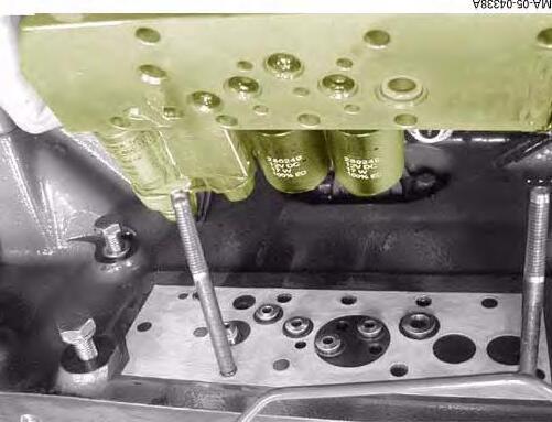
Oil filter1
Fuel filter (microns)prefilter (30) + filter (5)
Sisu engine - General
Model 8460 Engine type
Compression ratio
Compression pressure (kPa) 2000 / 3500
Allowable compression deviation between cylinders (kPa) 350
Output at 2,200 rpm ch (kw) ISO 235 (173)
Maximum torque (Nm) 990 at
(rpm)
Pre- / Post-heating
Injection pump
Trademark and typeBosch VP44
RotationClockwise
Static timing angle (degrees)26°
Engine positionTDC
Engine check angle (degrees)pin
Injection order1-5-3-6-2-4
Lift pumpElectric
Injectors
TrademarkStanadyne CodeM33877
Nozzle holder
Nozzle5 ports
New and servicing setting (bar)278
Miscellaneous
Suction systemIntercooler air/air turbocompressor (no wastegate)
Minimum boost pressure at 2,200 rpm at full load (bar)1.3
Number of valves per cylinder2
Valve springsimple
Valve seat insert (Inlet / Exhaust)yes / yes
Inlet / Exhaust valve angle35° / 45°
Inlet / Exhaust valve tip clearance (mm)0.35 / 0.35
Oil cooleryes
Number of temperature switches2
Opening temperature (start/full)83°C
Fan Vistronic
Piston cooling nozzleyes
Oil filter1
Fuel filter (microns)prefilter (30) + filter (5)
Sisu engine - General
Model 8470
Engine type SISU 84 ETA
Number of cylinders 6
Bore 111
Stroke
Compression ratio 17.5/1
Compression pressure (kPa) 2000 / 3500
Allowable compression deviation between cylinders (kPa) 350
Output at 2,200 rpm ch (kw) ISO 260 (191)
Maximum torque (Nm) 925 at speed (rpm) 1100
Idle speed 800
Nominal speed 2200
Maximum speed at no load 2350
Pre- / Post-heating yes
Wet cylinder sleeves yes
Weight (kg) 660
Injection pump
Trademark and typeBosch VP44 RotationClockwise
Static timing angle (degrees)28°
Engine positionTDC
Engine check angle (degrees)pin
Injection order1-5-3-6-2-4
Lift pumpElectric
Injectors
TrademarkStanadyne CodeM33877
Nozzle holder
Nozzle5 ports
New and servicing setting (bar)278
Miscellaneous
Suction systemIntercooler air/air turbocompressor (no wastegate)
Minimum boost pressure at 2,200 rpm at full load (bar)1.1
Number of valves per cylinder2
Valve springsimple
Valve seat insert (Inlet / Exhaust)yes / yes
Inlet / Exhaust valve angle35° / 45°
Inlet / Exhaust valve tip clearance (mm)0.35 / 0.35
Oil cooleryes
Number of temperature switches2
Opening temperature (start/full)83°C
Fan Vistronic
Piston cooling nozzleyes
Oil filter1
Fuel filter (microns)prefilter (30) + filter (5)
Sisu engine - General
Model
Compression ratio
Compression pressure (kPa) 2000 / 3500
Allowable compression deviation between cylinders (kPa)
Output at 2,200 rpm ch (kw) ISO 290 (213)
Maximum torque (Nm)
(rpm)
Pre- / Post-heating
Injection pump
Trademark and typeBosch VP44
RotationClockwise
Static timing angle (degrees)28°
Engine positionTDC
Engine check angle (degrees)pin
Injection order1-5-3-6-2-4
Lift pumpElectric
Injectors
TrademarkStanadyne CodeM33877
Nozzle holder
Nozzle5 ports
New and servicing setting (bar)278
Miscellaneous
Suction systemIntercooler air/air turbocompressor (no wastegate)
Minimum boost pressure at 2,200 rpm at full load (bar)1.2
Number of valves per cylinder2
Valve springsimple
Valve seat insert (Inlet / Exhaust)yes / yes
Inlet / Exhaust valve angle35° / 45°
Inlet / Exhaust valve tip clearance (mm)0.35 / 0.35
Oil cooleryes
Number of temperature switches2
Opening temperature (start/full)83°C
Fan Vistronic
Piston cooling nozzleyes
Oil filter1
Fuel filter (microns)prefilter (30) + filter (5)
Massey Ferguson
03B10 - SISU TIER 3 ENGINE - General
CONTENTS
A .Introduction.
B .Specifications and standards concerning fuel, oil and coolant
C .Main specifications.
Massey Ferguson
A . Introduction
This section only provides general information about Sisu engines used in this tractor range.
B . Specifications and standards concerning fuel, oil and coolant
The quality of fluids used in these engines, as well as the servicing schedule, must be respected to keep pollution emission levels low and to maintain the tractor's performance throughout its service life.
Fuel quality
The fuel must comply with standard DIN EN 590 andwith the following specifications:
Density (at 15°C): 0.82 to 0.86 kg/dm3
Viscosity (at 40°C): 2 to 4.5 mm²/sec
Cetane Index: min 45
Sulphur content: max 0.20% of weight
Water content: max 200 mg/kg
Oil quality
The oil used must comply with standard API CI-4.
Coolant quality
The coolant used must comply with standard BS6580-1992. It should be a permanent, ethylene/ glycol type coolant.
C . Main specifications
Model 8450
Engine typeSISU 74 CTA
Number of cylinders6
Bore 108
Stroke134
Cubic capacity7.4
Compression ratioN/A
Compression pressure (kPa)N/A
Permissible compression deviation between cylinders (kPa)N/A
Output at 2200 rpm (kw) ISO167
Maximum torque (Nm)970 at speed (rpm)1500
Idle speed800
Nominal speed2200
Maximum speed at no load2250
Pre-/Post-heatingYES
Wet linersYES
Weight (kg)525
Injection pump
Brand and typeBosch CP3.3
RotationClockwise
Static timing angle (degrees)N/A
Engine positionN/A
Engine check angle (degrees)N/A
Firing order1, 5, 3, 6, 2, 4
Fuel lift pumpElectric
Injectors
BrandBosch
New and servicing setting (bar)N/A
Miscellaneous
Aspiration systemIntercooler air/air turbocompressor (no wastegate)
Number of valves per cylinder4
Valve springsimple
Valve seat insert (inlet/exhaust)yes
Valve angleN/A
Inlet/exhaust valve tip clearance (mm)0.35/0.35
Oil cooleryes
Number of temperature switches1
Opening temperature (start/full)79°C/93°C
Piston cooling nozzleyes
Oil filter1
Fuel filterPrefilter (30µ) + filter (5µ)
Number of temperature switches2
Opening temperature (start/full)83°C/93°C
Fan Vistronic
Piston cooling nozzleyes
Lubrication systemGear pump
CLICK HERE TO DOWNLOAD THE COMPLETE MANUAL
• Thank you very much for reading the preview of the manual.
• You can download the complete manual from: www.heydownloads.com by clicking the link below
• Please note: If there is no response to CLICKING the link, please download this PDF first and then click on it.
CLICK HERE TO DOWNLOAD THE
SISU TIER 3 ENGINE - General
Model 8460
Engine typeSISU 74 CTA
Number of cylinders6
Bore 108
Stroke134
Cubic capacity7.4
Compression ratioN/A
Compression pressure (kPa)N/A
Permissible compression deviation between cylinders (kPa)N/A
Output at 2200 rpm (kw) ISO178.5
Maximum torque (Nm)1071 at speed (rpm)1500
Idle speed800
Nominal speed2200
Maximum speed at no load2250
Pre-/Post-heatingYES
Wet linersYES
Weight (kg)525
Injection pump
Brand and typeBosch CP3.3
RotationClockwise
Static timing angle (degrees)N/A
Engine positionN/A
Engine check angle (degrees)N/A
Firing order1, 5, 3, 6, 2, 4
Fuel lift pumpElectric
Injectors
BrandBosch
New and servicing setting (bar)N/A
Miscellaneous
Aspiration systemIntercooler air/air turbocompressor (no wastegate)
Number of valves per cylinder4
Valve springsimple
Valve seat insert (inlet/exhaust)yes
Valve angleN/A
Inlet/exhaust valve tip clearance (mm)0.35/0.35
Oil cooleryes
Number of temperature switches1
Opening temperature (start/full)79°C/93°C
Piston cooling nozzleyes
Oil filter1
Fuel filterPrefilter (30µ) + filter (5µ)
Number of temperature switches2
Opening temperature (start/full)83°C/93°C
Fan Vistronic
Piston cooling nozzleyes
Lubrication systemGear pump
SISU TIER 3 ENGINE - General
Model 8470
Engine typeSISU 84 CTA
Number of cylinders6
Bore 111
Stroke145
Cubic capacity8.4
Compression ratioN/A
Compression pressure (kPa)N/A
Permissible compression deviation between cylinders (kPa)N/A
Output at 2200 rpm (kw) ISO197
Maximum torque (Nm)1195
at speed (rpm)1500
Idle speed800
Nominal speed2200
Maximum speed at no load2250
Pre-/Post-heatingYES
Wet linersYES
Weight (kg)650
Injection pump
Brand and typeBosch CP3.3
RotationClockwise
Static timing angle (degrees)N/A
Engine positionN/A
Engine check angle (degrees)N/A
Firing order1, 5, 3, 6, 2, 4
Fuel lift pumpElectric
Injectors
BrandBosch
New and servicing setting (bar)N/A
Miscellaneous
Aspiration systemIntercooler air/air turbocompressor (no wastegate)
Number of valves per cylinder4
Valve springsimple
Valve seat insert (inlet/exhaust)yes
Valve angleN/A
Inlet/exhaust valve tip clearance (mm)0.35/0.35
Oil cooleryes
Number of temperature switches1
Opening temperature (start/full)83°C/93°C
Piston cooling nozzleyes
SISU TIER 3 ENGINE - General
Model 8480
Engine typeSISU 84 CTA
Number of cylinders6
Bore 111
Stroke145
Cubic capacity8.4
Compression ratioN/A
Compression pressure (kPa)N/A
Permissible compression deviation between cylinders (kPa)N/A
Output at 2200 rpm (kw) ISO216
Maximum torque (Nm)1280 at speed (rpm)1500
Idle speed800
Nominal speed2200
Maximum speed at no load2250
Pre-/Post-heatingYES
Wet linersYES
Weight (kg)650
Injection pump
Brand and typeBosch CP3.3
RotationClockwise
Static timing angle (degrees)N/A
Engine positionN/A
Engine check angle (degrees)N/A
Firing order1, 5, 3, 6, 2, 4
Fuel lift pumpElectric
Injectors
BrandBosch
New and servicing setting (bar)N/A
Miscellaneous
Aspiration systemIntercooler air/air turbocompressor (no wastegate)
Number of valves per cylinder4
Valve springsimple
Valve seat insert (inlet/exhaust)yes
Valve angleN/A
Inlet/exhaust valve tip clearance (mm)0.35/0.35
Oil cooleryes
Number of temperature switches1
Opening temperature (start/full)83°C/93°C
Piston cooling nozzleyes
Massey Ferguson
03B11 - SISU TIER 3 ENGINE - Removing and refitting
CONTENTS
A .Checking the valve timing adjustment.
B .Removing and refitting an injector.
C .Removing and refitting the high pressure pump (Fig.17)
D .Checking and adjusting the valve tip clearance (Fig.18)
E .Description of the EEM.
SISU TIER 3 ENGINE - Removing and refitting
A . Checking the valve timing adjustment
Checking the valve timing adjustment
NOTE: The engine oil must be drained before opening the timing housing. Use a new seal for the cover of the timing housing.
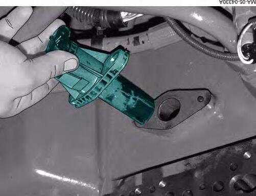
1. Remove the fan, the belt (1), the alternator (2) and the air conditioning compressor if the tractor has air conditioning.
2. Remove the crankshaft pulley (3) and the damper (4).
3. Unscrew the crankshaft nut (5) by two turns, without actually removing it (service tool ref.902455800).
NOTE: The nut will serve as a retainer when removing the hub.
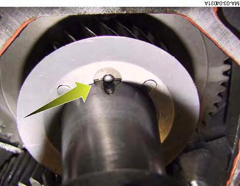
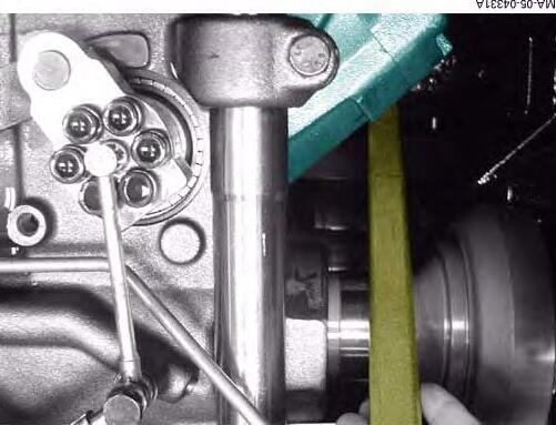
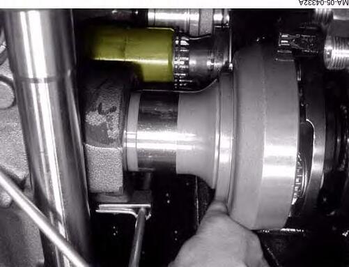
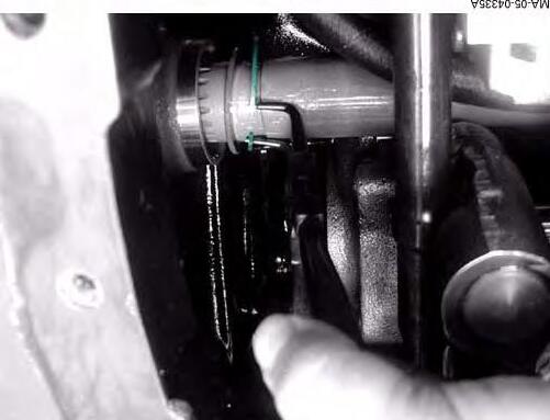
4. Fit the extracting tool (service tool ref. 910453300) onto the crankshaft hub and extract the hub (Fig.2).
5. Take off the extracting tool, remove the crankshaft nut and remove the hub.
6. On 84CTA engines, remove the water pump screws and mark them.
7. Remove the screws from the timing cover and the belt tensioner (19 screws for 74CTA engines, 22screws for 84CTA engines).
NOTE: Mark the long screws and the short screws, and their locations.
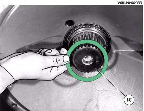
8. Turn the crankshaft pinion in the direction that the engine turns, until the mark of the crankshaft pinion is lined up with that of the intermediary pinion.
IMPORTANT: Do not force if it blocks during rotation.
Fig. 1
SISU TIER 3 ENGINE - Removing and refitting
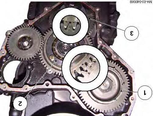
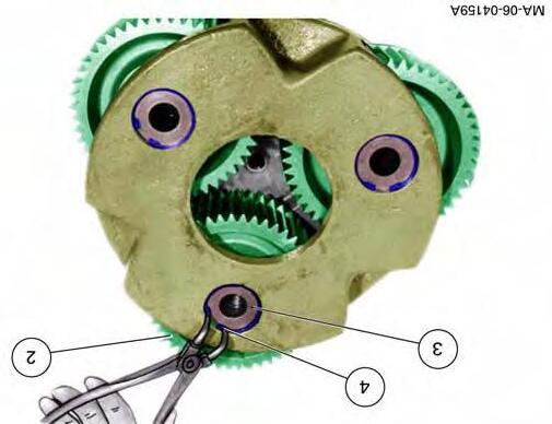
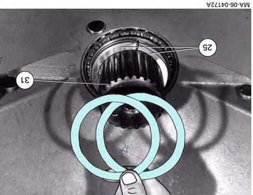
9. The marks of the intermediary pinion must be lined up with those of the camshaft and the crankshaft (Fig.3). If the marks do not line up, proceed as follows:
10. Remove the intermediary pinion (2) (Fig.3).
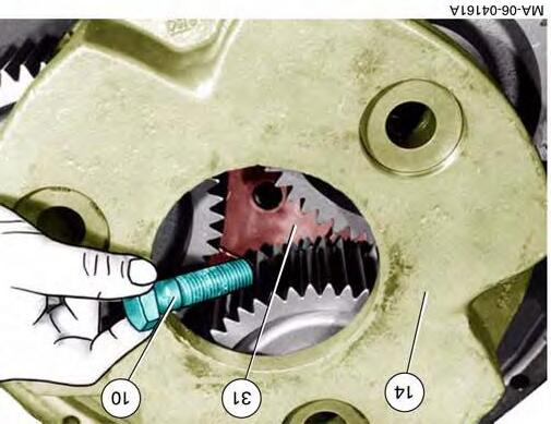
11. Turn the crankshaft (3) (Fig.3) to move the pinion mark vertically; in this position, the cylinder piston n° 1(timing side) should be at top dead centre (TDC).
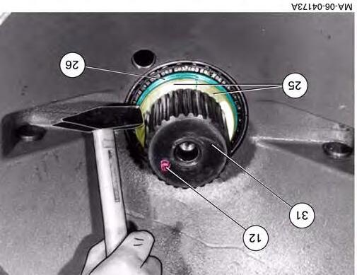
12. Turn the camshaft to bring the valves of cylinder n°6 (engine flywheel side) to the "rock" position, i.e. to the point when the exhaust valves close, and the inlet valves open.
13. Then fit the intermediary pinion so that the marks are lined up (Fig.3).
NOTE: It may be necessary to turn the crankshaft slightly to line up the marks correctly.
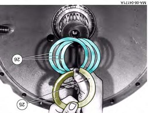
14. Fit the oil pipe washer.
NOTE: Pay close attention to the way it is fitted, see Fig.4
15. Fit the centring tool onto the timing housing.
Engine typeTool ref
74CTA920130270 (Fig.5)
84CTA920130290 (Fig.6)
16. Fit the centring screws of the tool on the intermediary pinion.
17. Tighten the nuts of the intermediary pinion to the corresponding torque:
18. Remove the centring tool.
19. Check the backlash. Value: 0.05 to 0.25 mm
20. Fit a new cover seal.
21. Fit the cover, making sure that the centring pins are located properly.
22. Fit the cover screws but do not tighten them.
M14 : 180 Nm M8 : 45 Nm
Fig. 3
Fig. 4
920130270
Fig. 5
SISU TIER 3 ENGINE - Removing and refitting
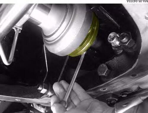
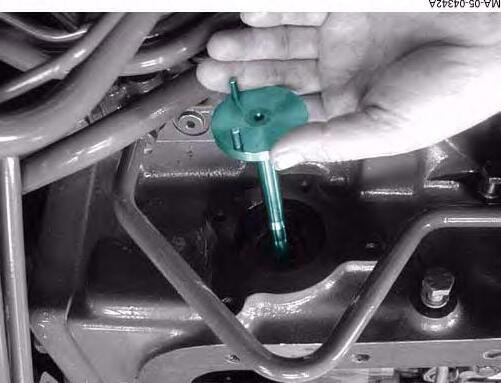
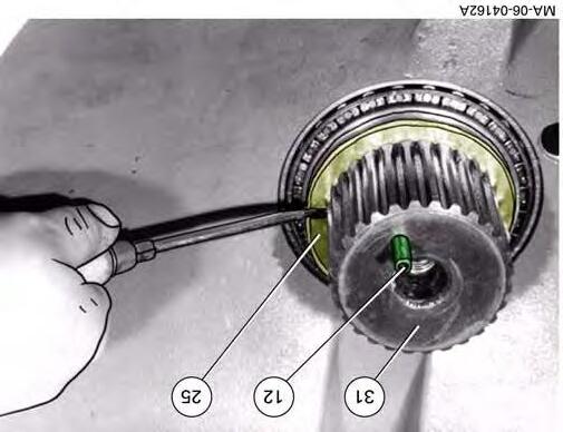
23. Using service tool 910394600, fit a new seal on the crankshaft (Fig.7).
24. Grease the seal, the threads of the crankshaft and the hub.
25. Fit the crankshaft hub.
26. Fit the crankshaft nut and tighten it to the corresponding torque:
27. Tighten the nuts on the timing cover.
28. Refit the components removed as indicated at the start of the paragraph.
29. Add the engine oil and check the level.
910394600
920130290
MA-03-04010A
Fig. 6
MA-03-04012A
Fig. 7
SISU TIER 3 ENGINE - Removing and refitting
B . Removing and refitting an injector
NOTE: This chapter is a general guide to the repair of certain components of the injection system, such as the replacement of an injector, the replacement of the injection common rail or the high-pressure pump. These operations must be carried out by qualified persons equipped with specific tools.
IMPORTANT: The components must be perfectly clean during any servicing operations on the injection system.
All the pipes that are removed must be blocked off.
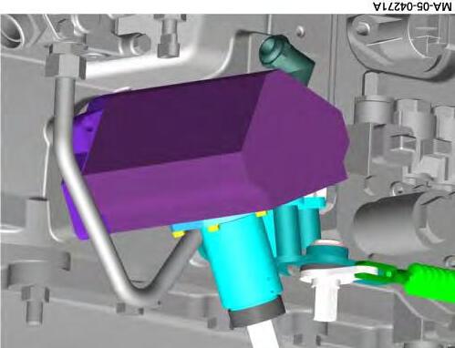
Schematic diagram of the common rail direct injection system
(1)Tank
(2)Electrical suction pump (3)30µ prefilter
(4)Water filter
(5) 5µ main filter
(6)Temperature sensor
(7)Pressure sensor
(8)High-pressure pump
(9)Common rail
(10)Overpressure valve
(11)Injector
(12)Common rail pressure sensor
SISU TIER 3 ENGINE - Removing and refitting
Operation of the fuel circuit
The electric pump (2) draws up the fuel through theprefilter (3) and delivers it to the main filter (5).
Thehigh-pressure pump (8) uses its booster pump to draw the fuel from the main filter and delivers it at high pressure (approx. 1200 bar) into the common rail (9).
The calculator controls each injector (11) independently and thus allows fuel injection in the cylinder at a precise point in the engine cycle. Excess fuel returns to the fuel tank through the return pipes.
CLICK HERE TO DOWNLOAD THE COMPLETE MANUAL
• Thank you very much for reading the preview of the manual.
• You can download the complete manual from: www.heydownloads.com by clicking the link below
• Please note: If there is no response to CLICKING the link, please download this PDF first and then click on it.
CLICK HERE TO DOWNLOAD THE
SISU TIER 3 ENGINE - Removing and refitting
Removing an injector
DANGER: Never open the high-pressure circuit with the engine running. Fuel under pressure can penetrate the skin or eyes and cause serious personal injury, blindness or death. Contact a doctor urgently in the event of an accident. Wait at least 30 seconds after turning the engine off before any servicing.
30. Clean all around the injectors and pipes.
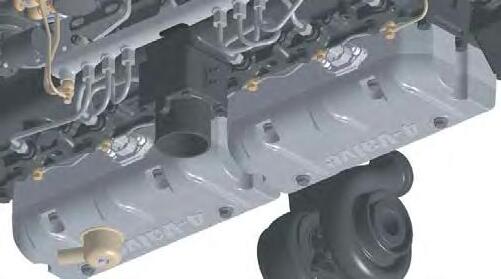
31. Remove the cylinder head cover.
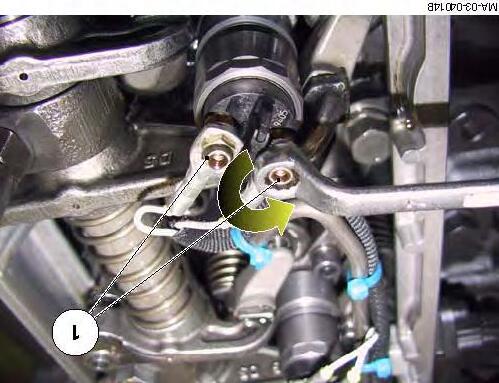
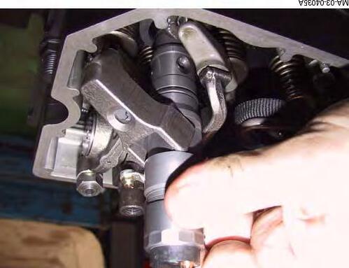
32. Remove the protective cap and take out thecontact nuts (1) (Fig.9), then disconnect the electrical connections.
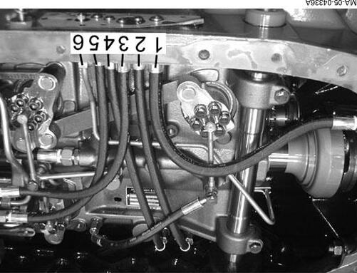
33. Remove the injector supply pipe, and remove the nut (6) (Fig.10) from the high-pressure supply pipe.
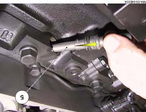
34. Remove the high-pressure supply pipe (5) (Fig.11).
Fig. 9
Fig. 10
Fig. 11
SISU TIER 3 ENGINE - Removing and refitting
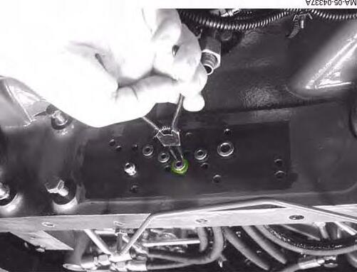
35. Remove the screw (2), the washer (3) and the flange (4).
IMPORTANT: The injectors and the supply pipes are calibrated together. Do not mix up the different pipes and injectors during removal.
36. Take out the injector and the flange. If it is not stuck on the injector, remove the seal ring (7) (Fig.14).
Clean all components.
Refitting an injector
NOTE: A new high-pressure pipe must be fitted between the injector and the common rail to avoid any leaks.
37. Clean the injector seat on the cylinder head. Fit a new seal ring and a new "O" ring.
38. Fit the injector in its housing. Fit the high-pressure supply pipe (5), in the correct direction (see arrow, Fig.14)
39. Tighten the screws following the steps below: -Pre-tighten the screw (2) to a torque of:
Fig.
SISU TIER 3 ENGINE - Removing and refitting
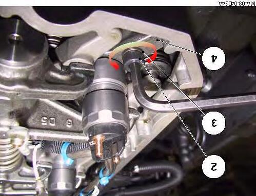
40. Unscrew the screw (2) (Fig.15) and pre-tighten the nut (6) to a torque of:
41. Tighten the screw (2) (Fig.15) to a torque of:
42. Tighten the nut (6) (Fig.15) to a torque of:
43. Fit a new high-pressure pipe (8) (Fig.15) between the injector and the common rail, and tighten the union to a torque of:
44. Refit the electrical power supplies (9) (Fig.15), and tighten M4 nuts to a torque of:
45. Refit the protective cap onto the injector.
46. Refit the cylinder head cover (11) (Fig.16), using a new seal.
47. Tighten the screws (10) (Fig.16) of the cylinder head cover to a torque of:
48. Check again that there are no leaks in the high-pressure circuit.
MA-03-04015A
MA-03-04016A
Fig. 16
SISU TIER 3 ENGINE - Removing and
refitting
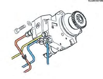
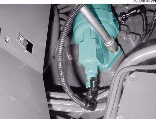
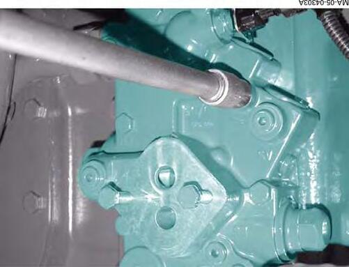
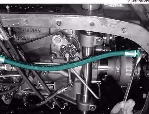
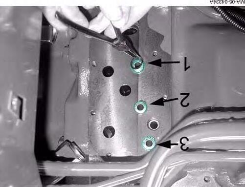
C . Removing and refitting the high pressure pump (Fig.17)
DANGER: Never open the high-pressure circuit with the engine running. Fuel under pressure can penetrate the skin or eyes and cause serious personal injury, blindness or death. Contact a doctor urgently in the event of an accident. Wait at least 30 seconds after turning the engine off before any servicing.
Removal
49. Clean all around the pump and the high-pressure unions.
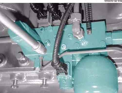
50. Disconnect the electrical connector (1).
51. Remove the fuel pipes, and block their ends (2).
52. Remove the 3 screws from the pump (3).
53. Remove the high-pressure pump (4).
54. Use an extracting tool to remove the pinion (5).
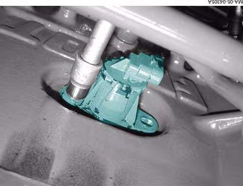
Refitting
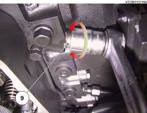
55. Fit a new "O" ring (6).
56. If the timing cover has not been removed, fit the pinion (5) onto the new pump. If the timing cover has been removed, the pinion may be fitted by the timing housing.
57. Fit and tighten the pinion fastening nut (5) of the pump to the corresponding torque:
58. Grease the "O" ring (6), and fit the high-pressure pump (4) in its location.
Fig. 17
SISU TIER 3 ENGINE - Removing and refitting
59. Fit and tighten the screws (3) to a torque of:
NOTE: There is no setting mark on the pinion of the high-pressure pump; the position of the pinion is free in relation to the other timing pinions.
60. Fit the fuel pipes and tighten the unions to the corresponding torques: -Low pressure
-High pressure
61. Refit the electrical connector (1).
SISU TIER 3 ENGINE - Removing and refitting
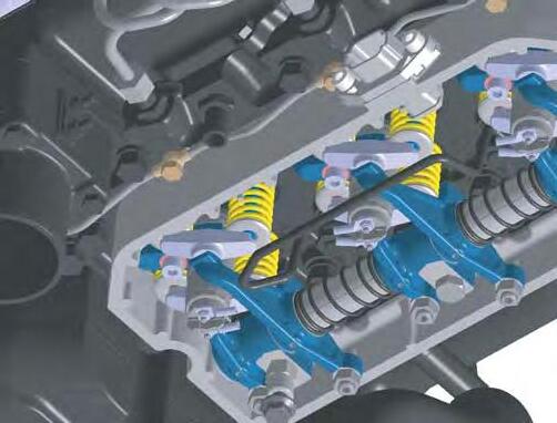
D . Checking and adjusting the valve tip clearance (Fig.18)
NOTE: It is advisable to change the seal of the cylinder head cover during this operation.
62. Remove the screws (10).
63. Remove the cylinder head cover (11).
64. Turn the crankshaft to bring the valves of cylinder n° 6 to the rock position (Fig.19).
65. On cylinder n° 1 (Fig.19), unscrew the locknut of the inlet valve adjusting screw.
66. Using a thickness shim, check the clearance between the valve tip and the rod of the inlet valve (1) (Fig.20) using the screw to adjust if necessary.
67. Tighten the locknut then check the clearance again. Repeat the previous operation if necessary, until the correct value is attained.
68. Then carry out the same procedure for the exhaust valve of cylinder n° 1(2) (Fig.20)
69. Turn the crankshaft about 1/3 of a turn in the direction of the engine, then bring the valves of cylinder n° 2 to the rock position. Then carry out the same operations on cylinder n° 5.
70. Carry out the same procedure for the other cylinders, referring to the table below to start the adjustment:
Firing order153624
Valves on the rock on cyl. n°624153
71. Refit the cylinder head cover using a new seal.
72. Tighten the screws (10) (Fig.18) to a torque of:
MA-03-04016A
Fig. 18
Fig. 19
Fig. 20
SISU TIER 3 ENGINE - Removing and refitting
E . Description of the EEM
General
1Temperature and air pressure sensor8Calculator
2Injectors9Identification module
3Heater
4Fuel pressure sensor
5Electric fuel pump
6Fuel temperature sensor
7Engine flywheel sensor
10Oil pressure sensor
11High-pressure pump
12Injection common rail and high-pressure sensor
13Camshaft sensor
14Water temperature sensor
Fig. 21
SISU TIER 3 ENGINE - Removing and refitting
Details on the different components
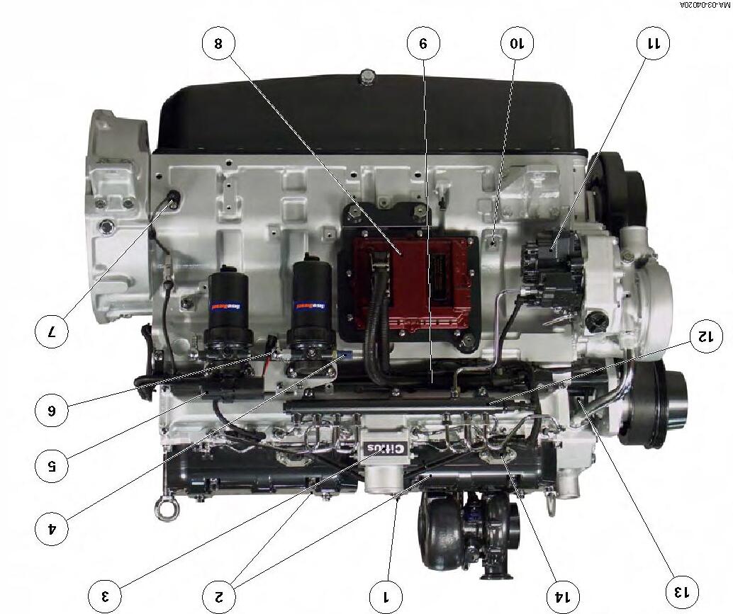
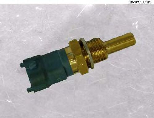
Temperature and air pressure sensor
This sensor constantly measures the temperature and the air pressure in the inlet manifold. It is supplied with 5 V direct current. It is located on the air inlet manifold.
Temperature
The resistance of the sensor decreases as temperature rises.
Nominal resistance:
-at 20°C = 2.5 kΩ -at 100°C = 0.186 kΩ
Pressure
Output voltage:
-at 100 kPa (around air pressure) = 1.07 V -at 200 kPa = 2.21 V
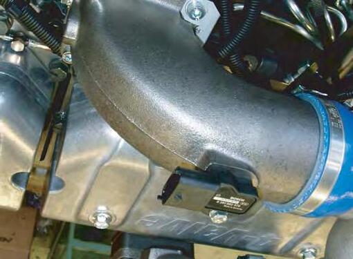
Injector
Current required for opening 25A
Current required to keep open 12A
Delivery pressure from 0 to 10 bar
8-hole injector
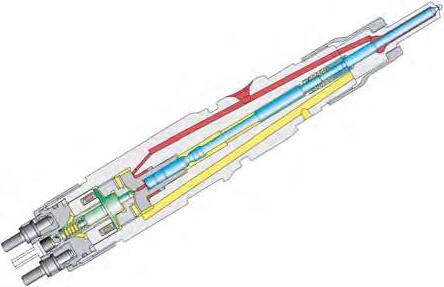
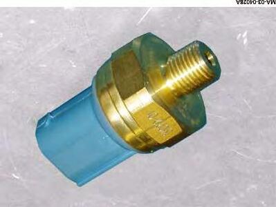
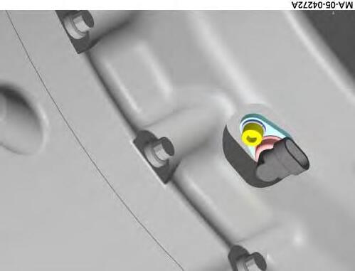
Fuel pressure sensor
This sensor constantly measures the absolute pressure in the supply line of fuel coming from the tank. It is supplied with 5 V direct current. It is located on the main fuel filter.
Output voltage:
-at 0 kPa = 0.5 V -at 360 kPa = 4.9 V (absolute pressure)
MA-03-04021A
Fig. 22
MA-03-04022A
Fig. 23
Fig. 24
SISU TIER 3 ENGINE - Removing and refitting
Fuel temperature sensor
This sensor measures the temperature of the fuel in the supply line coming from the tank. It is supplied with 5 V direct current. It is located on the main fuel filter. The resistance of the sensor decreases as temperature rises.
Nominal resistance values:
-at 20°C = 2.5 kΩ
-at 100°C = 0.186 kΩ
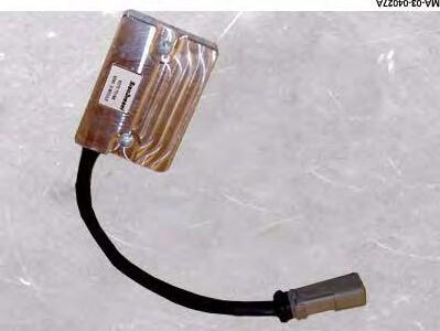
Engine flywheel sensor
This sensor is inductive. It detects each tooth on the engine flywheel (one tooth every 3°) and transmits alternating current to the calculator. If this sensor fails, the camshaft sensor allows the engine to continue to run. Power will, however, be reduced.
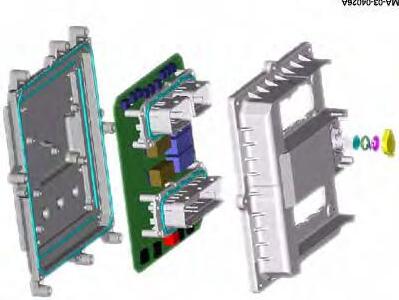
Calculator
12 V supply, but will accept 24 V. This calculator is fitted with an internal digital sensor for atmospheric air pressure.
Fig. 25
Fig. 26
Fig. 27
SISU TIER 3 ENGINE - Removing
and refitting
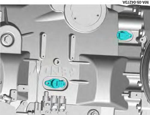
Identification module
This module is fitted onto the left-hand side of the engine block and cannot be removed. It ensures optimal operation during the replacement of the EEM.
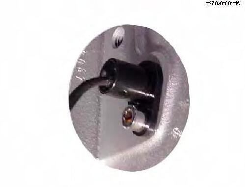
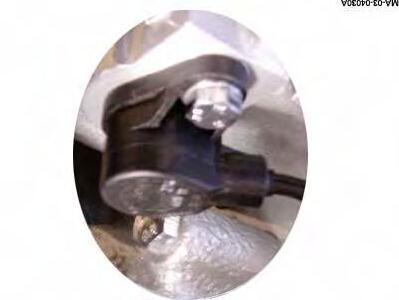
Oil pressure sensor
This sensor constantly measures the absolute pressure of the engine oil. It is supplied with 5 V direct current.
Output voltage:
-at 0 kPa = 0.5 V
-at 360 kPa = 4.5 V It is located on the left-hand side of the engine block.
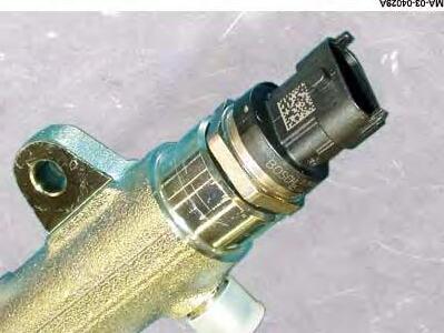
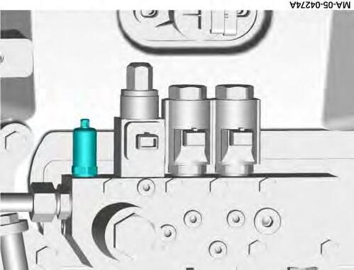
High-pressure sensor on the injection common rail
This sensor measures the pressure in the common rail in relation to the atmospheric air pressure. It is supplied with 5 V direct current. It is located at the end of the injection common rail, towards the front-end of the engine.
Output voltage:
-at 0 MPa = 0.5 V -at 31,800 kMPa = 4.5 V
Fig. 28
Fig. 29
Fig. 30
SISU TIER 3 ENGINE - Removing and refitting
Camshaft sensor
This sensor transmits a signal at each rotation of the camshaft, indicating the point of injection. The camshaft pulley has 7 teeth, 1 for each cylinder + 1 for the top dead centre (TDC) of cylinder n° 1. It is located on the timing housing, just above the camshaft pinion. If this sensor fails, the engine will continue to run, but at reduced power.
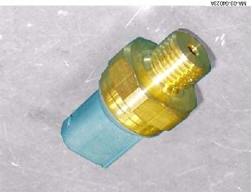
Water temperature sensor
This sensor measures the temperature of the coolant. It is supplied with 5 V direct current. It is situated on the top of the cylinder head. The resistance of the sensor decreases as temperature rises.
Nominal resistance values:
-at 20°C = 2.5 kΩ
-at 100°C = 0.186 kΩ
Fig. 31
Fig. 32
05- Gearbox
CONTENTS
05A01-General - Dyna VT Operation
05B01-DYNAVT hydraulics
05C01-Replacing the DYNAVT unit
Massey Ferguson
CLICK HERE TO DOWNLOAD THE COMPLETE MANUAL
• Thank you very much for reading the preview of the manual.
• You can download the complete manual from: www.heydownloads.com by clicking the link below
• Please note: If there is no response to CLICKING the link, please download this PDF first and then click on it.
CLICK HERE TO DOWNLOAD THE
Gearbox
Massey Ferguson
05A01
- General - Dyna VT Operation
CONTENTS
A .General.
B .DynaVT transmission operating diagrams
C .Operation and use
Massey Ferguson
General - Dyna VT Operation
A . General
Operating principle of the DYNAVT transmission
The DynaVT transmission is a continuously variable transmission in both forward and reverse positions. Hare/Tortoise range switching with synchronisation is incorporated into the transmission. The Tortoise range allows ground speeds of 0 to 32 kph. The Hare range allows ground speeds of 0 to 50 kph (according to country), and the maximum standard speed is electronically limited to 40 kph. The Tortoise range is intended for heavy traction work at low speeds of less than 12 kph. The Hare range is intended for road driving (transport). At 50 kph, the transmission ratio is controlled electronically according to engine speed. Power transmission can be hydrostatic OR mechanical or hydrostatic AND mechanical. In simple terms, we can state:
-Slow forward position = Power transmission: majority = hydrostatic / minority = mechanical -Fast forward position = Power transmission: minority = hydrostatic / majority = mechanical. For detailed explanations, see the transmission operating diagram.
Power transmission hydrostatic circuit
The DynaVT transmission unit is flexible suspended in the transmission housing. This latter also serves as an oil tank for the hydrostatic transmission.
Filling: OilTerrac Extra or Terrac Tractran 9/Fluid 9, or any other oil complying with standard CMS M1143 or CMS M1144.
The lube oil pump sucks oil through the suction strainer. The temperature sensor monitors the transmission oil temperature. In brief, if the transmission oil is cold, little oil passes through the cooler and most goes through the by-pass valve. This valve opens at a differential pressure of approximately 3.5 bars. The hydraulic oil temperature is monitored by the temperature sensor. The service pump supplies the system pressure to the DynaVT control spool valves and comfort control solenoid valves. The system pressure of approximately 18 bars is limited by a pressure-limiting valve with throttling port.
Two different pressures are present in the system.
•Low pressure for the DynaVT transmission control and auxiliary pressure for rear PTO clutch, differential block and universal joint brake. The measuring point of this pressure is approximately 18 bars.
•High pressure in the Dyna VT transmission. Pressure measuring point, approximately 500 + 20 bars.
The oil filter clogging is monitored by a pressure switch according to the transmission oil temperature. When this temperature is lower than 50°C, oil filter clogging is not monitored.
Cooled transmission oil inlet into the high pressure circuit is performed in alternation by two non-return valves. Hot transmission oil outlet from the high pressure circuit occurs through the pressure relief valve.
The high pressure circuit comprises: a variable displacement pump and a hydrostatic motor, two non-return valves, two high pressure limiting valves, one pressure relief valve, one coupler function solenoid valve, one clutch function controlled valve and one check connector. The pump and motor screw cylinders are controlled by two 4/3 spool valves. These 4/3 spool valves are mechanically controlled by the cam channel drive shaft. Rotation of the drive shaft is initiated, according to the need, by the control unit which thus defines the hydraulic capacity and hence the hydraulic power.
The variable displacement pump and hydrostatic motor pivot proportionally. In backup position, the screw shaft is manually activated from the driver’s cab. In limp home position, the transmission automatically blocks at approximately 30 kph after engine start-up. If the clutch pedal, parking brake or neutral switch are used, the high pressure circuit is automatically unloaded by means of two high pressure limiters. The coupler function is controlled by the pressure limiter.
General - Dyna VT Operation
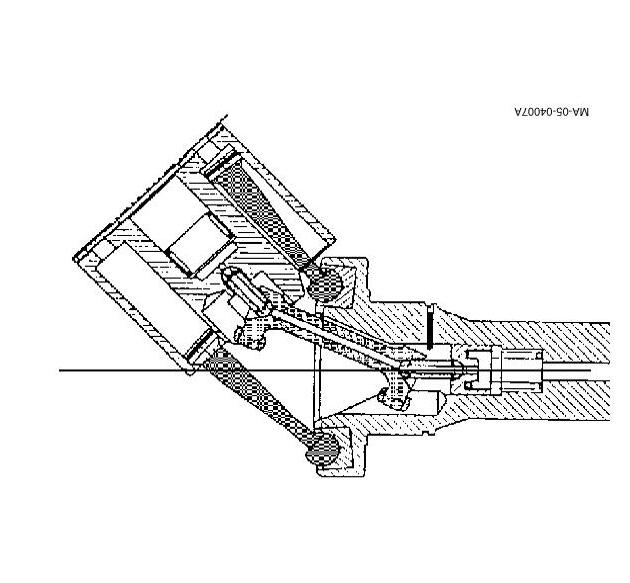
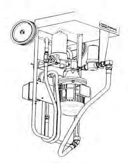
The control unit (Fig.1)
The control unit drives the cam channel drive shaft, which changes the DynaVT transmission ratio. The control unit comprises the following elements:
•Limp home operation control (required in the event of electronic control failure).
•Coupling of the incremental rotational angle sensor with a digital resolution of 8,000 pulses per revolution.
•12 VDC electric motor, 0.4 to 7 amps, vacuum control unit 4,500 rpm
•Friction clutch 2.5 to 3.5 Nm, using the limp home operation socket wrench, 4 to 5 Nm.
Following ignition, the control unit searches for the reference point (approximate neutral point between forward and reverse operation).
Sensors
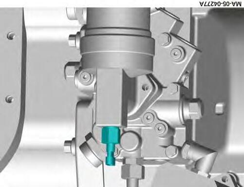
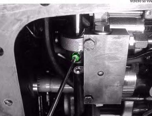
Engine sensor (TR23) (Fig.2): measures engine speed. This sensor measures engine speed. If it fails, only the limp home operation can be used.
Summing shaft (TR19) and drive pinion (TR11) Hall sensor: measures engine speed or rate and recognises the rotational direction (Fig.3).
Fig. 1
Fig. 2
Fig. 3
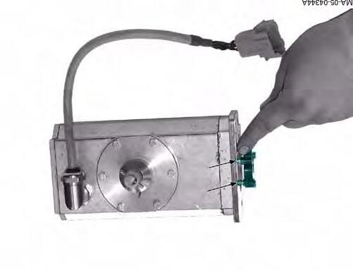
High pressure sensor (TR17) transmits the instantaneous oil pressure in the high pressure oil circuit to the electronic system (Fig.4).
General - Dyna VT Operation
Throttle pedal sensor (CAB 44) (Fig.5): transmits the position of the throttle pedal to the electronic system and compares it to the engine speed. This position sensor is used for load control.
Hare / Tortoise range position sensor (TR8) (Fig.7): electronically monitors the range selector switch position.
Temperature sensor (TR12) (Fig.8): monitors transmission oil temperature. Temperatures greater than 110°C are stored with an error code.
HP filter clogging sensor (TR13) (Fig.9): monitors the clogging of the high pressure filter.
Fig. 7
Fig. 8
Fig. 9
B . DynaVT transmission operating diagrams
Planet carrier Driven by the engine
Epicyclic gear train/Power distribution
: Transmission of mechanical force B : Transmission of hydrostatic force C : Power take-off drive
: Front axle drive
: Range shifting B: Ring gear Drives the hydrostatic pump D: Sun gear pinion Drives the summing shaft C: Pinion gear
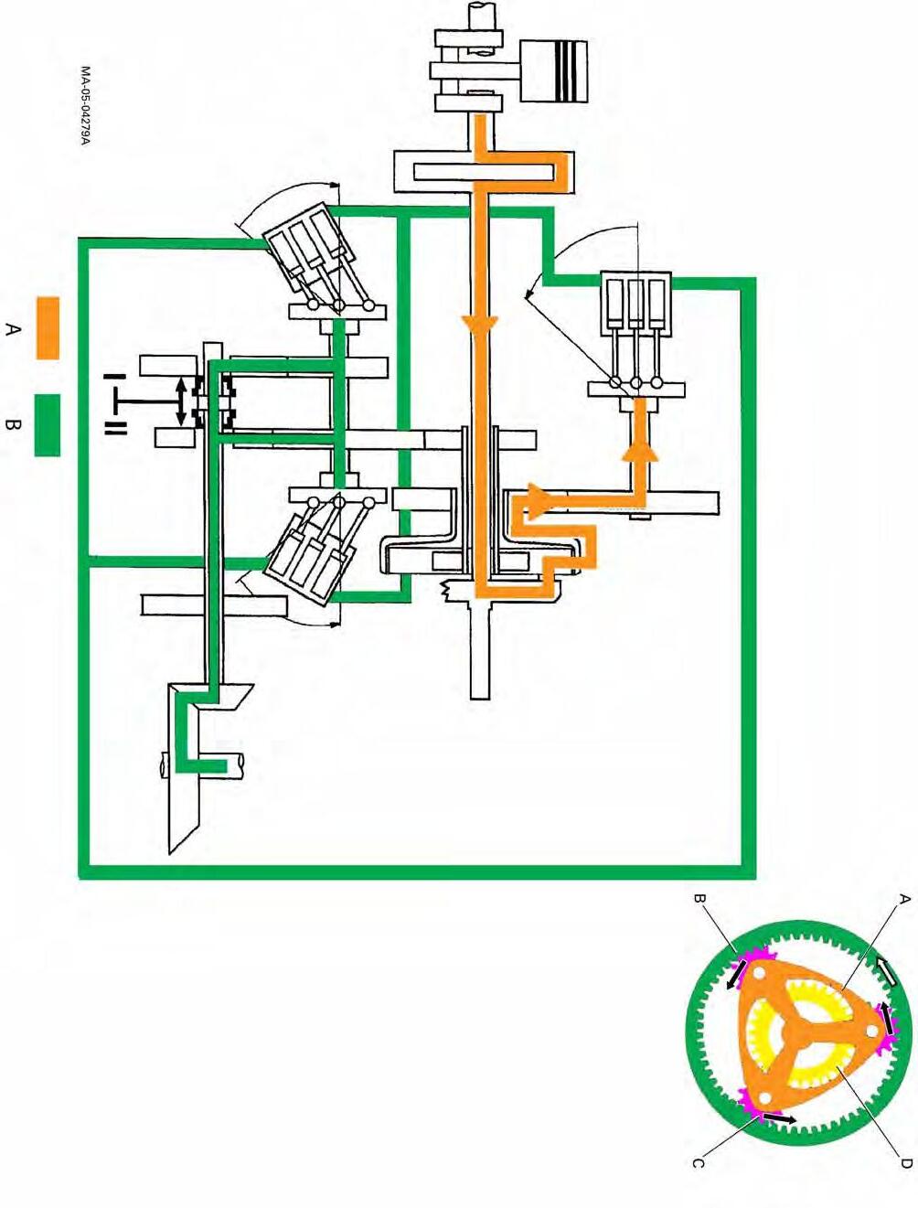
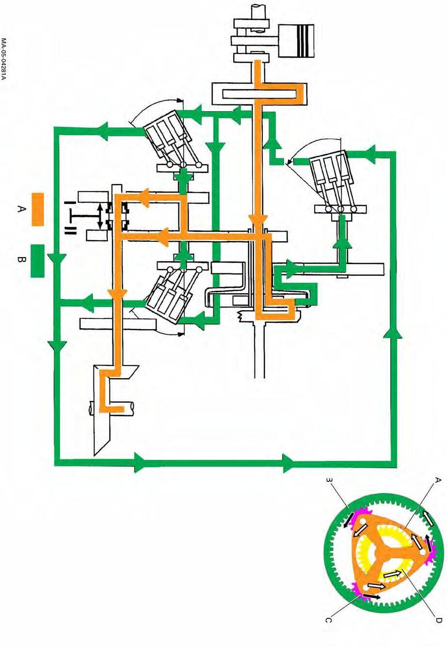
Dynamic stop
ENGINE STARTED, TRACTOR AT STANDSTILL
A : Transmission of mechanical force
B : Transmission of hydrostatic force
•The engine drives the planet carrier (A)
•The ring gear (B) turns, driving the pump (2) without any flow
•The hydrostatic motors 4 do not turn •The sun gear (D) does not turn as it is blocked by the tractor wheels via the rear axle bevel gear
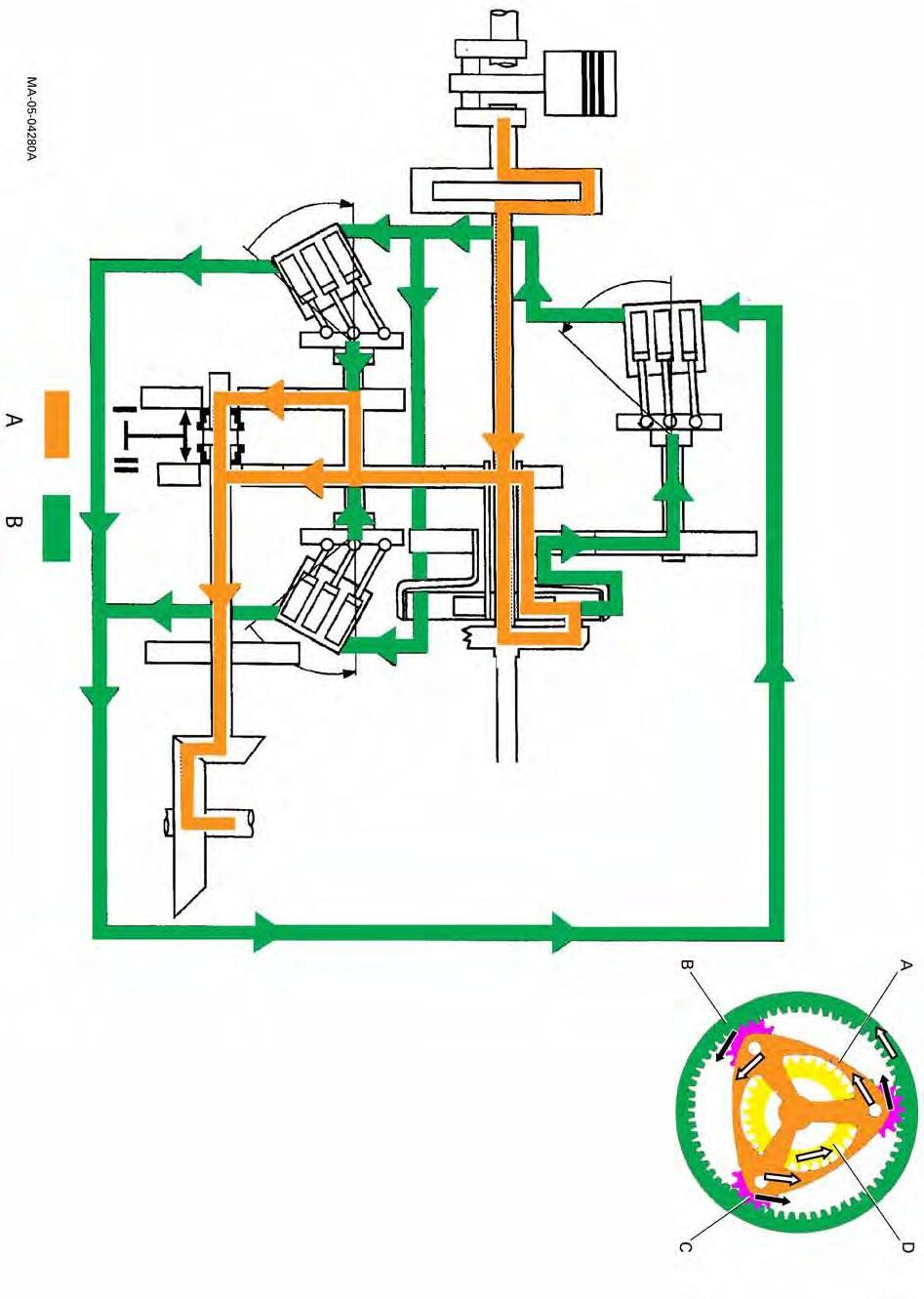
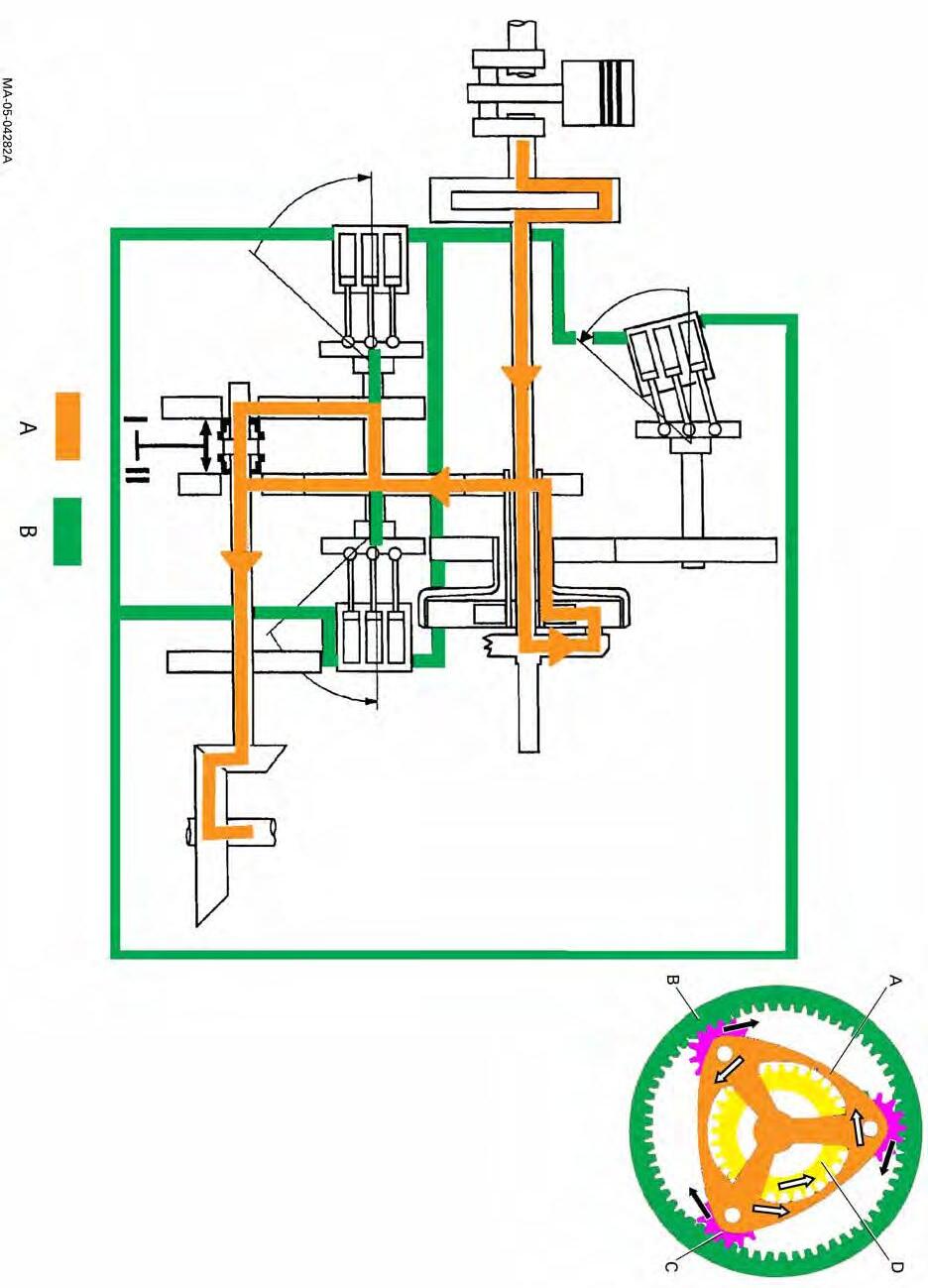
Start-up
A : Transmission of mechanical force
B : Transmission of hydrostatic force
•The pump (2) tilts and supplies flow to the motors (4)
•The motors (4) drive the rear axle
•The sun gear starts to turn and the ring gear speed decreases
Fig. 12
CLICK HERE TO DOWNLOAD THE COMPLETE MANUAL
• Thank you very much for reading the preview of the manual.
• You can download the complete manual from: www.heydownloads.com by clicking the link below
• Please note: If there is no response to CLICKING the link, please download this PDF first and then click on it.
CLICK HERE TO DOWNLOAD THE
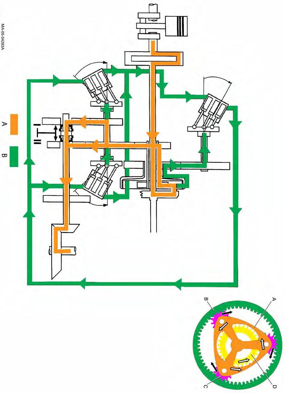
Average ground speed
A : Transmission of mechanical force
B : Transmission of hydrostatic force
•The pump (2) angle increases
•The pump flow increases and the angle of the motors (4) decreases
•The sun gear speed increases, increasing the bevel gear speed
•The planet carrier speed is constant
•The ring gear speed decreases
13
Fig.
A : Transmission of mechanical force
B : Transmission of hydrostatic force
•The angle of the motors (4) is 0° and the flow from the pump is blocked
•The pump (2) is thus blocked stationary, as is the ring gear
•The planet carrier turns
•The sun gear turns, driving the bevel gear on its own
Fig. 14
A : Transmission of mechanical force
B : Transmission of hydrostatic force
•The pump (2) is tilted at the opposite angle, so the flow is reversed
•The motors (4) turn in the opposite direction
•The sun gear thus turns in the opposite direction to the planet carrier and so also drives the bevel gear in the opposite direction
•The ring gear speed increases
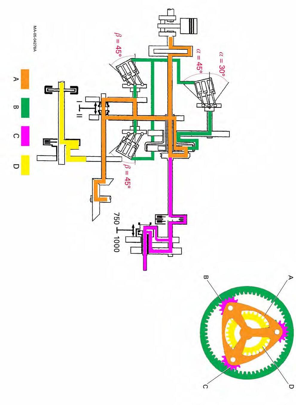
General
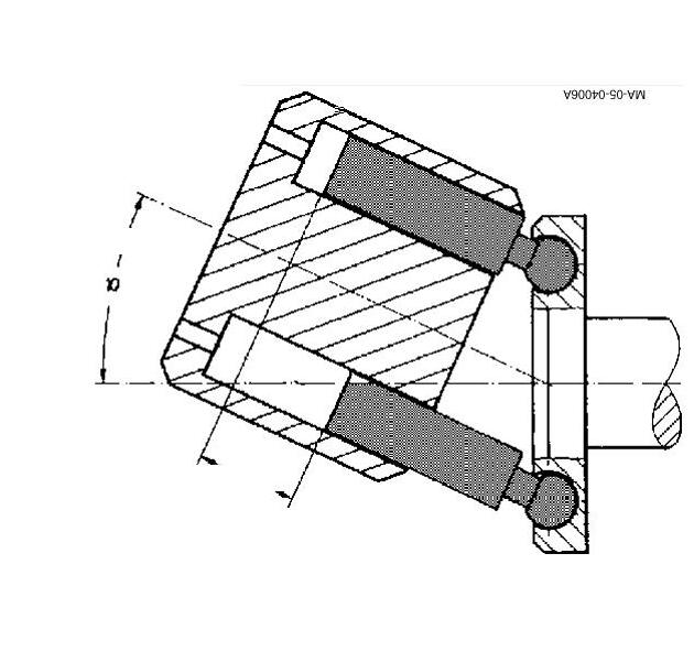
Architecture of the hydrostatic components
For conventional hydrostatic components, the rotational angle only reaches 30°.
Example of a conventional variable displacement pump with axial pistons.
This system, on the other hand, proposes hydrostatic components specially designed to provide a 45° rotational angle.
Example of a special variable displacement pump with axial pistons. This means:
•Higher intrinsic yield of hydrostatic components with respect to conventional components.
•A 45° rotational angle offers the possibility of increasing the ground speed scope, resulting in a decrease in the number of required mechanical ranges.
Piston travel
Angular travel
Fig. 16
Cylinder block
Fig. 17
General - Dyna VT Operation
C . Operation and use
Start-up
Switch on the ignition. The TC 2.10 and DC 2.10 (2.00 being the software version installed in the tractor) symbols flash on the instrument panel right-hand screen (Fig.18).
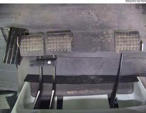
Fully press down the clutch pedal (Fig.19).
The left-hand lever (reverse shuttle) should be in the neutral position (Fig.20). Start the engine and release the clutch pedal.
Fig. 18
Fig. 19
Fig. 20
General - Dyna VT Operation
Selecting movement and direction
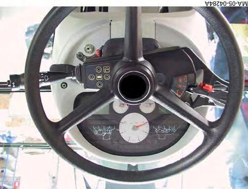
The DynaVT transmission possesses a user interface and a specific display screen. The power shuttle lever (Fig.21) controls direction of travel, and speed increase and decrease.
Set the left-hand lever to the desired direction of movement, the corresponding symbol comes on the relevant screen. When the tractor is in movement, each change of direction is achieved with the left-hand lever (Fig.21).
(1) Neutral position
(2) Forward position
(3) Reverse position
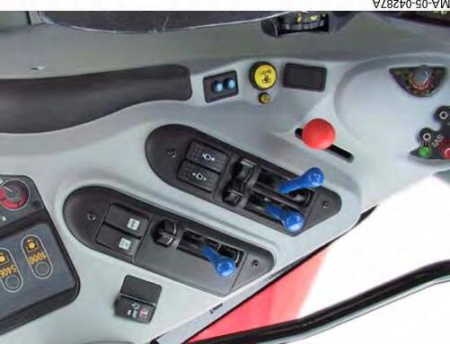
To set the tractor in motion (forward or reverse), adapt the transmission ratio with the right-hand lever, or the plus and minus buttons of the reverse shuttle lever, depending on the desired speed. During tractor movement, if the clutch pedal is activated, the transmission ratio is decreased until speed is zero.
The armrest lever (Fig.22), with no neutral or ParkLock, also controls speed increase and decrease depending on the direction of movement.
Fig.
Fig. 22
General - Dyna VT Operation
Lever mode and pedal mode
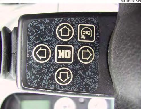
At start-up, the tractor is always in lever mode, transmission control is performed with the lever only (Fig.24).
To activate the various modes (lever, pedal...), use button (1) (Fig.24) with the throttle pedal released. The status of the selected mode is visible on the DOT MATRIX screen (Fig.23 and Fig.26)
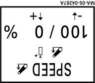
1- In pedal mode, the transmission is exclusively controlled by the pedal. To preset the maximum speed, press the clutch pedal to neutral position, then activate the armrest lever (Fig.22) or the left-hand lever in forward position (Fig.21) to increase or decrease the value displayed on the DOT MATRIX screen (Fig.26). Engine speed is electronically adjusted to the transmission speed. Two variants may be selected when in pedal mode:
1-1. POWER MODE. This is the max. speed at the max. engine speed (no programmed max. engine speed).
1-2. ECO MODE. This is the max. speed at the engine speed of 1,800 rpm (in this mode, 1,800 rpm is the max. engine speed).
2- In lever mode, the speed depends on the movement on the lever on armrest (Fig.22).
3- A third mode may be available, the self-propelled mode. In this mode, the user sets the engine speed with the A and B memories and forward motion is controlled by the throttle pedal and the hand throttle lever (2) (Fig.25) or the armrest speed lever (Fig.22).
Fig. 23
Lever mode
Fig. 24
Fig. 25 2
Fig. 26
Pedal mode
Max. speed
General - Dyna VT Operation
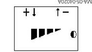
Increasing and decreasing speed
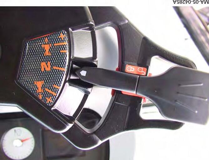
To increase or decrease speed, both levers can be used. The left-hand lever (Fig.27) adjusts speed by increments of 0.1 to 2kph, depending on the duration of lever pressure.
The right-hand lever (Fig.28) makes adjusting the transmission ratio easier thanks to its progressive action.When the ratio decreases, the tractor stops at 0 kph (dynamic stop).
Adjusting the speed throttle lever
The travel of the right-hand armrest lever possesses increments that vary with the position of this latter. There are 3 types of increment(Fig.29):
• 0.03 to 0.5 during the slot 1 or slot 4
•1 during slot 2 or slot 5
•2 during slot 3 or slot 6
NOTE: If speed regulation is active, pressing the lever automatically deactivates it.
Fig. 27
Fig. 28
Fig. 29
General - Dyna VT Operation
Hare / Tortoise range
The DynaVT transmission possesses 2 gear ranges. Each range is limited:
A button (B) on the right-hand console (Fig.32) is used for shifting Hare/Tortoise range. When the tractor is in movement, shifting can only be performed from Tortoise to Hare. For shifting from Hare to Tortoise, the left-hand lever (Fig.27) must be in the neutral position or the clutch pedal depressed.
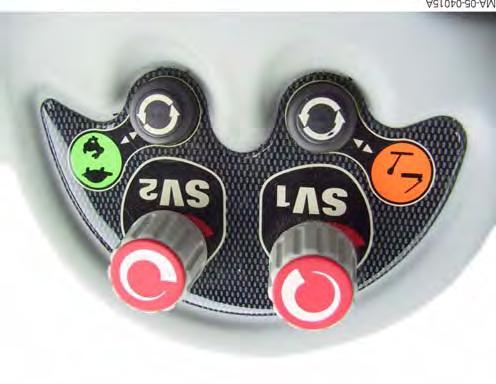
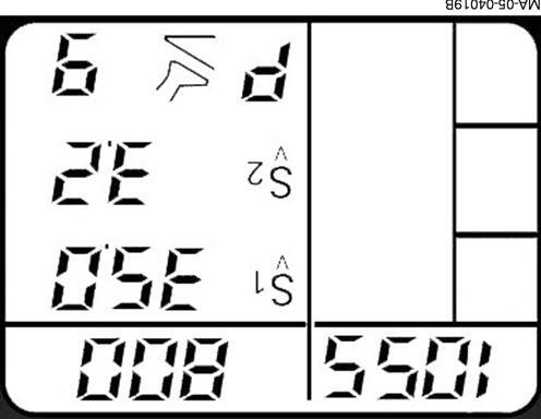
Speed regulator SV1 and SV2
The ground speed is kept constant.
The “speed regulator” function enables the user to store a ground speed and to recall it easily.
Two independent memory keys (SV1 and SV2) are available (Fig.33). This allows two speeds to be memorised (e.g.: working speed and transport speed).
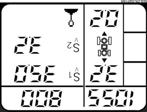
The memorised speeds are displayed to the right of the Dot Matrix screen (Fig.34) (A) and (B). When the “speed regulator” is used, the screen display is as in Fig.34
“SV1” activation indicator (D)
“SV2” activation indicator (E)
Fig. 32
Fig. 33
Memorising SV1 and SV2
Fig.
Preset speeds using the SV1 and SV2 potentiometers (Fig.35)
After having called up the “speed regulator” menu, the ground speed can be adjusted using the SV1 and SV2 potentiometers. The adjusted values are automatically stored and remain in memory even after the tractor is turned off.
NOTE: It is also possible to change the stored speed when the tractor is driving with an activated "regulated" speed.
It is possible to switch from one memory to the other simply by pressing the SV1 and SV2 buttons (Fig.33). If buttons SV1 or SV2 (Fig.33) are pressed down for more than 3 seconds, the current speed is memorised and replaces the previous stored value.
The "speed regulator" can only be activated if the following conditions have been met:
•Clutch pedal not activated
•The tractor is in movement
•Engine speed greater than 1,100 rpm
If these conditions are not met the "speed regulator" function is deactivated and the instantaneous transmission ratio is maintained, with no subsequent control. Start-up with the “speed regulator” function is not possible. Stored speeds can be activated in both directions of movement.
“Speed regulator” control ceases when:
•The drive lever is used
•The foot brake or the engine brake is used
•Engine speed drops below 1,100 rpm
•The neutral switch is activated
•The driver switches from Tortoise to Hare.
General - Dyna VT Operation
tors
Fig. 35
Adjusting speed regula-
Fig. 36
Supervisor icon
CLICK HERE TO DOWNLOAD THE COMPLETE MANUAL
• Thank you very much for reading the preview of the manual.
• You can download the complete manual from: www.heydownloads.com by clicking the link below
• Please note: If there is no response to CLICKING the link, please download this PDF first and then click on it.
CLICK HERE TO DOWNLOAD THE
General - Dyna VT Operation
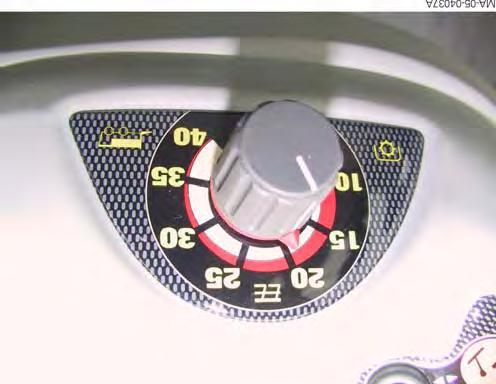
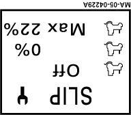
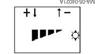
Engine underspeed supervisor
This supervisor is used to limit the drop in engine speed and to adapt it to engine output. When operating at the engine maximum output, the driver must constantly adapt the tractor speed with the controls in order to remain within the appropriate power range. Permanent comparison is performed between the specified output speed (position of the throttle pedal) and the engine speed.
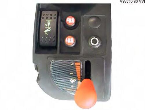
The underspeed supervisor is automatically triggered when the engine speed drops under the effect of a load. The supervisor value is set by means of the potentiometer located on the right-hand console (Fig.37). When the engine underspeed supervisor is active, an icon is displayed on the left-hand screen (Fig.36). Control is activated only if the engine speed drops by more than 180 rpm.
Potentiometer set to 10:
The ground speed decreases to maintain a constant engine speed.
Potentiometer set to 40:
The engine speed increases to maintain a constant ground speed.
Potentiometer set between 10 and 40: Combination of the two previous explanations.
Adjusting the underspeed supervisor
Fig. 37
General - Dyna VT Operation
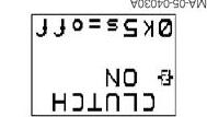
Clutch-coupler function (CLUTCH)
Clutch function
Although the DynaVT transmission has neither forward clutch nor coupler, the tractor possesses a clutch pedal.
The clutch pedal is used for dosing the traction effort (in a similar manner to conventional clutch slipping). When an obstacle appears suddenly, the tractor can be rapidly stopped, just like a conventional tractor, by pressing the clutch and brake pedals.
Coupler function
Traction power is limited at low engine speed thanks to a pressure relief valve located on the transmission hydrostatic loop.
In connection with engine speed, the coupler function is achieved by modulating the pressure in the hydrostatic circuit. Thus, the coupler function replaces the measured action of a clutch pedal.
Coupler function under traction
The coupler function enters into action as soon as engine speed drops below 1,400 rpm. Pressure drops in the hydrostatic loop in proportion to the drop in engine speed.
Just like a coupler, the function limits engine overload and avoids stalling.
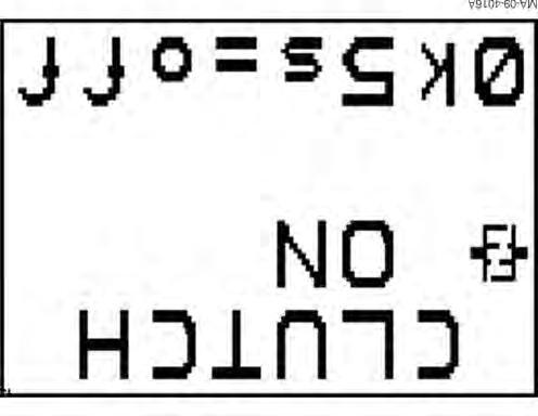
The coupler function can be validated with the DOT MATRIX (Fig.38).
NOTE: to activate (Fig.38) or deactivate (Fig.39) the coupler function, press the OK key for 5 seconds.
The coupler function is "ON" by default at start-up whatever the status when the tractor engine is stopped.
Fig. 38
Fig. 39
General - Dyna VT Operation
Fast reversing
When changing the direction of movement, the tractor decreases to a halt, then accelerates in the opposite direction. Reversing is not possible if the following functions are active:
•underspeed supervisor
•speed regulator
•turbo clutch function
If the clutch pedal is pressed during fast reversing, a temporary stop may occur.
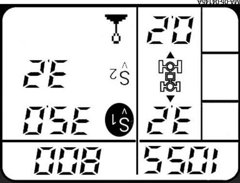
Setting restart speeds when shifting
To activate the preset values, press the clutch pedal, the tractor icon ((A) Fig.40) flashes. A desired value can be set with the reverse shuttle lever (Fig.41). Position 2 (+ or -) sets the forward value (B), position 3 (+ or -) sets the reverse value (C).
Preset values vary according to the Hare/Tortoise range position. They are stored when the engine is turned off. The preset speed is obtained at an engine speed of 1,800 rpm. If the preset values are set to 0.2, reversal will occur at the same forward and reverse speeds.
NOTE: In all cases, the driver can activate dynamic stop by placing the left-hand lever in the “2 to 1” or “3 to 1” positions.
Fig. 40
Fig. 41
General - Dyna VT Operation
Using the DOT MATRIX screen
The DOT MATRIX screen is initialised at tractor start-up (Fig.42).
To display the various menus, press the right-hand lever buttons (Fig.44) and follow the instructions in the table on the following page.
A: DOT MATRIX screen (Fig.42)
B: Right-hand lever (Fig.44)
Fig. 42
Fig. 43
Fig. 44
General - Dyna VT Operation
Screens Access Function
Auxiliary oil level screen
Displays the filling level of the auxiliary oil tank (0-100%):
-100% full tank
HYDR OIL
Ignition before engine start (ignition key on +ACC position)
Tractor start-up
To display from the start-up screen
To display from the start-up screen
To increase or decrease the value
Allows a delay (5seconds) to be authorised or not when reversing direction of travel.
To display from the start-up screen
To increase or decrease the value
To display from the start-up screen
Press 5 seconds to reset
-50% warning threshold.
When the auxiliary oil tank level drops below 50%, it is automatically displayed every 4 minutes (press ESC to return to the main screen).
If the sensor is defective, the ERROR message is displayed instead of the filling level
Start-up screen
Displays the restart speeds, the SV1 and SV2 speeds, engine supervisor, PTO, pedal or lever mode.
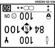
Work screen
Displays memorised engine speeds, PTO speed, actual wheel slip rate, lever mode, pedal mode (power or eco), self-propelled mode and SV1 and SV2 speeds.
Reverse shuttle sensitivity
Allows to adjust the response time when shifting direction of travel
The delay begins when the reverse shuttle lever is activated. If the delay is authorised, declutching takes place 5seconds after the lever is pulled. If not authorised, declutching takes place as soon as the lever is activated.
Pedal mode sensitivity screen
Used to adjust acceleration (+) and deceleration (-) sensitivity in pedal mode operation.
Fuel used screen
Consumption indicator:
-0 Quantity of fuel consumed since last reset.
-T: total fuel consumed. This value cannot be modified or reset.
General - Dyna VT Operation
To display from the previous screen
Press to enter the settings menu The symbol appears To set the required wheel slip percentage value
Allows to exit the settings screen
To display from the previous screen
Press to enter the menus
To select one of the displayed flow rate values or timing
To modify displayed flow rate values
When timing is selected, it is possible to display the type of timing (value or infinite)
To adjust the timing value
Allows to exit the settings screen and validate settings
Wheel slip screen (optional). Enables the max. allowable slip to be defined and displays the current wheel slip setting.
Joystick setting menu (1/2)
This menu allows to adjust the flow rate values of each spool valve controlled by the Joystick. If the Joystick is locked (padlock displayed on screen) press the armrest ON/OFF button.
Joystick setting menu (2/2)
This menu allows to activate or deactivate timing, and can be adjusted from 0 to 60 seconds or to infinite mode.
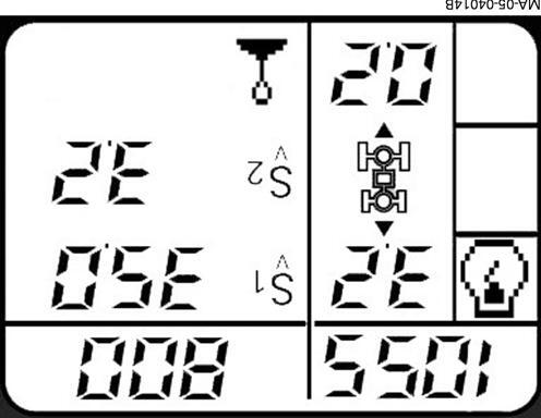
Headland 2 screen (if Datatronic 3 not installed)
Allows to activate the mode or validate the values
Used to shift from one line to another
Allows to set the seconds value of the displayed time
This menu allows to adjust the engine speed when changing linkage status (work or transport). The operating conditions are: -ON mode
-power shuttle lever out of neutral -tractor moving.
- When the linkage transport mode is selected, engine speed B is activated after the preset time.
- When the linkage working mode is selected, engine speed A is activated after the preset time.
To display from the previous screen
To activate or deactivate one of the two functions
To display from the previous screen
Press 5 seconds to switch from On to OFF
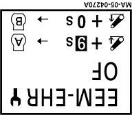
Headland 1 screen
This menu is used to vary the engine speed during activation of SV1 and SV2 memorised ground speeds.
Clutch - coupler screen
Displays whether the clutch- coupler fonction is on or off.
General - Dyna VT Operation
To display from the previous screen
To modify displayed linkage and spool valve flow rate values
To display from the previous screen
To display from the previous screen
To increase or decrease the value
To display from the previous screen
To increase or decrease the value
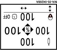
Linkage and spool valves menu
This menu allows to give priority to the auxiliary spool valves over the linkage, and vice versa.
Maximum linkage value: 100
Minimum spool valve value 0
Minimum linkage value: 20
Maximum spool valve value: 80
Error code screen
Displays all tractor error codes. Each error code is displayed for 4 seconds in a loop.
Brightness screen
Setting screen brightness
Contrast screen
Setting screen contrast
IMPORTANT : When the engine is stopped, all DOT MATRIX functions except the coupler function (CLUTCH) shift to OFF position.
05B01 - DYNAVT hydraulics
CONTENTS
A .Forward / Reverse high pressure relief valves.
B .Scavenging valve .
C .Control spool valve.
D .DYNAVT hydraulic tests
E .Service tools
DYNAVT hydraulics
Massey Ferguson
DYNAVT hydraulics
A . Forward / Reverse high pressure relief valves
General
The purpose of the high pressure relief valves is to regulate the increase in HP pressure. They protect the transmission elements (hydrostatic motors and pump).
4V5)
4V5)
A = Coupler and clutch functions inactive: Pressure identical in both chambers. The spool is held in closed position by the spring.
B = Coupler and clutch functions active: the pressure drop caused by the restrictor (nozzle) applies a force to
1
the spool that is more powerful than the force of the spring. The spool moves to the right, bringing PH into contact with ES (booster).
C = HP pressure is limited by the clutch and coupler spools.
Fig.
DYNAVT hydraulics
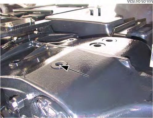
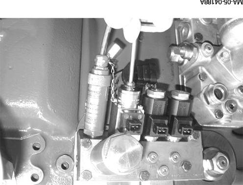
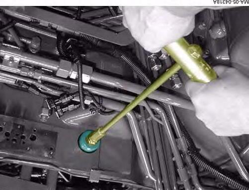
Replacing Forward / Reverse HP pressure relief valves
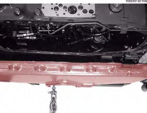
1. Drain the transmission oil
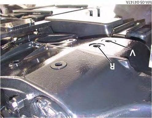
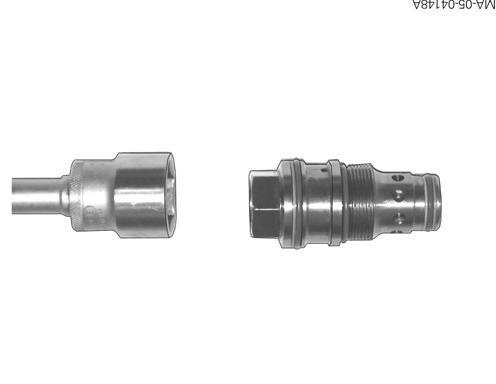
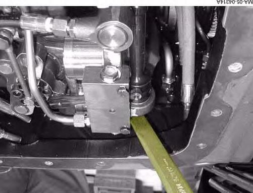
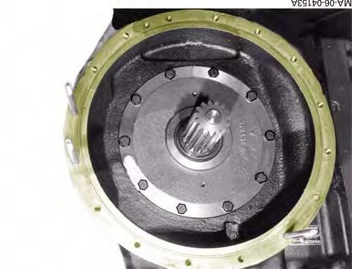
2. Loosen the 2 plugs with hexagonal heads located under the transmission housing. (Fig.2)
3. Use a wrench to remove the high pressure relief valves.
NOTE:
V = Forward high pressure relief valve
R = Reverse high pressure relief valve.
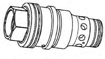
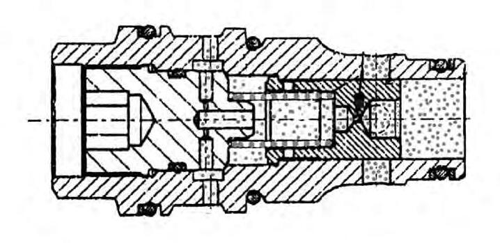
The high pressure relief valve is a controlled pressure relief valve (Fig.3)
Adjustment pressure when new: R500 + 20 bar.
Adjustment pressure after several hours: 480 ± 20 bar.
Only replace O’rings if they are damaged. Do not move the thrust collar. Tighten the pressure relief valve to a torque of
250 + 20 Nm
REMARK: Fill the transmission oil at an external filling station. (AGCO ref.: AGO2)
Fig. 2
Fig. 3
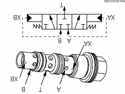
B . Scavenging valve
This valve allows to “flush” the oil in the hydrostatic loop.
Operation (Fig.4)
Pressure in A, B: max. 500 bar.
Pressure in T: max. 50 bar
Opening pressure: delta p = 7 bar between A and B
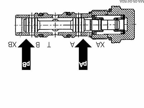
Transmission at neutral (Fig.5)
pA = pB, delta p < 7 bar
The spool is held in “middle” position by the spring. The two channels (A, B) are closed.
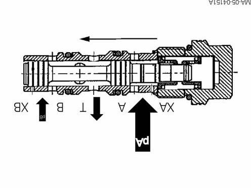
“Pulling” phase (Fig.6)
pA > pB, delta p > 7 bar
The spool moves upwards via control port XA. Channel B communicates with T. The hot oil coming from the low pressure side B can therefore be “flushed” and sent by the cooler via port T.
Fig. 4
Fig. 5
Fig. 6
CLICK HERE TO DOWNLOAD THE COMPLETE MANUAL
• Thank you very much for reading the preview of the manual.
• You can download the complete manual from: www.heydownloads.com by clicking the link below
• Please note: If there is no response to CLICKING the link, please download this PDF first and then click on it.
CLICK HERE TO DOWNLOAD THE
DYNAVT hydraulics
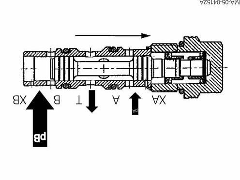
“Pushing” phase (Fig.7)
pA > pB, delta p > 7 bar
The spool moves downwards via control port XB. Channel A communicates with T. The hot oil coming from the low pressure side A can therefore be “flushed” and sent by the cooler via port T.
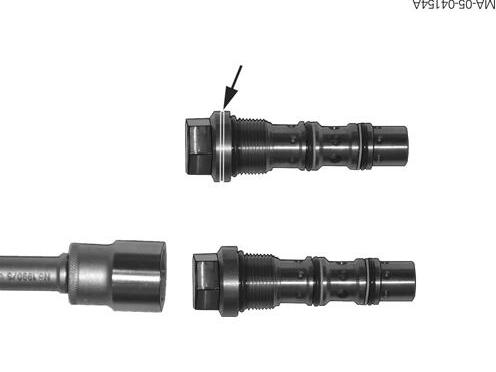
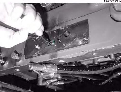
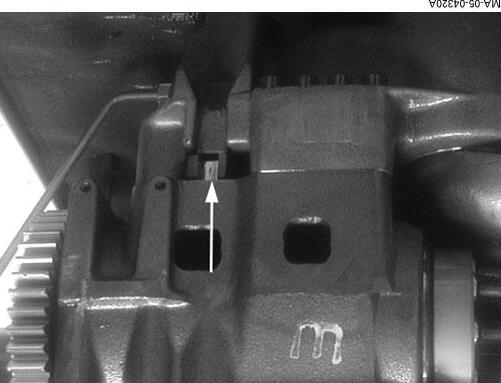
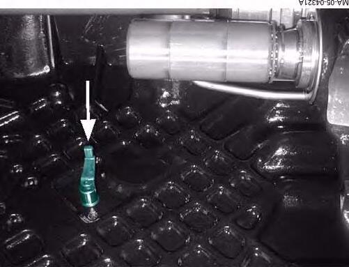
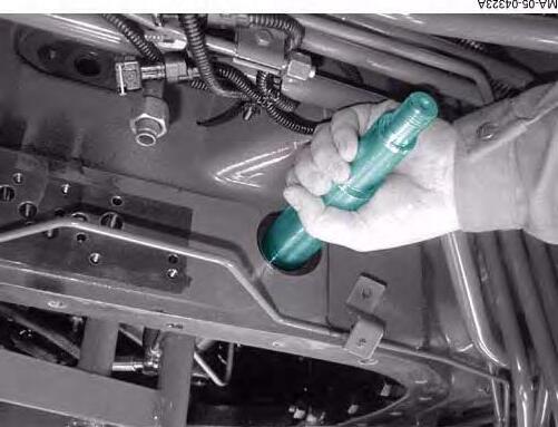
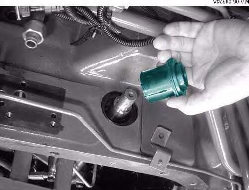
Disassembling the scavenging valve (Fig.8)
1. Drain the transmission oil.
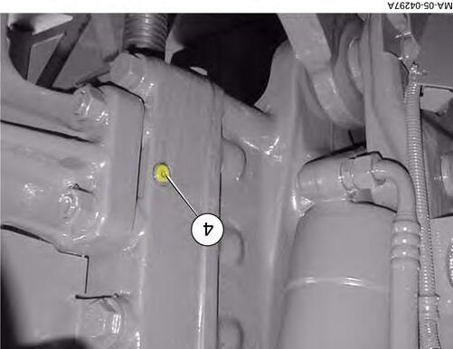
2. Remove the plug (arrow Fig.8) located under the transmission housing.
3. Use a wrench to remove the scavenging valve.
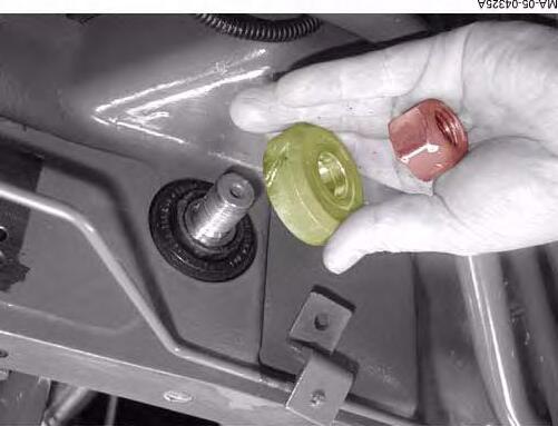
Fig.9 : Only replace O’rings if they are damaged. Do not move the thrust collars. The thrust collars are positioned facing each other. Tighten the scavenging valve to a torque of 200 + 10 Nm.
REMARK: The new scavenging valve with a seal groove (arrow Fig.9) is provided as a replacement. Tighten to the required torques:
250 + 20 Nm
4. Fill the transmission oil at an external filling station. (Ref. AGO2).
Fig. 7
Fig. 8
Fig. 9
DYNAVT hydraulics
C . Control spool valve
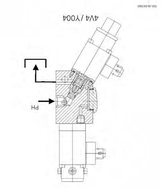
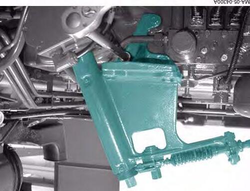
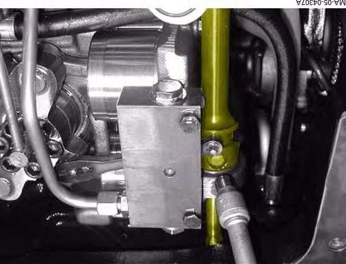
Pressure relief valve - 4V4 / Y004 coupler function
The coupler function valve (4V4) regulates the increase in hydrostatic pressure (PH) in proportion to the engine speed. Due to this component the coupler effect is simulated. The coupler function valve is fitted to the control block where the hydrostatic loop PH and tank return junction is located. If this junction is not closed, the pressure in the hydrostatic loop cannot increase, and the tractor does not reach its maximum pulling power. The junction between the hydrostatic loop PH and tank is closed by the coupler function valve (4V4).
Fig. 10
The coupler function valve is controlled by the electronic control unit. The strength of the current depends on the engine speed, and changes as shown by the following table:
Engine speed in rpmCurrent supplied at AMaximum PH in barRemark
800 00Transmission at neutral 800approx. 0.4678Transmission "active" 12001.23105 from 14001.71500
In order for the pressure to increase in the HP loop, it is necessary to maintain the electrical supply and the tightness of the coupler function valve.
DYNAVT hydraulics
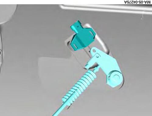
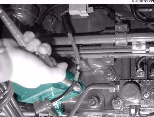
The tighness of the valve seal can be ensured by a mechanical lock mechanism.
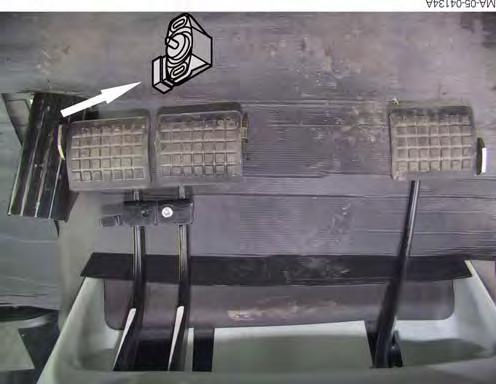
5. Move the control lever (see arrow Fig.11)
6. Or tighten the internal Allen screw.
Fig. 11
Fig. 12
DYNAVT hydraulics
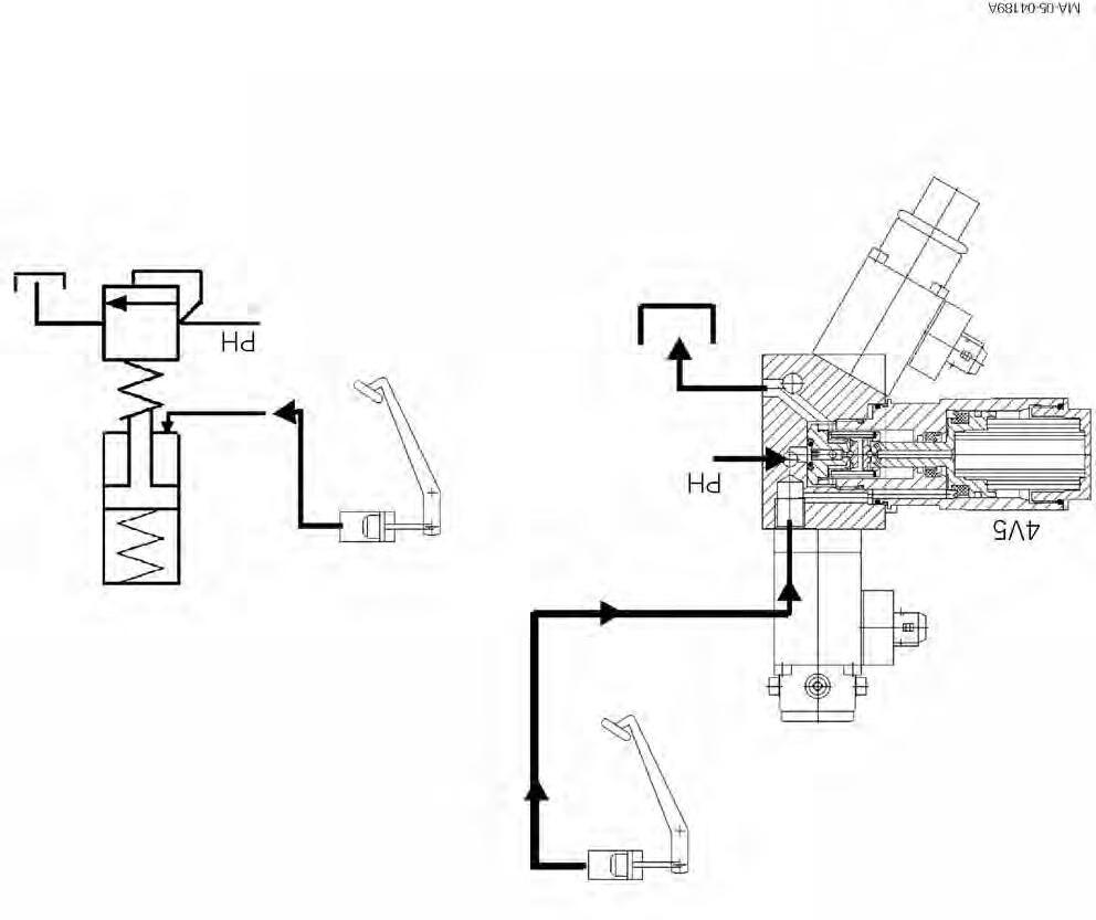
Pressure relief valve 4V5 - clutch function
The clutch function valve is fitted to the control block where the PH hydrostatic loop and tank return junction is located. The clutch function valve also allows to limit the maximum pressure PH in the 500 bar (± 20 bar) hydrostatic loop. Due to the clutch function valve, when the clutch pedal is not activated, the junction between the hydrostatic loop and tank return is closed. By moving the clutch pedal, the clutch function valve opens and the hydrostatic loop communicates with the
tank return channel. This results in a drop in pressure (interruption of the pulling effort) in the hydrostatic loop, proportional to how far in the clutch pedal is pressed (comparable to a mechanical forward clutch). Clutch pedal pressed in fully, High pressure PH = 0bar
The maximum pressure can be achieved in the hydrostatic loop only when the clutch valve (4V5) is functioning perfectly.
13
Fig.
DYNAVT hydraulics
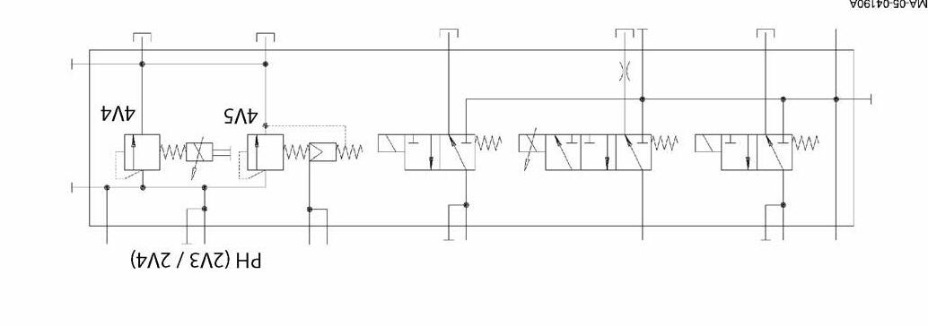
Checking the control block
If maximum pressure is not reached when measuring the HP pressure, the transmission module may be defective, but it is also possible that the internal seal tightness of the control block is the cause of the problem. To be sure that it is necessary to disassemble the transmission module, it is recommended to first check the seal tightness of the spool valve block (transmission control).
The pressure in the hydrostatic loop can only increase if the pressure relief valve seals are tight.
-Coupler function (4V4 / Y004)
-Clutch function (4V5)
When the following conditions are met, the coupler function valve allows the pressure in the hydrostatic loop to increase:
-Engine speed higher than 1400 rpm (PWM - Signal)
-Limp home mode activated
-Valve locked mechanically (tighten the internal Allen screw or move the lever).
The clutch function valve is closed (increase in HP pressure possible) when the clutch pedal is not activated.
The tightness of the 2 pressure relief valves (4V4 / 4V5) can be controlled by the T union.
Fig. 14
Fig. 15
Checking the hydrostatic loop in the control block
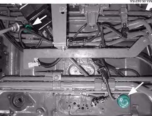
DANGER: Chock the tractor (HP pressure measurement).
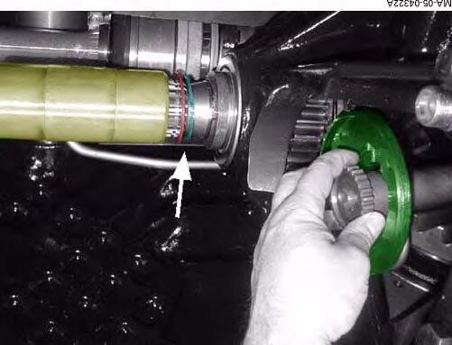
7. Remove the right-hand rear wheel and its protective guard located behind it
8. Remove the T union.
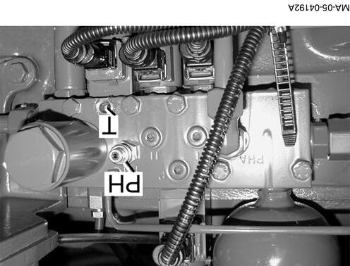
9. Fit a test pressure gauge to measure pressures higher than 500 bar at the PH union.
Checking procedure:
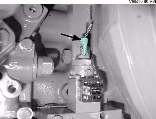
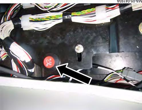
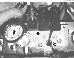
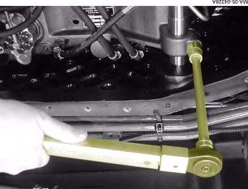
10. Start the engine.
11. Activate the limp home mode by pressing in the clutch pedal fully and pressing on the button (Fig.17).
12. Apply the handbrake.
Fig. 16
Fig. 17
DYNAVT hydraulics
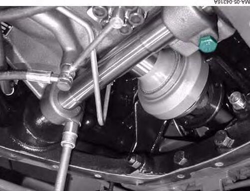
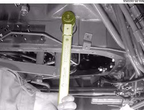
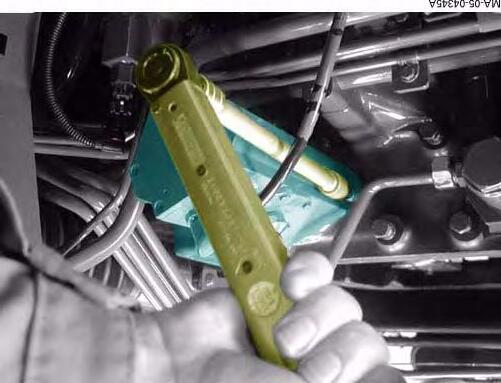
13. Use the limp home mode lever to start the transmission (Fig.18).
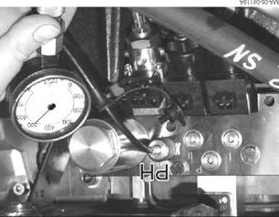
PHT union
250 barNo oil flow to the T union
250 barOil flows from the T union
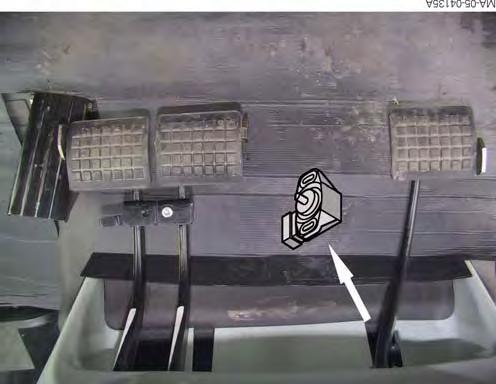
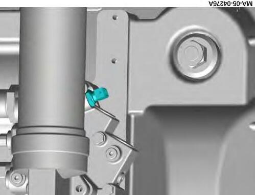
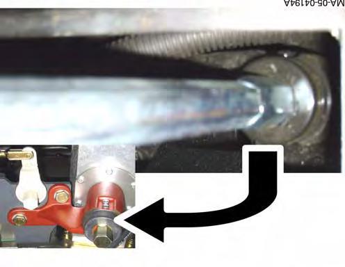
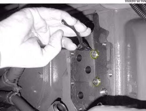
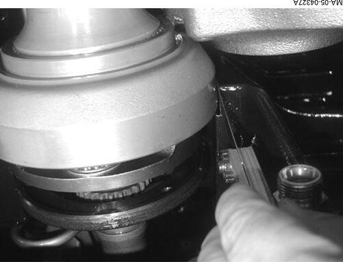
Checking the clutch function valve (4V4)
14. Mechanically lock the valve (tighten the internal Allen screw (Fig.12) or move the lever (Fig.11))
PHT union
250 barOil flows from the T union
500 barOil flows from the T union, but the pressure is not constant
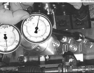
M8IIHare range shifting pressureM19 Reverse position HP pressure
M9PHHigh pressure (HP)M21 Front PTO clutch pressure
M10PHA Rear axle beam and braking system pressure M22T Oil leak on clutch function spool valve / coupler function solenoid valve
Fig.
DYNAVT hydraulics
Precautions to be taken during the pressure measurements:
The oil temperature must be between 35 and 45°C
IMPORTANT: When measuring the transmission pressure, raise all wheels of the tractor to prevent accidents.
1. Set transmission ratio (Hi/Lo) to speed of 0.
2. Release the handbrake.
3. Engage the front axle.
4. Differential lock and PTO clutch are not engaged.
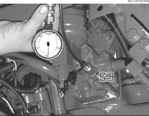
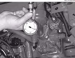
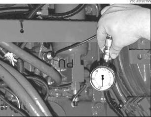
On right-hand side, in the middle of the tractor:
5. Remove right-hand rear wheel and its protective guard.
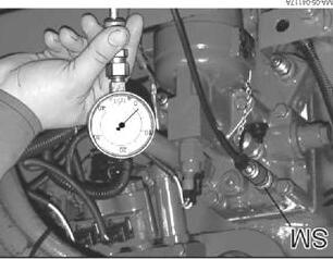
6. Connect a test pressure gauge. Measure the pressures set out below according to the different engine speeds (see settings table below)
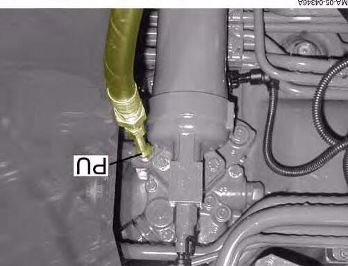
-PU Pressure (M5). Pressure measuring point located between the service pump and the pressure filter (Fig.19)
-P Pressure (M6) System pressure downstream of pressure filter (Fig.19).
-ES booster pressure (Fig.19)
-AS flushing or discharge pressure
-SM transmission lubricating pressure (Fig.19).
Set values for pressure measurement (in bar)
High pressure (HP) measurements
DANGER: High pressure measurements must never exceed a maximum of 5 seconds, to prevent the oil from heating.
Preliminary operations:
Engage hare range and set the starting speed to maximum, or transmission to limp home mode (do not turn the control unit by more than 15° in order to avoid heating the oil).
DYNAVT hydraulics
NOTE: Load the hydrostatic loop at maximum for 5 seconds before taking the following measurements.
Shifting pressure measurements
NOTE: Alternately supply solenoid valves 1 (4V1) and 2 (4V2) with a 12 V (DC) supply
DYNAVT hydraulics
Rear PTO, differential lock and front axle clutch solenoid valve measurement
NOTE: The unit is located on the rear axle housing, behind the spool valves. Access is limited, so great care must be taken.
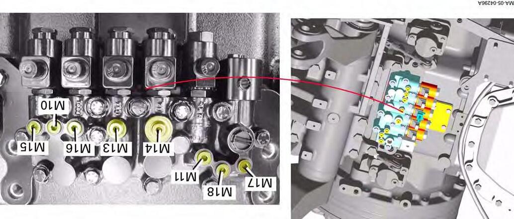
Measuring points
Description
M10Rear axle beam, brakes and front PTO system pressure
M11Rear PTO clutch
M13750 rpm PTO selector pressure
M14Front axle clutch
M15Differential lock
M161000 rpm PTO selector pressure
M17Braking system pressure
M18Rear axle beam lubricating pressure
Fig. 20
CLICK HERE TO DOWNLOAD THE COMPLETE MANUAL
• Thank you very much for reading the preview of the manual.
• You can download the complete manual from: www.heydownloads.com by clicking the link below
• Please note: If there is no response to CLICKING the link, please download this PDF first and then click on it.
CLICK HERE TO DOWNLOAD THE
NOTE: Run the engine at 1200 rpm. Simultaneously check the pressure at unions M10 and M18 (SM).
DYNAVT hydraulics
In order to check the rear PTO, it is also possible to measure pressure levels at the unions located at the rear right- and left-hand sides of the PTO housing.
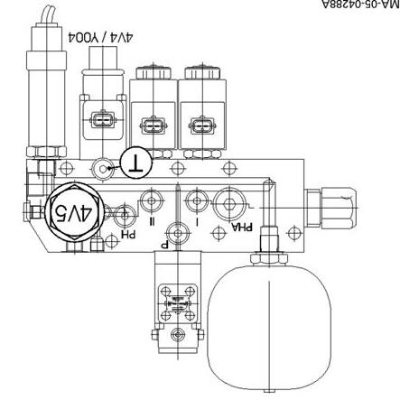
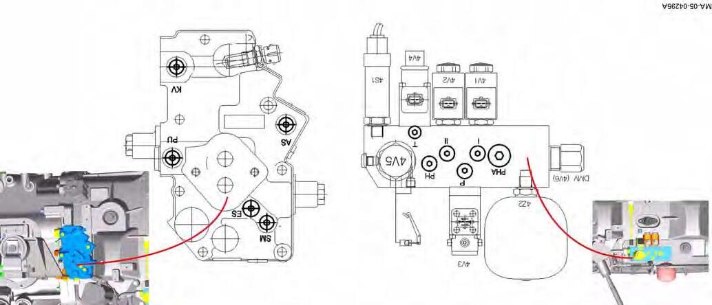
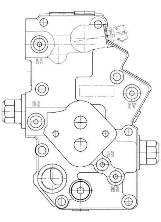
Diagram showing the pressure check points on the valve block
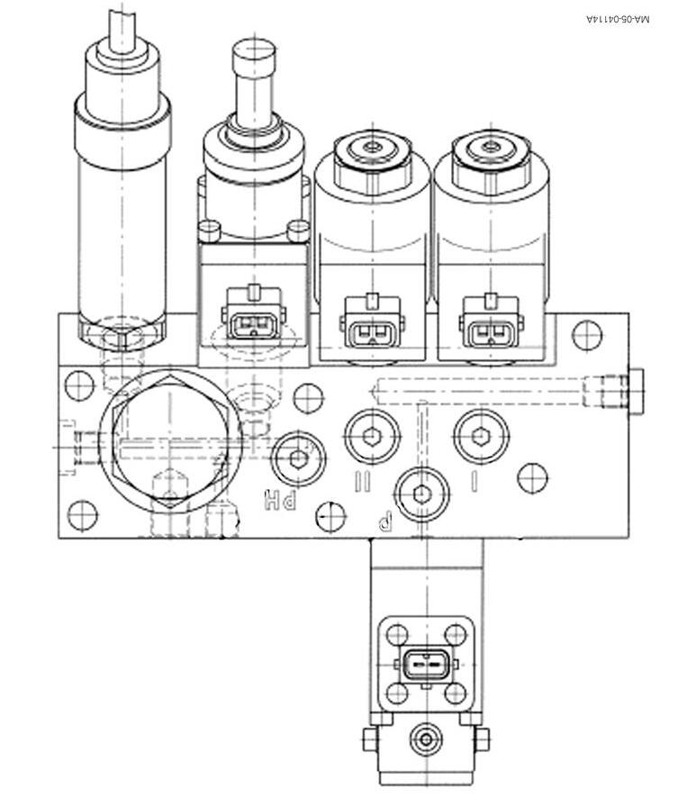
DYNAVT hydraulics
Service pump P
Speed limitation solenoid valve
Hare/Tortoise supply pressure
Tortoise range Hare range Solenoid valves
High pressure PH
Coupler function solenoid valve
Clutch function controlled valve
HP Pressure sensor
Fig. 23
Valve housing with test connections
Lubricating pressure (SM)
Booster valve (6.5 b)
Flushing valve (6 b)
Flushing pressure (AS)
Booster pressure (ES)
temperature (°C) Lubricating pressure valve (6.5 b)
Service pump relief valve (50 b)
Oil cooler bypass valve
Service pressure (PU)
Fig. 24
DYNAVT hydraulics
E . Service tools
1. Tool available in AGCO network
AG02 - External filling station (Fig.25)
MA-05-04158A
Fig. 25
05C01 - Replacing the DYNAVT unit
CONTENTS
A.Desassembling the DynaVT module.
B.Assembling the DynaVT module.
C.Service tools.
3
Massey Ferguson
A . Desassembling the DynaVT module
Preliminary operations:
1. Drain the transmission oil (approx. 65l.)
2. Disassemble the cab.
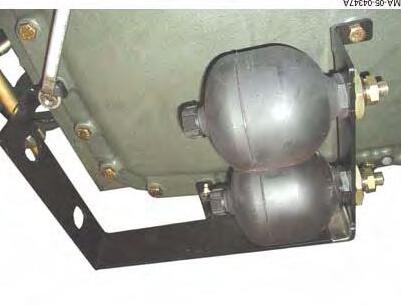
DANGER: Before disconnecting the pipes, it is necessary to release the pressure in the brake accumulator by pumping on the pedals.
3. Remove the unions after emptying, taking the precautions necessary to prevent any dirty particles from entering the air conditioning circuit
ADVICE: It is recommended to raise the cab slightly before splitting it.
4. Pinch the heating pipes closed to avoid draining the circuit.
5. Attach the cab to a suitable hoisting system and lift it off.
CAUTION: Take care not to damage the roof cap.
6. Disconnect the cables and hydraulic unions, taking care to mark them.
7. Remove the spool valve block.
CAUTION: Mark all parts at disassembly.
8. Hoist and remove the cab.
9. Remove the accumulator assembly.
Fig.
Replacing the DYNAVT unit
10. Move the range selector to neutral.
11. Take off the limp home console.
12. Disconnect the connector.
13. Remove the control unit.
14. Take off the pressure filter housing. Recover the oil that flows out.
Fig. 2
Fig. 3
Fig. 4
15. Remove the electrical connectors and hydraulic pipes.
16. Remove the valve block.
17. Disconnect the connectors, the clutch vent line and the hydraulic pipes.
18. Remove the valve block.
19. Disconnect the electrical connector and remove the summing shaft sensor.
Replacing the DYNAVT unit
Fig. 5
Fig. 6
Fig. 7
CLICK HERE TO DOWNLOAD THE COMPLETE MANUAL
• Thank you very much for reading the preview of the manual.
• You can download the complete manual from: www.heydownloads.com by clicking the link below
• Please note: If there is no response to CLICKING the link, please download this PDF first and then click on it.
CLICK HERE TO DOWNLOAD THE
Replacing the DYNAVT unit
20. Remove the pipe support and strapping.
21. Unscrew the cover screws.
22. Raise the cover using the M10 eye-bolt.
23. Unscrew the locking screw and take out the control shaft.
24. Remove the retainer circlips and push the hoses inwards.
25. Disconnect the high pressure hoses.
Fig. 8
Fig. 9
Fig. 10
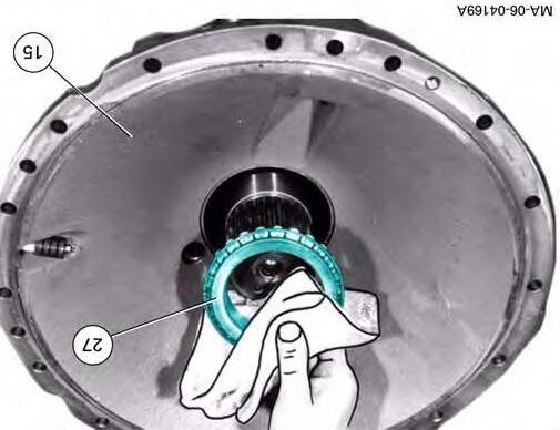
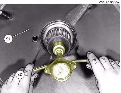
26. Remove the 3 circlips and push the hoses inwards.
27. Remove the hydraulic pipes (supply pressure of auxiliary functions).
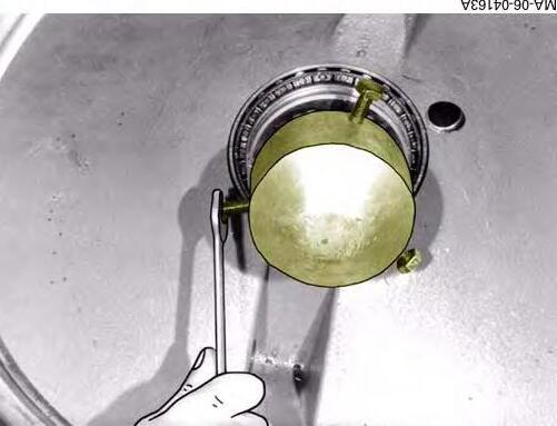
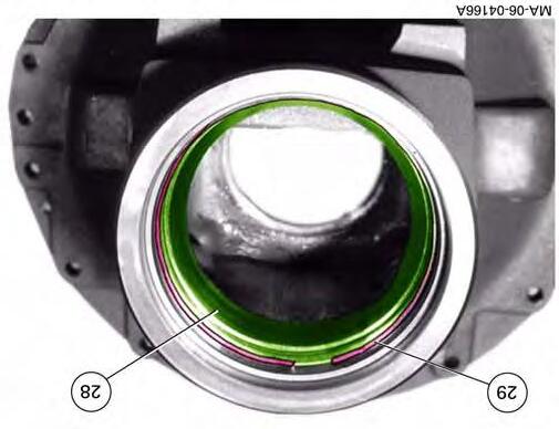
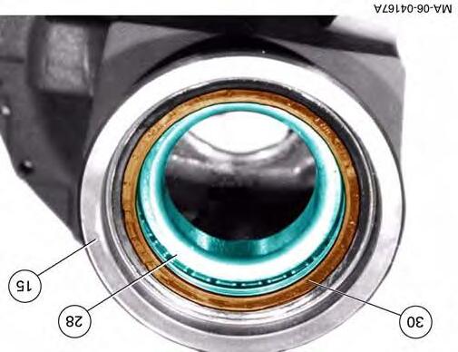
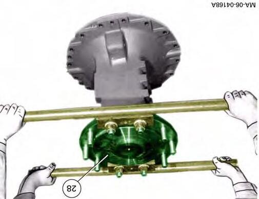
28. Take off the drive shaft circlip.
29. Push the shaft backwards.
Fig. 11
Fig. 12
Fig. 13
Replacing the DYNAVT unit
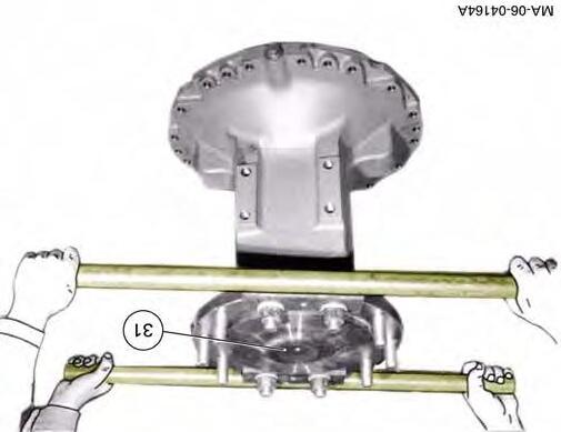
30. Unscrew the 3 M8 screws from the planet carrier.
31. Push the shaft backwards.
32. Remove the drive pinion circlip.
33. Push the circlip, washer and socket towards the drive pinion, as indicated by the arrow.
34. Swivel the hydrostatic motors and the pump inwards using a lever.
Massey Ferguson
Fig. 14
Fig. 15
Fig. 16
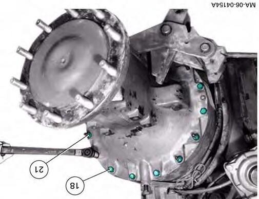
35. Unscrew the 2 nuts (see arrows) located on the left and right.
Replacing the DYNAVT
36. Unscrew the upper M12 locking screw.
37. On the inner surface of the gearbox housing, unscrew the 2 closing plugs.
38. Recover the oil.
39. Unscrew the 2 locking screws on the lower shaft.
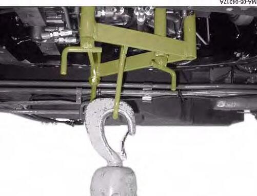
40. Install lifting tackle.
41. Slightly raise the hydraulic module, ensuring the lifting tackle remains under a certain level of tension.
Fig. 17
Fig. 18
Fig. 19
Replacing the DYNAVT unit
42. Using a slide hammer puller on the M20 threads, extract the flexible suspension shafts.
43. Take the transmission module carefully out of the gearbox housing using the lifting tackle.
44. Stay alert in case other parts move.
DANGER: Do not stand under heavy loads.
Fig. 20
Fig. 21
B . Assembling the
DynaVT module
CAUTION: Before reassembling, all components, mating faces and grooves must be clean. Any rust, mud or water must be removed.
45. Raise the transmission block with lifting tackle, after securing it.
46. Move the range selector (Hare / Tortoise) (arrow Fig.22) to “Neutral” (middle position).
47. Clean any oil or seal fragments from the transmission housing mating face.
48. Move the range selector finger (see arrow) to “Neutral”. (middle position).
If necessary:
49. Fit the circlip and washer on the shoulder of the drive pinion.
50. Push the socket onto the drive pinion.
51. Fit the flange on the link shaft (PTO drive) and fit the link shaft.
Fig. 22
Fig. 23
Fig. 24
Replacing the DYNAVT unit
52. Fit the transmission module in the transmission housing. Stay alert in case other parts move.
53. Fit the two shafts into the bores of the transmission housing and transmission module.
NOTE: The two shafts are of different lengths; the longer one is fitted at the base of the gearbox.
54. Check the sockets (flexible) for wear, and fit new sockets if necessary.
55. Insert the sockets home into the bores.
56. Fit the ring, with the bore turned towards the flexible socket.
57. Tighten the M20 nut.
58. Carry out the same assembly operation on the three other threads.
Fig. 25
Fig. 26
Fig. 27
59. Tighten the four M20 nuts to a torque of:
Replacing the DYNAVT unit
NOTE: When tightening, hold the opposite nut still.
60. Unhook the lifting tackle.
61. Install a planet gear of the power transmission epicyclic gear train turned upwards.
62. Centre the transmission module. The distance between the ring gear and the transmission housing must be identical on either side.
63. Tighten the 4 locking screws to a torque of:
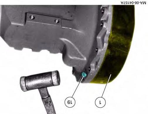
64. Install 2 closing plugs fitted with new seals under the transmission housing.
65. Test the correct operating of Hare / Tortoise range shifting (check finger positioning).
Fig. 28
Fig. 29
Fig. 30
Replacing the DYNAVT unit
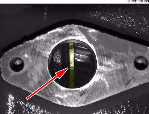
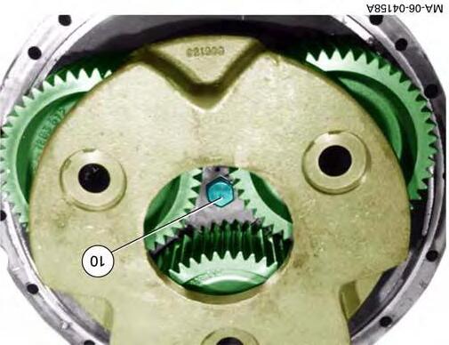
66. Turn the transmission module until a tooth of the disc, intended for the Hall sensor, can be seen at the middle of the bore. (arrow Fig.31).
67. Smear the mating face of the Hall sensor with sealing product (ref. X903.050.553) (non-hardening) and insert the sensor into its housing.
68. Tighten the attachment screws to a torque of:
69. Reconnect the electrical connector.
NOTE: If the Hall sensor is being reused, insert 2 strips of paper 0.9 mm thick into the Hall sensor groove (these strips ensure centring).
70. Swivel the hydrostatic motors to their stop (45°).
25 Nm
Fig. 31
Fig. 32
Fig. 33
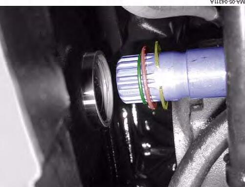
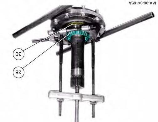
71. Pull the drive pinion socket forwards to release the groove from the circlip. Insert the circlip into the groove.
NOTE: If the socket does not engage, chock a front wheel and turn it until the socket is engaged.
72. Fit the flange on the epicyclic gear train. Tighten the M8 screws to a torque of:
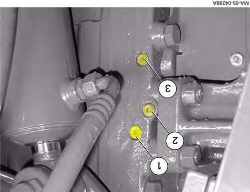
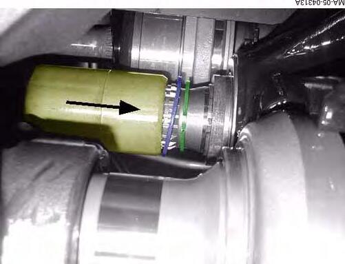
73. Insert the hydraulic hoses into the bores on the front right-hand side of the transmission housing.
74. Secure the hoses using circlips (opening facing downwards).
-1 = short blue hose (flushing)
-2 = long blue hose (boosting)
-3 = black hose (lubricating)
Fig. 34
Fig. 35
Fig. 36
Replacing the DYNAVT unit
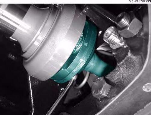
At the front on top of the transmission housing:
75. Fit the ring in the groove of the shaft.
76. Push the shaft forwards. Install the washer.
77. Fit the circlip in the pinion groove.
78. Fit the hydraulic pipe (supply pressure of auxiliary functions).
79. Insert the pressure pipes in the bores in the right-hand side of the transmission housing.
-1 = supply pressure hydraulic hose
-2 = Hare range shifting
-3 = ground speed limiting
-4 = Tortoise range shifting
-5 = Regulating valves (tilting)
-6 = High pressure for forward clutch and coupler function.
Fig. 37
Fig. 38
Fig. 39
CLICK HERE TO DOWNLOAD THE COMPLETE MANUAL
• Thank you very much for reading the preview of the manual.
• You can download the complete manual from: www.heydownloads.com by clicking the link below
• Please note: If there is no response to CLICKING the link, please download this PDF first and then click on it.
CLICK HERE TO DOWNLOAD THE
80. Attach the hydraulic pipes using circlips.
Replacing the DYNAVT unit
81. Screw 2 M8 threaded rods into the transmission housing.
82. Fit new O’rings.
83. Stick seals in the block using grease.
84. Fit the control block.
85. Tighten the attachment screw (from the inside to the outside) to a torque of:
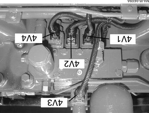
86. Connect the connectors, clutch function bleed pipe and hydraulic pipes.
-4V1 = Hare range solenoid valve
-4V2 = Tortoise range solenoid valve
-4V4 = Coupler function solenoid valve
-4V3 = Ground speed limiting solenoid valve
25 Nm
Fig. 40
Fig. 41
Fig. 42
Replacing the DYNAVT unit
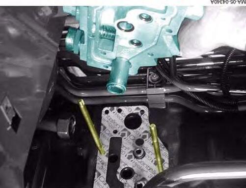
87. Screw 2 M8 threaded rods into the transmission housing. Fit new seals.
88. Fit new seals with grease in the valve block.
89. Install the block and tighten the screws, starting with the inside screws to the following torque:
25 Nm
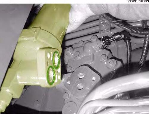
90. Connect the connectors and hydraulic pipes.
91. Fit new O’rings with grease and attach the pressure filter, tightening the screws to the following torque:
25 Nm
92. Connect the connector.
93. If necessary, smear the lip seal with a mixture of white spirit and water (1:1) and fit it home. Fill the lip seals 2/3 full with grease.
94. Fit the control shaft.
Fig. 43
Fig. 44
Fig. 45
95. Turn the shaft until the locking screw thread can be seen.
NOTE: Smear the thread of the Allen screw with plastic binder (LOCTITE) (Ref. X 903.050.084) and tighten the screw to the following torque:
Replacing the DYNAVT unit
96. Fit the intermediate coupler with the two bosses (see arrows) pointing to the control unit.
97. Fit the pre-assembled control unit on the transmission housing.
98. Tighten the M8 cylindrical screws to a torque of:
99. Reconnect the electrical
connector.
Fig. 46
Fig. 47
Fig. 48
Replacing the DYNAVT unit
100.Unscrew the plug marked PU.
101.Connect the filling station (Fig.49).
NOTE: Using the external filling station it is possible to avoid dry operation of the hydrostatic pump and hydrostatic motor.
102.Be sure to comply with the oil quantity and type (see chapter 1).
NOTE: During the filling process, swivel the hydrostatic pumps and motors. Ensure the hydraulic unions are completely sealed. Fill the transmission oil with a filling station.
103.Smear the mating face of the transmission housing with sealing product (Ref. X903.050.074).
104.Fit the cover.
105.Tighten the M12 screws to a torque of:
106.Fit the pipe support.
107.Refit the cab.
108.Reassemble all hydraulic unions as marked at disassembly.
109.Refit the spool valve support.
110.Reconnect all electrical connections as marked at disassembly.
111.Connect the heating pipes.
112.Connect the air conditioning pipes.
113.Check the levels of the various liquids.
MA-05-04158A
Fig. 49
Fig. 50
C . Service tools
1. Tool available in AGCO network
AG02 - External filling station (Fig.51)
MA-05-04158A
Fig. 51
Massey Ferguson
06- Rear axle
CONTENTS
06B01-Final drive units
06C01-Braking unit
Massey Ferguson
Massey Ferguson
06B01 - Final drive units
CONTENTS
A .Généralités
B .Removing a rear axle drive
C .Refitting a rear axle drive
D .Disassembling
E .Reassembling
F .Service tools
Massey Ferguson
A . Généralités
The rear axle final drive units have a separate lubrication system to the rear axle. Tightness between the two parts is ensured by a double lip seal.
The brakes are multidisc (6 discs with friction lining and 6 intermediate plates per final drive unit).
They operate via a braking mechanism activated by a brake cylinder and a control lever.
N.m
N.m
N.m
Adjusting the bearings:
Preload the taper roller bearings (A, B) using shim (C) so that the rotational resistance torque increases from 4 to 6 Nm (without spi seal).
Planet carrier axial clearance:
Specified clearance: 0.2 to 0.5 mm (there must be axial clearance!)
Fig. 1
CLICK HERE TO DOWNLOAD THE COMPLETE MANUAL
• Thank you very much for reading the preview of the manual.
• You can download the complete manual from: www.heydownloads.com by clicking the link below
• Please note: If there is no response to CLICKING the link, please download this PDF first and then click on it.
CLICK HERE TO DOWNLOAD THE
Massey Ferguson
Fig. 2
Pos.
1Ring gear
2Planet gear
3Pin
4Circlip
20Threaded rod M12 x 165-10.9
21Nut M12-10
23Locking screw M30 x 1.5
24Joint d’étanchéité
5Needle bearing cage 25Ring
10Allen screw 26Shim
11Plate
27Taper roller bearing
12Pin 28Taper roller bearing
14Planet carrier 29Snap ring
15Drive unit housing 30Spi seal
16Joint d’étanchéité
17Magnetic plug
31Rear axle shaft
32Wheel stud
18Allen screw M12 x 160-10.935Shaft
Massey Ferguson
Fig. 3
Pos. Description
1Ring gear
21Nut M12-10
2Planet gear 23Locking screw M30 x 1.5
3Pin
24Joint d’étanchéité
4Circlip 25Ring
5Needle bearing cage 26Shim
10Allen screw
27Taper roller bearing
11Plate 28Taper roller bearing
12Pin 29O’ring
14Planet carrier 30Spi seal
15Drive unit housing 31Rear axle shaft
16Joint d’étanchéité 33O’ring
17Magnetic plug 35Shaft
18Allen screw M12 x 160-10.940Spacer
19Cylindrical screw 41Cover
20Threaded rod M12-165 -10.942Allen screw
Page left blank intentionally
Massey Ferguson
Cross-section of a drive unit
Massey
MA-06-04210A
Fig. 4
Page left blank intentionally
B . Removing a rear axle drive unit
The following must be carried out before disassembling
1. Drain the transmission.
2. Drain the drive units.
3. It is necessary to remove a cab support to extract a drive unit.
4. Remove the rear wheels and securely chock the tractor.
5. Remove obstructive protective guards.
6. Remove the hitch stabiliser (Arrow Fig.1).
7. Remove cab suspension supports ( Fig.2)
8. Remove other parts which might obstruct disassembly.
Fig. 1
Fig. 2
Final drive units
9. Support the drive unit in a secure manner using a suitable lifting device. Remove the drive unit housing attachment parts (Fig.3).
10. In place of the 2 two CHC screws, screw in 2 threaded screws to release the rear axle drive unit.
11. Remove the drive unit.
Fig. 3
Fig. 4
C . Refitting a rear axle drive unit
12. Clean the mating surface between the rear axle and the drive unit, and smear with a sealing product (Ref. X903-050-074).
13. Fit the drive unit with a suitable lifting device.
14. Fit and tighten diametrically opposed screws (18 and 21) to a torque of:
15. Carry out operations (6 to 10) in reverse order.
Fig. 5
Fig. 6
Fig. 7
Final drive units
D . Disassembling a rear axle drive unit
NOTE: The operations described apply to a standard drive unit. Adjustment and reconditioning are identical for long shaft drive units.
Preliminary operations:
Remove the rear axle drive unit (see § B)
16. Unscrew the cylindrical screws (19) by about 10mm and knock out the ring gear (1) with a mallet.
17. Remove ring gear (1).
18. Unscrew the Allen screw (10) and remove the planet carrier.
IMPORTANT: The screw (10) is stuck at assembly.
If necessary:
19. Remove the circlips (4).
20. Take out the pins (3).
21. Remove the planet gears (2)
22. Replace any defective parts.
Fig. 8
Fig. 9
Fig. 10
23. Fit the planet gears (2).
24. Fit the pins (3).
25. Fit the circlips (4).
Preloading the axle shaft:
26. Fit one or two shims (ref. X 534.739.501) (individual thickness: 1 mm) on the bearing of the axle shaft (31).
27. Fit the planet carrier.
NOTE: If no shims are available, a locally made tightening socket can be used to preload the axle shaft bearing.
28. Pretighten the journal of the axle shaft using the Allen screw (10).
29. Remove the planet carrier (14) again.
IMPORTANT: Do not turn the axle shaft (31).
Fig. 11
Fig. 12
Fig. 13
CLICK HERE TO DOWNLOAD THE COMPLETE MANUAL
• Thank you very much for reading the preview of the manual.
• You can download the complete manual from: www.heydownloads.com by clicking the link below
• Please note: If there is no response to CLICKING the link, please download this PDF first and then click on it.
CLICK HERE TO DOWNLOAD THE
Final drive units
30. Take out the split ring (25) from the groove in the axle shaft (31).
31. Take off the shims.
32. Take out the cotter pin.
33. Insert the protective plug X 899.980.157 on the end of the axle shaft.
34. Fit the planet carrier.
35. Fit a locally made mounting handle (see Fig.16) to the axle shaft (31).
36. Drive out the axle shaft (31) onto a metal block.
Fig. 14
Fig. 15
Fig. 16
37. Take the internal ring out of the taper roller bearing (28) using extractor X 899.980.159.
38. Next, extract the spi seal (30).
Fig. 17
Final drive units
E . Reassembling a rear axle drive unit
Important: Before reassembling, all components, mating faces and grooves must be clean. Any rust, mud or water must be removed.
If necessary:
39. Fit home the external ring of the taper roller bearing (28).
40. Fit the snap ring (29) into the groove.
41. On the opposite side, fit home the external ring of the taper roller bearing.
42. Heat the internal ring of the taper roller bearing (28) to approximately 80°C and install it in the drive unit housing (15).
43. Smear the outside of the new spi seal (30) with sealing product X 903.051.711, clean the inside with a mixture of white spirit and water (1:1) and fit it home.
44. Before the internal ring cools, fit home the shaft (31) using locally made handles (see Fig.20).
Fig. 18
Fig. 19
Fig. 20
45. Turn the housing (15) upside down.
46. Heat the internal ring of the taper roller bearing (27) to approximately 80°C and fit it home.
47. Smear the axle shaft journal with transmission oil.
48. Support the housing (15). The axle shaft journal clearance should be minimal.
49. Fit the torque gauge (ref. X 899.980.150).
50. Measure and note down the rotational strength of the sealing ring. Example: 5.0 Nm
51. Select a thickness of shims (26) to allow tight assembly of the split ring (25).
NOTE: Wherever possible, fit shims (26) so that the shim 1.0 mm thick is on the split ring (25) side.
Fig. 21
Fig. 22
Fig. 23
Final drive units
52. Fit two shims (Ref. X 534.739.501) (individual thickness: 1 mm) on the axle shaft (31).
53. Refit the planet carrier and tighten home. The resistance of the bearing at the axle shaft journal should increase slightly.
NOTE: If bearing resistance does not increase, take off the planet carrier again and fit new shims (26) under the split ring (25), see Fig.23, then preload the axle shaft journal again.
54. Tap the journal on either side with a mallet to reduce the load on it.
55. Remove the planet carrier again.
56. Select the thickness of shims (26) to allow assembly of the split ring (25) by tapping lightly with a hammer.
57. Fit the cotter pin (ref. 12) in the axle shaft (31).
58. Smear the thread of the Allen screw (10) with plastic binder (Ref. W 903.050.084) and tighten to the following torque:
59. Tap the journal on either side with a mallet to reduce the load on it.
Fig. 24
Fig. 25
Fig. 26
CLICK HERE TO DOWNLOAD THE COMPLETE MANUAL
• Thank you very much for reading the preview of the manual.
• You can download the complete manual from: www.heydownloads.com by clicking the link below
• Please note: If there is no response to CLICKING the link, please download this PDF first and then click on it.