13 minute read
500 Hours Service

from Daewoo Doosan ADT MT25 MT26 MT31 MT36 MT41 Operation and Maintenance Manual MX519828 - PDF DOWNLOAD

1
3 2
500 Hours Service Maintenance to be performed every 500 hours of operation.
1. Engine
1.1. Change oil 1*
If the dump truck is used for par ticulary demanding operation, especially in a dusty environment or if the deposits in the centrifugal cleaner are thicker than 20 mm:
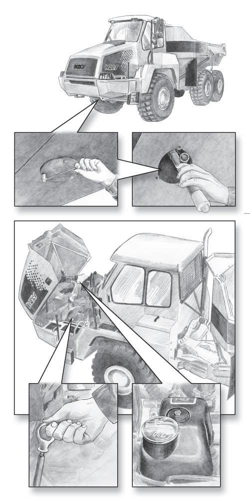
Change oil more often. 1. Remove the cap on the drain plug, install the draining hose (tool kit) and drain the oil when the engine is hot. Access through the drain hole in engine bottom guard (1). 2. When all oil is drained, remove the draining hose and re-install the cap. 4. Reinstall the cover for drain hole in engine bottom guard. 5. Fill oil through fi ller (2). Do not overfi ll! 6. Check oil level on dip stick (3).
CAUTION
The oil may be hot! Wear protective gloves and eye protection.
500 Hours Service Maintenance to be performed every 500 hours of operation.
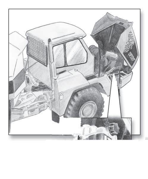
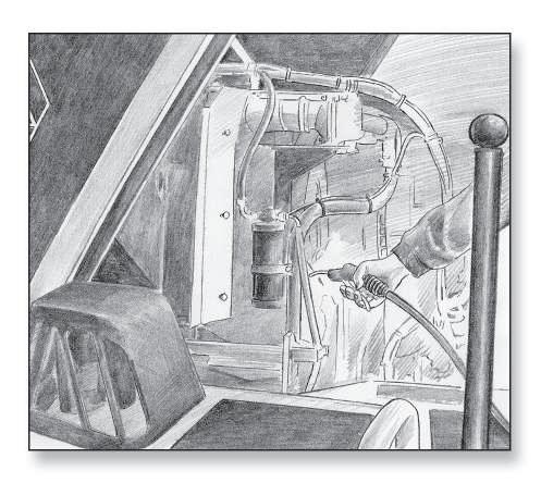
1.2. Clean centrifugal cleaner 2* (at the same time as oil change, item 1.1)
1. Clean the cover. Unscrew the nut and remove cover.
CAUTION
Open the cover with care. The oil and inner parts may be hot!
2. Lift out the rotor assembly and loosen the nut for the rotor cover three turns.
500 Hours Service Maintenance to be performed every 500 hours of operation.
3. If the nut sticks:
Secure the nut, absolutely not the rotor, in a vice and turn the rotor three turns by hand or using a screwdriver.
4. Gently tap the nut with the hand or with a plastic hammer to separate the rotor from bottom plate.
5. Undo the nut and remove the rotor cover. 6. Carefully prise the strainer loose from the bottom plate.
7. Scrape off the deposits from the inside of rotor cover. • If there are no deposits, this shows that the cleaner is not working. • Clean more frequently if deposits are thicker than 20 mm. 8. Clean all parts in diesel fuel.
500 Hours Service Maintenance to be performed every 500 hours of operation.
9. Place the O-ring in position in the rotor cover. • The O-ring must not be damaged. Change if necessary.
10. Assemble the rotor.
11. Tighten rotor nut fi rmly by hand.
12. Reinstall the rotor. • Check that it rotates easily.
500 Hours Service Maintenance to be performed every 500 hours of operation.
13. Check that the O-ring in the cover is not damaged.
Hard or damaged O-ring must be replaced. 14. Tighten cover fi rmly by hand. 15. If the nut is tightened too hard (for instance by using tools), the cover, nut or rotor shaft may be damaged! 16. Replace damaged parts!
17. Function check The rotor rotates very fast, and will normally carry on rotating after the engine is stopped. a. Stop the engine when it is warm. b. Listen for spinning sound from rotor, or feel if cleaner housing vibrates. c. The rotor normally rotates 30 - 60 seconds after the engine has stopped. d. If not, dismantle and check the cleaner.
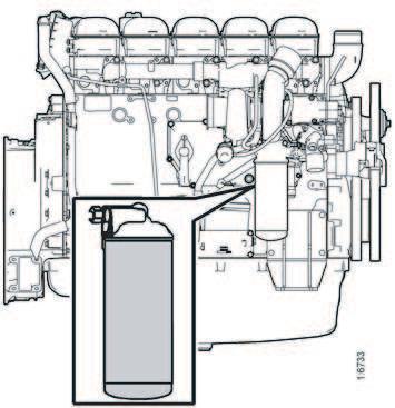
1.3. Replace oil fi lter 3* (at the same time as oil change, item 1.1) 1. The fi lter is located on the right hand side of the engine.
2. Remove the old fi lter and discard it according to environmental requirements. 3. Oil the rubber gasket on the new genuine fi lter.
4. Fit the new genuine fi lter. 5. Tighten the fi lter by hand as tight as possible. 6. Start the engine and check for leaks. If the deposits in the centrifugal cleaner exceed 20 mm, the oil fi lter must be changed more often, at the same time as cleaning the centrifugal fi lter and changing the oil.
NOTE
• Never use tools to tighten the fi lter. It can be damaged and thecirculation obstructed! • Use only genuine fi lter!
500 Hours Service Maintenance to be performed every 500 hours of operation.
1.4. External cleaning of the radiator, at least once a year 5*
If necessary, the cooling system should be cleaned more often. 1. Clean externally the radiator fi ns and hoses by using a brush. The radiator can also be washed with water from the backside. 2. Check that the radiator is not blocked on the air side and that the fi ns are not damaged. 3. Carefully scrape the deposit away from the radiator fi ns. If necessary, a paraffi n-based engine cleaner may be used. 4. Check the fi ns, rubber hoses, clamps and pipes for corrosion, damage and leakages. 5. Bent fi ns can be carefully straightened, e.g. using a steel wire brush.
CAUTION
The cooling system must not be cleaned using caustic soda. It can damage aluminium parts.
10 - 15 mm 500 Hours Service Maintenance to be performed every 500 hours of operation.
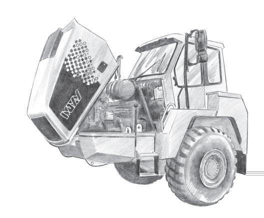
1.5. Check batteries 11* • Checking of batteries shall also be carried out after the fi rst 8 hours of operation. 1. Open left hand side fender cover (open the bonnet fi rst and then the fender cover) 2. Undo the plugs and check electrolyte level in all cells. 3. The fl uid level in each cell shall be between 10-15 mm above the plates. 4. Refi ll with distilled water if level is lower.
NOTE
Only distilled or chemically cleaned water must be used.
1.6. Check battery terminals for tightness and corrosion
Clean if necessary, apply acid-free vaseline on the terminals and retighten the clamps.
500 Hours Service Maintenance to be performed every 500 hours of operation.
2. Drive line
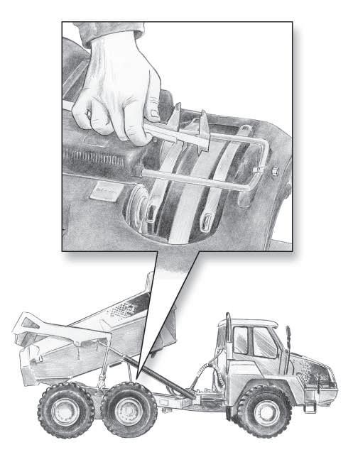
2.1. Check oil levels • Measurements must be carried out when dump truck is parked on a horizontal ground. • Check that oil level is near the bottom edge of the plugs. • Refi ll with oil if level is too low. • If the dump truck tandem housing is angled, the reading will be incorrect.
CAUTION
Be aware of possible internal pressure when the oil is hot!
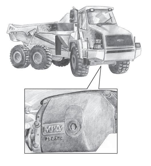
1. Front differential 30* Use a hexagonal key to unscrew the upper fi lling/ level plug. • Plug torque: 80 Nm
2. Rear differential 31* Use a hexagonal key to unscrew the fi lling/level plug at the rear of housing. • Plug torque: 80 Nm.
500 Hours Service Maintenance to be performed every 500 hours of operation.
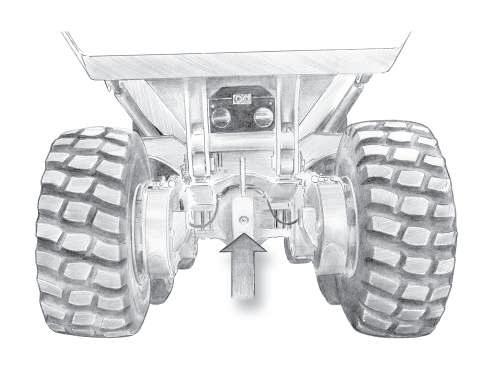
3. Tandem housings 32* Use a hexagonal key to unscrew the level plugs on the inside of the housing. • Plug torque: 80 Nm.
4. Front reduction gears 33* Turn the hubs until level indicator is horizontal. Use a hexagonal key to unscrew the plugs. • Plug torque: 80 Nm.
Service brake
Parking brake 500 Hours Service Maintenance to be performed every 500 hours of operation.
3. Brake system
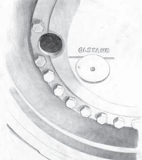
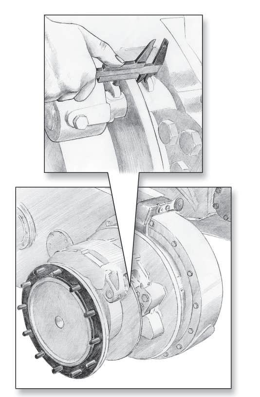
3.1. Check lining thickness • Ch e ck i n g o f b ra ke l i n i n g t h i ck n e s s s h a l l a ls o b e carried out after the fi rst 500 hours of operation. 1. Service brakes:
Check brake linings. Brake linings should be changed before the thickness of the linings on the most worn areas reaches 3,5 mm. • How often the brake linings have to be checked/ replaced depends on how much the brakes are used and/or applications. After checking the brake linings for the fi rst 500 hours, consider whether or not the brake linings should be checked more often, based on lining wear. 2. Parking brake:
Lift body and apply the body support.
Remove the protection on the top of the parking brake and check thickness of linings. Change when approaching limit. • In connection with replacement perform adjustment, see next page.
Standard lining thickness: Service brakes: 22.0 mm Parking brake: 20.0 mm Min. thickness: Service brakes: 3.5 mm. Parking brake: 5.1 mm.
CAUTION
This applies to normal driving. For rough operating conditions with much braking and/or driving in water, the brake linings should be checked more often!
1
Washer-adjuster plug Adjuster

Allen wrench 3.2. How to adjust the parking brake.
To be performed in connection with replacement of parking brake linings. • Before removing the parking brake linings, do as follows: 1. Apply the parking brake. 2. Lift the body. 3. Apply the body support (1) (see also safety instructions, chapter 2). 4. Stop the engine. 5. Secure the dump truck with wheel chocks (see also safety instructions, chapter 2) 6. Release the parking brake by the parking brake switch. 7. Remove the adjuster plug and washer from the cylinder bracket. 8. Use a 6 mm allen wrench to adjust the brake (turning the allen wrench in clockwise direction). Stop turning the allen wrench when you feel resistance, which indicates that the adjuster pistons are fully retracted. • When you de-adjust the brake (increase disc clearance) you will hear a "clicking" sound and feel a "pulsing" sensation during the adjustment. • To ensure that the automatic adjustment will occur: Adjust the brake an additional 1/4 turn after you reach the resistance point. • Do not use an air gun to adjust or de-adjust the parking brake! Components could be damaged. 9. The parking brake linings can now be replaced. • After installation of new parking brake linings, do as follows: 1. Adjust the caliper by reducing the caliper-to-disc clearance to ZERO (turning the allen wrench in counter clockwise direction).
2. Check that the load plate fully contacts the lining backing plate. 3. To increase the disc clearance, turn the allen wrench
SEVEN CLICKS in clockwise direction, which sets the initial clearance. 4. Install the adjuster plug and washer. • Tightening torque: 11-17 Nm 5. Apply and release the parking brake 15-20 times to allow the adjuster to set the fi nal caliper clearance.
500 Hours Service Maintenance to be performed every 500 hours of operation.
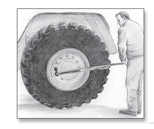
4. Wheels
4.1 Check wheel nuts torque. Torque setting 450 Nm.
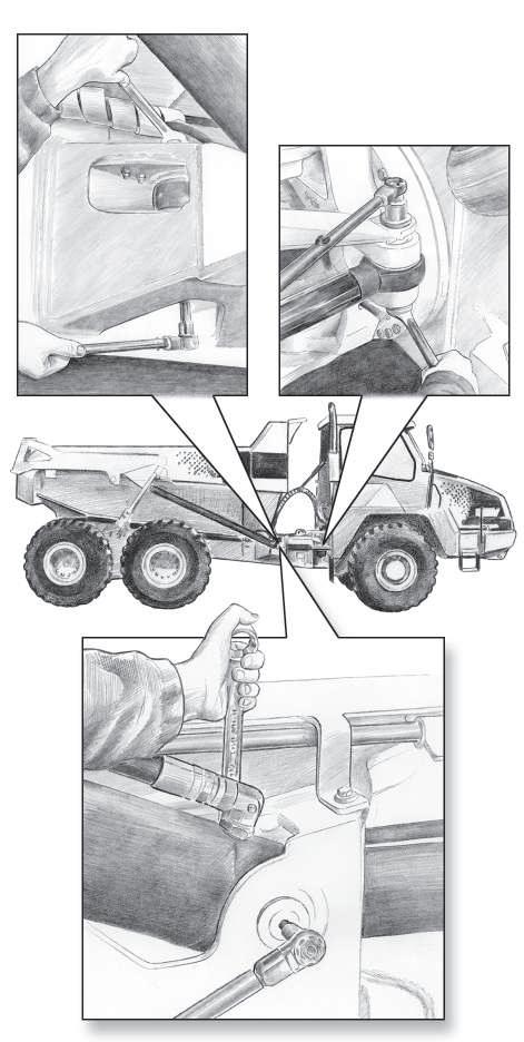
5. Tip- and steering cylinders
5.1 Check expander bolts. • Checking of the expander bolts torque setting shall also be carried out after the fi rst 100 hours of operation.
Torque setting: • Tip cylinder bolt: 250 Nm • Steering cylinder bolt: 380 Nm • The torque must be checked on on both sides of the bolts. • Be aware of the lubrication nipples on the bolts when checking the torque.
2
1
500 Hours Service Maintenance to be performed every 500 hours of operation.
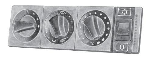
6. Cab ventilation
6.1. Air conditioner system, test operation 1. Start the engine. 2. Press down the air conditioner switch, set the fan switch to position 3 (see also chapter 3) and open all nozzles. 3. Check that the temperature in the cab decreases. • If the temperature does not decrease: • Check whether the fuse is burnt out, if yes, replace the fuse. • If the fuse is not burnt out, there can be a failure or too little refrigerant in the system: CONTACT YOUR LOCAL MOXY DEALER
WARNING
• If the air conditioning system does not work properly, contact your Moxy Dealer.
• Always use safety glasses or goggles, gloves, boiler suit and protective footwear when inspecting, servicing and repairing the air conditioning system.
• Refrigerant R134a has a property that can cause frostbite if it comes into contact with bare skin or eyes.
• Always work on the air conditioning system in well ventilated places.
• The system contains refrigerant R134a under pressure. Repair and refilling of the refrigerant circuit must only be done by accredited personnel.
• Dispose of waste oil/fl uids in an enviromentally friendly manner!
• High concentration of the refrigerant in gaseous form can cause drowsiness, headache, dizziness and at worst unconsciousness. Very high concentration of the gas can even cause cardiac insuffi ciency. Do not smoke when servicing the air conditioning system!
• Be careful with all hoses connected to the air conditioning system. There is always a certain over pressure in the system. Therefore, never undo hoses or the fi ller opening on the compressor except during repairs to the system.
• If there is any suspicion of leakage, the system must not be fi lled up - leave the leakage site and contact your Moxy Dealer for repairs.
• Get your Moxy Dealer to check the air conditioning system yearly and refi ll refrigerant, if necessary.
• See also chapter 2, Safety Instructions
1
500 Hours Service Maintenance to be performed every 500 hours of operation.
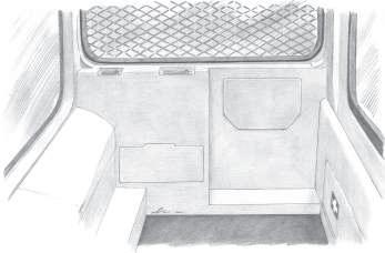
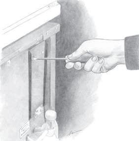
6.2. Check cab ventilation fi lter element condition 70* 1. Remove the rear panel on the right hand side inside the cab (behind the driver's seat). 2. Open the cover (1) with a screw driver. 3. There is two fi lter elements (2). 4. Check if the fi lter elements are clogged or damaged. • Replace if necessary. 5. Reassemble the opposite way. 6. Adjust the check interval if another requirement is experienced.
2

500 Hours Service Maintenance to be performed every 500 hours of operation.
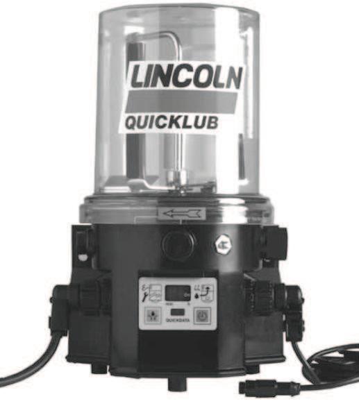
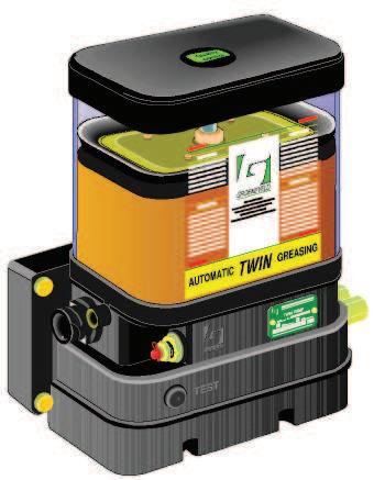
7.1. Check the system • Check the pump for damage and leakage. • Check the grease lines for damage and leakage. • Check, if possible, the condition of the grease points the system serves. Suffi cient fresh grease should be present. • Check the operation of the system. Perform a cycle test (see chapter 3 for how to perform a cycle test). Note that every time you perform a cycle test, grease is supplied to the grease points. • Clean the pump-unit and its surroundings.
NOTE
• If you use a high-pressure air or water gun to clean the dump truck, do not spray directly onto the pump unit. Water or dirt might enter the pump-unit through the de-aerating openings. • For cleaning the sytem use benzine or petroleum. Do not use tri-perchloroethylene or similar sol- vents. Also do not use polar organic solvents such as alcohol, methylacohol, acetone or similar.
500 Hours Service Maintenance to be performed every 500 hours of operation.
7.1. Check the system • Check the pump for damage and leakage. • Check the grease lines for damage and leakage. • Check, if possible, the condition of the grease points the system serves. Suffi cient fresh grease should be present. • Check the operation of the system. Perform a cycle test (see chapter 3 for how to perform a cycle test). Note that every time you perform a cycle test, grease is supplied to the grease points. • Clean the pump-unit and its surroundings.
NOTE
• If you use a high-pressure air or water gun to clean the dump truck, do not spray directly onto the pump unit. Water or dirt might enter the pump-unit through the de-aerating openings.
8. Continue with all items in 40 Hours Service.