
Maintenance Manual
ESR4500 Series Order Number: 812549-006 Pr inted in Ger many ● Status 2, Revision Level A
This master manual is subject to continual updates. It is meant exclusively for businesses authorized by CROWN. It is not permitted to pass on the contents or copies thereof to third parties.
CROWN Gabelstapler GmbH & Co. KG - European HeadquarterMoosacher Str. 52 80809 Munich Germany
Phone +49 (0)89 93 00 2 - 0
Fax +49 (0)89 93 00 2 - 133
All rights reserved under international and Pan-American Copyright Agreement. Copyright 2004 CROWN Equipment Corporation
TABLE OF CONTENT
I Printed in Germany
II Printed in Germany
Blank page
Table of Content
ESR4500 06/2004 • Printed in Germany MS-IDX-2140 III TABLE OF CONTENT
MA – SAFETYPAGESER-NO. CUT..................REV. Safety Symbols used in the Manual......................................3 General Maintenance and Repair Safety Notes...................3 Maintenance and Repair ................................................3 Before Leaving the Truck ................................................4 Before Carrying out Work on the Truck ..........................4 Before Operating the Truck .............................................4 Warnings and Labels on the Truck........................................4 ITD – INTRODUCTIONPAGESER-N0. CUTREV. General .....................................................................................7 Operating Instructions ....................................................7 Service Training ..............................................................7 Ordering Spare Parts ......................................................7 Using the Manual ............................................................7 M1 – LUBRICATION AND ADJUSTMENTPAGESER-N0. CUT..................REV. Lifting the Truck.......................................................................11 Towing the Truck.....................................................................11 Jacking up the Truck...............................................................12 Component Access ................................................................13 Access to the Motor Compartment ................................14 Removing the Floorboard ...............................................14 Plastic Panel Disassembly / Assembly ..........................14 Maintenance ............................................................................16 Recommended Lubricants and Oils ..............................16 Lubricants ...................................................................16 Cold Store Trucks........................................................16 Truck Decommissioning ..................................................16 Restoring the Truck to Service .......................................16 Battery Maintenance .......................................................16 Daily Safety Check..................................................................18 Inspection and Maintenance Schedule.................................20 Cold Store Trucks........................................................20 Torques....................................................................................26 M2 – HYDRAULICSPAGESER-N0. CUT..................REV. Hydraulic Symbols ..................................................................29 Functional Description ...........................................................33 Abbreviations ..................................................................33 Lifting...............................................................................35 Lowering..........................................................................35 Mast Reach Carriage Retraction ...................................37 Mast Reach Carriage Extension ....................................37 Tilt Back Circuit ...............................................................39 Tilt Down Circuit ..............................................................39 Sideshift Left ...................................................................41 Sideshift Right .................................................................41 Hydraulic Components ...........................................................42 Hydraulic Lines ...............................................................42 Valve Block ......................................................................43 Relief Valve RV1.........................................................43 Lowering Speed Adjustment Valve AVL......................44 Pressure Load Switch PLS .............................................44 Hydraulic Reservoir ........................................................45
TABLE OF CONTENT
Bleeding the 5th
ESR4500 06/2004 • Printed in Germany MS-IDX-2140 IV
M2 – HYDRAULICSPAGESER-N0. CUT..................REV. Discharging the Hydraulic Reser voir..........................45 Filling the Hydraulic Tank............................................45 Filter .................................................................................46 Replacing the Return Filter.........................................46 Replacing the Aeration Filter......................................47 Replacing the Suction Filter........................................47 Pump Motor .....................................................................48 Hydraulic Pump ...............................................................48 Disassembly ...............................................................48 Commissioning ...........................................................48
Hydraulic System.............................................50
Lift Cylinder .......................................50
.............................................50
.........................................51
......................................51
Bleeding the
Bleeding the Free
Bleeding the Lift Cylinders
Bleeding the Reach Cylinder
Bleeding the Sideshift Cylinder
.............................................51
Bleeding the Tilt Cylinders
Function Cylinder ................................51
....................................................51 Drift Tests .................................................................................52 Lift cylinder drift test .......................................................52 Tilt cylinder drift test .......................................................52 Causes of Drift ................................................................52 M3 – DRIVE UNITPAGE SER-N0. CUT..................REV. Gear unit ..................................................................................55 Preparation ..............................................................................55 Tools required: ............................................................55 Removal ..........................................................................55 Servicing .........................................................................55 General .......................................................................57 Gear Unit Disassembly / Assembly ...............................57 Disassembly ...............................................................57 Assembly ....................................................................57 ..................................................................................57 Preparing the gear unit.............................................57 Inserting the bevel pinion shaft .................................58 Assembling the flange shaft......................................58 Adjusting the Bevel Wheel Set..................................58 Checking the flank tooth bearing ..............................59 Final Assembly.........................................................59 Re-Assembly ...................................................................60 Traction motor .................................................................60 M4 – ELEKTRICSPAGESER-N0. CUT..................REV. Electrical Components ...........................................................63 SPS (Safety Switch)....................................................63 KYS (Key Switch)........................................................63 HNS (Horn Switch) .....................................................63 HN (Horn)...................................................................63 FS (Forward Switch)...................................................63 RS (Reverse Switch) ...................................................63 ACS (Accelerator Switch)...........................................63 BFS (Brake Fluid Switch) ............................................63 BLS (Battery Lock Switch) ..........................................63 ................................................................................................................... BS (Flashing Beacon Switch)63 FKS (Fork Tilt Switch) .................................................63 LS (Load Sensor) ........................................................63 POT1 (Traction potentiometer) ....................................63
Flushing the Cylinders
POT2 (Raise potentiometer) .......................................63
POT3 (Reach potentiometer) ......................................64
POT4 (Tilt potentiometer) ...........................................64
POT5 (Sideshift potentiometer) ..................................64
POT6 (5th hydraulic function potentiometer)..............64
PLS (Pressure load switch)........................................64
SES (Seat switch).......................................................64
SFS 1SA (Forward travel steering feedback sensor)..64
SFS 2 (Steering feedback sensor 2)...........................64
BRS (Parking brake switch)........................................64
BPS (Brake pressure switch)......................................64
ORS (Override switch)................................................64
ECR1 (Travel encoder)...............................................64
ECR2 (Lift encoder) ....................................................64
ECR3 (Steering feedback encoder)............................65
ECR4 (Steering encoder)...........................................65
ECR5 (Height encoder) ..............................................65
THS1 (Temperature sensor 1) ....................................65
THS2 (Temperature sensor 2) ....................................65
THS3 (Temperature switch 3) .....................................65
RES1 (Reach sensor 1)..............................................65
RES2 (Reach sensor 2)..............................................65
SVH (Lift valve)...........................................................65 PVL (Proportional valve lower)...................................65
PVRT (Proportional valve retract) ...............................66
PVRE (Proportional valve extend) ..............................66
PVAR (Proportional valve accessories r ight)..............66
PVAL (Proportional valve accessories left).................66 RV (Relief valve).........................................................66
MVL (Manual lowering valve)......................................66
AVL (Lowering speed adjustment valve)....................66
FU1 (TDM / Display control fuse) ...............................66
FU2 (VCM / HDM control fuse) ...................................66
FU3 (Brake control fuse).............................................66
FU4 (SDM power fuse)...............................................66
FU5 / FU6 (Options control fuses) .............................66
FU7 (Main fuse) ..........................................................66
FAN1 (Electric compar tment fan) ..............................66
FAN2 (traction and hydraulic module fan)...................66
FAN3, FAN4 (Motor compar tment fans).....................66
K1(R1-R10 Heating resistor relays)............................66
K2 (Heating fan relay).................................................67
K3 / K4 (Brake light relay) ...........................................67
K5 (Travel lights relay) ................................................67
K6 (Work lights relay).................................................67
K7 / K8 (Travel alarm relay)........................................67
K9 / K10 (Flashing beacon relay)...............................67
K12 / K13 (Options relay)...........................................67
SW (Work lights switch)..............................................67
SD (Travel lights switch) ..............................................67
SI (Indicator switch)....................................................67
ESR4500 Status Codes ...........................................................69 Status Codes ...................................................................69 When a Service Code Occurs ....................................69 Truck does not operate and there is no Status Code.69
1. Fault during power-up...........................................69
2. The fault is not electrical .......................................69
ESR4500 06/2004 • Printed in Germany MS-IDX-2140 V TABLE OF CONTENT
– ELEKTRICSPAGESER-N0. CUT..................REV.
M4
TABLE OF CONTENT
3. Malfunction in one of a group of unmonitored inputs ........................................................................69
Statuscode 100 - 102 .....................................................71 Statuscode 110 - 120 .....................................................72
Statuscode 121 - 130 .....................................................73
Statuscode 131 - 160 .....................................................74
Statuscode 325 - 330 .....................................................111 Statuscode 340 ...............................................................112 Statuscode 341 ...............................................................113
Statuscode 343 - 381 .....................................................114
Statuscode 382 - 383 .....................................................115
Statuscode 384 - 385 .....................................................116
Statuscode 430 - 431 .....................................................117
Statuscode 460 - 462 .....................................................118
Statuscode 463 - 465 .....................................................119
Statuscode 840 - 841 .....................................................120
Statuscode 880 ...............................................................121
Statuscode 881 ...............................................................122
Statuscode 883 ...............................................................123
Statuscode 884 ...............................................................124
Statuscode 885 ...............................................................125
Statuscode 886 ...............................................................126
ESR4500 06/2004 • Printed in Germany MS-IDX-2140 VI
CUT..................REV.
M4 – ELEKTRICSPAGESER-N0.
Statuscode
Statuscode
Statuscode
Statuscode 249
Statuscode
Statuscode
Statuscode
Statuscode
Statuscode
Statuscode
Statuscode
Statuscode
Statuscode
Statuscode
Statuscode 180 - 181 .....................................................75 Statuscode 182 - 183 .....................................................76 Statuscode 184 - 200 .....................................................77 Statuscode 201 - 210 .....................................................78 Statuscode 211 - 213 .....................................................79
214 - 220 .....................................................80 Statuscode 221 - 222 .....................................................81 Statuscode 223 - 224 .....................................................82 Statuscode 225 - 230 .....................................................83 Statuscode 240 ...............................................................84 Statuscode 241 ...............................................................85 Statuscode 243 ...............................................................86 Statuscode 244 ...............................................................87
246 ...............................................................88
247 ...............................................................89
...............................................................90
250 ...............................................................91
252 ...............................................................92
253 ...............................................................93
260 ...............................................................94
261 ...............................................................95 Statuscode 262 ...............................................................96
263 ...............................................................97
264 ...............................................................98
265 ...............................................................99
266 ...............................................................100 Statuscode 267 ...............................................................101 Statuscode 268 ...............................................................102 Statuscode 280 - 282 .....................................................103 Statuscode 283 - 284 .....................................................104
285 - 300 .....................................................105 Statuscode 301 - 310 .....................................................106 Statuscode 311 - 313 .....................................................107 Statuscode 314 - 320 .....................................................108 Statuscode 321 - 322 .....................................................109 Statuscode 323 - 324 .....................................................110
ESR4500 06/2004 • Printed in Germany MS-IDX-2140 VII TABLE OF CONTENT M4 – ELEKTRICSPAGESER-N0. CUT..................REV. APPENDIX ......................................................................127 Display not active........................................................127 Main contactor switches continuously ON/OFF ......................................................................127 Only battery discharge indicator and message display active...............................................127 Main contactor briefly activated after power up..........127 Service Level...........................................................................129 Display .............................................................................129 Design and Functions .................................................129 Steer Angle Display..................................................129 Travel Direction Display............................................129 Battery Charge Status Display.................................129 Operator error display...............................................129 Service Display.........................................................130 Function Keys ...........................................................130 Message Display ......................................................130 Capacity Data Monitor................................................130 Brake Fluid Level Indicator .......................................130 Steer Fault Display....................................................130 Parking Brake Display...............................................130 Performance Setting Display....................................130 Operator Menu ........................................................................131 Tilt Position - Assist On / Off.......................................132 Rack Height Select On / Off........................................133 Programming Rack Height Select ...............................133 Programming Rack Height Select ... ...........................134 Service Level...........................................................................135 Chapter structure : ..........................................................135 ANALYZER.................................................................135 A1 STATUS...............................................................135 A2 INPUTS.................................................................135 A3 OUTPUTS.............................................................135 CALIBRATION ............................................................135 C1 Accelerator Pedal................................................135 C2 Raise Lower Handle............................................135 C3 Reach Handle .....................................................135
Tilt Handle ...........................................................135
Sideshift Handle ..................................................136
5th Function Handle............................................136 C7 Height..................................................................136 C8 Weight.................................................................136 C9 Fork Positioning ...................................................136 C10 Reach retract slow down...................................136 C11 Save?................................................................136 FEATURE ....................................................................136 F1 Truck size.............................................................136 F2 FLS Switch ..........................................................136 F3 Height Encoder ....................................................136 F4 Lower Cut out ......................................................136 F5 Fifth Function .......................................................136
Max Load.............................................................136
Capacity Data Monitor CDM................................136
Alarm 2................................................................136
Beacon ................................................................137
User Performance..............................................137 F11 User Codes ........................................................137 F12 Language...........................................................137
C4
C5
C6
F6
F7
F8
F9
F10
TABLE OF CONTENT
ESR4500 06/2004 • Printed in Germany MS-IDX-2140 VIII
M4 – ELEKTRICSPAGESER-N0. CUT..................REV. F13 Truck lockout......................................................137 F14 Rack select ........................................................137 F15 Height & weight on/off .......................................137 F16 Timer on/off ........................................................137 F17 Error log on/off...................................................137 F18 Operator Alar m1 on/off ......................................137 F19 Battery low level alarm......................................137 F20 Fork positioning .................................................137 F21 Change value Euro/US......................................137 F22 Save...................................................................137 HOUR METER............................................................137 H1 Run......................................................................137 H2 TDM Traction Drive Module.................................137 H3 HDM Pump Drive Module...................................137 H4 VCM Vehicle Controll Module ..............................137 H5 SDM Steer Drive Module....................................137 H6 Display.................................................................137 H7 Set Service Timer................................................137 H8 Escape................................................................137 LOG EVENTS.............................................................137 L1 History ..................................................................137 L2 Totals ....................................................................137 L3 Erase...................................................................137 L4 Escape.................................................................137 PERFORMANCE ........................................................138 P1 Setup P1 ..............................................................138 P2 Setup P2 ..............................................................138 P3 Setup P3 ..............................................................138 P4 BDI setting ...........................................................138 P5 Travel > LCS........................................................138 P6 Travel > FLS.........................................................138 P7 Travel > Custom ...................................................138 P8 Lower > Custom..................................................138 P9 Reach > Custom.................................................138 P10 5th Function left.................................................138 P11 5th Function r ight..............................................138 P12 Steer low speed.................................................138 P13 Steer high speed...............................................138 P14 Brake at ramp....................................................138 P15 Save..................................................................138 UTILITIES...................................................................138 U1 Software Version.................................................138 U2 Hour Set..............................................................138 U3 Accy Override......................................................138 U4 Escape................................................................138 Overview of Performance Default Settings ..........................139 Service Menu...........................................................................140 Access to Service Level .................................................140 Overview of menu items .............................................140 Analyzer ....................................................................140 Calibration .................................................................140 Feature ......................................................................140 Hour Meter ................................................................140 Log Events ................................................................140 Performance.............................................................140 Utilities......................................................................140 Analyzer ...........................................................................142 A1.1 - A1.12 Status.....................................................142
A2.1 - A2.6 Inputs.......................................................143
A2.7 - A2.13 Inputs.....................................................144
A2.14 - A2.20 Inputs...................................................145
A2.21 - A2.25 Inputs..................................................146
A2.26 - A2.32 Inputs...................................................147
A2.33 - A2.37 Inputs...................................................148
A3.1 - A3.9 Outputs ....................................................149
A3.10 - A3.16 Outputs ................................................150
A3.17 - A3.18 Outputs ................................................151
C1 - C3 Calibration.....................................................152
C4 - C5 Calibration.....................................................153
C6 - C7.1 Calibration..................................................154
C7.1.3 Calibration .......................................................155
C7.2 Calibration
C7.3 Calibration
C7.3.4 - C7.5 Calibration............................................158
C8 Calibration.............................................................159
C9
P1 - P1.5.1
P1.6 - P1.10.1
P1.11 - P1.15
P2
ESR4500 06/2004 • Printed in Germany MS-IDX-2140 IX
OF CONTENT
ELEKTRICSPAGESER-N0. CUT..................REV.
TABLE
M4 –
Calibration .......................................................................152
..........................................................156
..........................................................157
Calibration.............................................................160
11.2 Calibration.................................................161 Feature ............................................................................162
- F3 Features.........................................................162
- F6 Features.........................................................163
Features......................................................164
Features .................................................................165
C10 -
F1
F4
F7 - F7.7
F8
F10 Features.......................................................166 F11 Features ...............................................................167
- F14 Features.....................................................168
F19 Features.....................................................169 F20
F22 Features.....................................................170
Hour meter .....................................................171 H4
Hour meter .....................................................172 Log Events......................................................................173
F9 -
F12
F15 -
-
H1 - H3
- H8
Features......................................................173
L1 - L3.2
Features...................................................174 Performance ....................................................................175
L3.2.1 - L4
Performance............................................175
Performance.......................................176
Performance........................................177
- P6 Performance..................................................178
Utilities .............................................................................181
Utilities...........................................................181
Utilities...........................................................182 Control Module Safety Test....................................................183 General ............................................................................183 Steer Module Safety Test ...............................................183 Preparatory measures................................................183 Procedure ...................................................................183 Drive Module Safety Test ................................................184 Tools required.............................................................184 Preparatory measures................................................184 Procedure ...................................................................184 Final procedure ...........................................................185
P7 - P10 Performance................................................179 P11 - P15.2 Performance...........................................180
U1 - U2
U3 - U4
TABLE OF CONTENT
M5 – BRAKEPAGE SER-N0. CUT..................REV.
Load
M6 – STEERINGPAGESER-N0. CUT..................REV.
Steering ....................................................................................197
Example 1: Manual wheel change, drive wheel turned 160° to the right..........................................................199 Ending the error routine............................................199
Example 2: Manual wheel change, drive wheel turned 70° to the right............................................................200
Setting the SFS … proximity switches ...........................202 Replacing the steer motor ..............................................202
M7 – MASTPAGE SER-N0. CUT..................REV. Mast ..........................................................................................211
ESR4500 06/2004 • Printed in Germany MS-IDX-2140 X
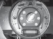
Wheel Brake...................................................................189 General ............................................................................189
Disassembly
Assembly
General
Disassembly
Brake......................................................................192 Disassembly
Test and Inspection.....................................................192 Assembly .........................................................................192 Air gap setting
Brake Lining ....................................................................189
...............................................................189
....................................................................189 Wheel Brake Cylinder .....................................................190
.......................................................................190
...............................................................190 Assembly ....................................................................190 Bleeding the load wheel brake and replacing the brake fluid...........................................................190 Operating
....................................................................192
.................................................................192 Setting the brake pedal clearance .................................194
General
Functional Description
Quadrant
Definition
Error routine
When
Ending
............................................................................197
................................................197
-
...................................................198
....................................................................198
the error routine star ts ….................................198
the error routine..............................................198 Causes of error routine activation ..................................198 Other error causes ..........................................................198 Examples of steer faults .................................................199
Disassembly
Disassembly ...............................................................202 Assembly ....................................................................202 Steering wheel ................................................................204
...............................................................204 Assembly ....................................................................204 Steering Sensor (ECR4) .................................................206 Disassembly ...............................................................206 Assembly ....................................................................206
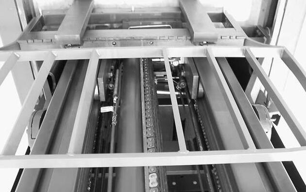
General ............................................................................211 Torque Requirements .................................................211 Lifting Gear Minimum Capacity...................................211 Mast Testing (Assembled) ..............................................212 Flaking ........................................................................212 Mast Shock Absorbers ................................................212 Mast end stops ...........................................................212 Fork Adjustment ..........................................................212 Mast Removal and Assembly.................................................213
ESR4500 06/2004 • Printed in Germany MS-IDX-2140 XI TABLE OF CONTENT M7 – MASTPAGE SER-N0. CUT..................REV. General ............................................................................213 Disassembly ....................................................................213 Assembly .........................................................................215 Dismantling and Assembling the Mast .................................216 General ............................................................................216 Dismantling .....................................................................216 Fork Carriage Removal...............................................216 2nd Mast Stage Removal...........................................216 1st Mast Stage Removal.............................................216 Replacing the Mast Rollers....................................................218 General ............................................................................218 Mast Roller Assembly .....................................................218 Calculating the Roller Diameter..................................218 Calculating the Required Number of Shims...............218 Outer Mast / 1st Mast Stage .....................................218 1st Mast Stage / 2nd Mast Stage .............................220 Fork Carriage............................................................222 Final Work and Settings .................................................223 Free lift cylinder removal / installation with mast attached224 General ............................................................................224 Torque Requirements .................................................224 Lifting Gear Minimum Capacity...................................224 Disassembly ....................................................................224 Assembly .........................................................................225 Lift cylinder removal / assembly ............................................228 General ............................................................................228 Lifting Gear Minimum Capacity...................................228 Disassembly ....................................................................228 Assembly .........................................................................230 Lift Chains...............................................................................232 General ............................................................................232 Inspection ........................................................................232 Cleaning ......................................................................232 Wear...........................................................................232 Freedom of Movement of Chain Links ........................233 Chain Tension.............................................................233 Chain Anchor and Pulleys..........................................234 Worn Connection Plates.............................................234 Protruding or Tur ned Chain Pins .................................234 Corrosion ....................................................................234 Chain Lateral Wear.....................................................235 Uneven Chain Tension..............................................235 Misalignment of Lift Components .............................235 Lift Chain Lubrication ......................................................236 Detaching Lift Chains .....................................................237 Tools and Equipment Required ......................................237 Detachment .....................................................................237 Fork Tines ................................................................................238 General ............................................................................238 Terms..........................................................................238 Fork Identification .......................................................238 Repairs ............................................................................238 Checking the Fork ...........................................................238 Crack Inspection .........................................................238 Verticality Test.............................................................239 Fork Blade Warping....................................................239 Measuring the Fork Tip Width ........................................239 Fork Tine Height Difference ...........................................239
TABLE OF CONTENT
ESR4500 06/2004 • Printed in Germany MS-IDX-2140 XII
– MASTPAGE SER-N0. CUT..................REV. Stop Mechanism .............................................................240 Fork Blade Wear .............................................................240 Reach .......................................................................................242 Disassembly ....................................................................242 Assembly .........................................................................242 Side Roller Adjustment ...............................................242 Backing Roller Adjustment ..........................................243 Reach Cylinder ........................................................................244 Disassembly ....................................................................244 Assembly .........................................................................244 Integrated Sideshifter.............................................................245 Disassembly ....................................................................245 Assembly .........................................................................245
– CYLINDERSPAGE SER-N0. CUT..................REV. Cylinders ..................................................................................249 General ............................................................................249 Safety when working on hydraulic systems................249 General Instructions for Repairing Hydraulic Components ...............................................................249 Rod Seal Assembly.................................................................250 General ............................................................................250 Large Rod Seal Assembly ..............................................250 Small Seal Rod Assembly ..............................................251 Rod Seal Assembly, Sealing Lip First ............................252 Lift cylinder..............................................................................255 General ............................................................................255 Removal and Assembly ..................................................255 Dismantling .....................................................................255 Rod Seal Removal......................................................255 Piston Rod Removal...................................................255 Assembly .........................................................................255 Piston Rod Assembly..................................................255 Installing the Rod Seal................................................255 Free-Lift Cylinder ....................................................................259 General ............................................................................259 Removal and Assembly ..................................................259 Dismantling .....................................................................259 Rod Seal Removal......................................................259 Piston Rod Removal...................................................259 Cushion Removal........................................................259 Assembly .........................................................................259 Cushion Installation ....................................................259 Piston Rod Assembly..................................................259 Installing the Rod Seal................................................259 Reach Cylinder ........................................................................263 General ............................................................................263 Removal and Assembly ..................................................263 Dismantling .....................................................................263 Rod Seal Removal......................................................263 Piston Rod Removal...................................................263 Assembly .........................................................................263 Piston Rod Assembly..................................................263 Installing the Rod Seal................................................263 Sideshift, Cylinder ...................................................................266 Dismantling .....................................................................266 Assembly .........................................................................266
M7
M8
Wiring Diagram - AC System .................................................273
Wiring Diagram Option...........................................................275
Wiring Diagram Coldstore
Harness:
Harness
Harness Coldstore..................................................................288
Harness Working Light12 V....................................................289
Harness Working Light 24 V...................................................290
Harness Driving Light.............................................................291
Harness Travel Alarm..............................................................292
Harness DC/DC Converter with Harness Options 813445................................................293
Harness DC/DC Converter without Harness Options 813445..........................................294
Harness Heated Seat ..............................................................295
Harness 12V / 24V Supply to B/W Screen .............................296
Harness Monitor B/W or Connection Box to Connector Panel.................................................................297
Harness (Camera) Connector Panel to Reach Carriage......298
Harness (Camera) Reach Carriage to Mast..........................299
Harness (Camera) Mast to Camera.......................................300
Harness (Camera) TFT Display to Connection Box.............301
Harness 12 V Supply to Connection Box ..............................302
Harness and Installation Drawing 6th Function ...................303
Harness Davis Derby System................................................304
Davis Derby EV 16 Circuit Program......................................305
Davis Derby S 16 Circuit Program.........................................306
Harness 1 Coldstore Cabin....................................................307
Harness 2 Coldstore Cabin....................................................308
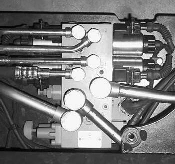
Hydraulic Schematic ...............................................................311
Hydraulic Lines to the Valve Block........................................312
ESR4500 06/2004 • Printed in Germany MS-IDX-2140 XIII TABLE OF CONTENT DIA – ELECTRICAL DIAGRAMSPAGESER-N0. CUT..................REV.
Wiring Diagram - AC System .................................................274
Cabin...........................................276
Harness
Main Harness ...........................................................................280 PARTS_TABLE..........................................................281 Connector Table......................................................................281 PARTS_TABLE..........................................................281 WIRE_TABLE ............................................................281 Connector Table......................................................................282 WIRE_TABLE ............................................................282 WIRE_TABLE
Main
...........................................................................279
............................................................282
Connector Panel to Reach Carriage.....................283
Harness: Reach Carriage .......................................................284 Harness Options .....................................................................285
Harness Beacon ......................................................................286
Beacon Switch.........................................................287
HYD – HYDRAULIC SCHEMATICSPAGESER-N0. CUT..................REV.
Blank page
ESR4500 06/2004 • Printed in Germany MS-IDX-2140 XIV TABLE OF CONTENT
1 Printed in Germany SAFETY
page
2 Printed in Germany
Blank
Safety Symbols used in the Manual
To help guide you through the manual and to highlight particular danger areas, we have used graphic illustrations:
DANGER
This symbol indicates life-threatening risks
● Failure to comply with this notice may result in fatal injuries to yourself or other people.
WARNING
This symbol indicates the risk of serious injury and/or serious material damage.
● Failure to comply with this notice may result in severe injuries to yourself or other people and/or serious material damage.
CAUTION
This symbol indicates the risk of minor injury and/or minor material damage.
● Failure to comply with this notice may result in minor injuries to yourself or other people and/or minor material damage.
INFORMATION
Contains additional information with supplementary notes and hints.
OPTION
These items relate to optional features not supplied with the standard version.
General Maintenance and Repair Safety Notes
DANGER
Read the safety notices in the truck Maintenance and Operator's Manuals.
● Failure to do so could result in severe or fatal injuries to maintenance personnel and/or other persons.
Motorised vehicles can be dangerous if maintenance and service are neglected. For this reason maintenance and inspections must be carried out at regular short intervals by trained personnel working to approved company guidelines.
DANGER
Follow all national/local safety regulations applicable for maintenance work, e.g. for work on higher levels.
● Failure to do so could result in severe or fatal injuries to maintenance personnel and/or other persons.
Maintenance and Repair
1.Maintenance work must only be carried out in accordance with the test and maintenance program contained in the present Maintenance Manual and any applicable service notices.
2.Only qualified and authorised personnel may carry out work on the truck.
3.Always keep fire extinguishers in good working condition. Do not approach fluid levels or leaks with a naked flame.
4.To clean, use a non flammable, non combustible cleaning solution which is groundwater-neutral. Only carry out cleaning with an oil separator. Protect the electrical system from dampness.
5.Keep the service area clean, dry and wellventilated.
6.Do not allow oil to penetrate the ground or enter the draining system. Used oil must be recycled. Oil filters and desiccants must be treated as special waste products. Relevant applicable regulations must be followed.
7.Neutralise and thoroughly rinse any spilled battery fluid immediately.
8.Keep the truck clean. This will facilitate the location of loose or faulty components.
3 SC3200 03/2004 • Printed in Germany MS-MA-0000 SAFETY
SAFETY
9.Make sure that capacity and data plates, warnings and labels are legible at all times.
10.Alterations or modifications by the owner or operator are not permitted without the express written authorisation from Crown.
11.Only use original Crown spare parts to ensure the reliability, safety and suitability of the Crown truck.
Before Leaving the Truck
● Stop the truck.
● Lower the fork carriage fully.
● Apply the parking brake.
● Turn off the truck and remove the key.
● Block all wheels when parking on an uneven surface.
Before Carrying out Work on the Truck
● Raise the truck to free the drive wheel. Press the emergency Stop button and disconnect the battery.
● Prevent the truck from rolling away.
● Before carrying out work on the hoist frame, the lift mast or on the fork carriage: Block these parts according to maintenance instructions in order to prevent them from dropping.
● Only carry out operational testing when there is sufficient room to manoeuvre, to avoid the risk of injury to yourself and others.
Before Operating the Truck
● Check the safety devices.
● Get into the driver's seat.
● Check the operation of the lifting device, travel direction switch, speed control, steering, warning devices and brakes.
Warnings and Labels on the Truck
During regular maintenance check that the warnings and labels on the truck are complete and legible.
● Clean any illegible labels.
● Replace any faulty or missing labels.
The order and meaning of the warnings and labels on the truck are described in section 10.9 of the parts manual.
4 SC3200 03/2004 • Printed in Germany MS-MA-0000
INTRODUCTION
5 Printed in Germany
page
6 Printed in Germany
Blank
General
The present manual is designed for Customer Service engineers who wish to familiarise themselves with the maintenance work required for the various truck components.
It also contains troubleshooting sections which can be used to identify and remedy truck faults.
INFORMATION
This book is not an operating manual. It is designed solely for specialist personnel who have been trained and authorised to carry out the work described in the manual.
This manual therefore contains fewer and less detailed warnings than the Operator’s Manual, as the latter is aimed at persons who have very little or no prior experience at all.
Operating Instructions
This manual contains no operating instructions. An operating instructions manual is supplied with the vehicle. Additional copies can be ordered as required.
With the help of this manual you and your personnel will be able to ensure the long service life, operational safety and error free functioning of your CROWN vehicle.
Service Training
CROWN offers the appropriate vehicle related training for service personnel. Details on this training can be obtained from CROWN on request.
Ordering Spare Parts
The maintenance manual does not cover spare parts. These are listed in a separate manual.
Spare parts can be ordered by quoting:
● The truck specification number
● The truck model number
● The truck serial number
This information can be found on the truck’s data plate. Only if this information is provided can the order be processed quickly, correctly and reliably.
Please refer to the Technical Specifications Sheet for the utilisable loads, technical data and dimensions for thisseries. Brochures can be obtained from your CROWN dealer or from the following address:
CROWN Gabelstapler GmbH & Co.KG
Moosacher Str. 52 80809 Munich GERMANY
Tel.: +49 (0)89 / 93 002 -0
Fax: +49 (0)89 / 93 002 -175 oder 133
Using the Manual
The manual is divided into sections. The following table shows how the manual is structured.
SC3200 03/2004 • Printed in Germany MS-ITD-2232 7 INTRODUCTION
Maintenance Sections Section Description DX It Conten of Table A My Safet TD In Introductio 1 Mt Adjustmen and Lubrication 2 Ms Hydraulic 3 Mt Uni Drive 4 Ml Electrica 5 Me Brak 6 Mg Steerin 7 Mm Mechanis Lifting / Mast 8 Mr
IA Ds Diagram Electrical YD Hc Schemati Hydraulic A01M-gb
Cylinde
Blank page
8 0Printed in Germany
LUBRIFICATION AND ADJUSTMENT
9 Printed in Germany
page
10 Printed in Germany
Blank
Lifting the Truck
CAUTION
Scalding hazard!
Spilled battery acid can cause injuries and damage the truck.
You must remove the battery before transporting the truck.
DANGER
Falling loads are hazardous!
Accidents can result from lifting gear with insufficient capacity and unsecured loads.
Always use lifting gear with sufficient capacity and prevent the load slings from sliding.
Calculate the minimum capacity requirement based on the weight of the truck. This information can be found on the truck data plate.
Attach the 4 straps to the hitch points as shown.
MO-2140-019
Towing the Truck
If the truck has been switched off and is idle, it can be towed over short distances without having to release the drive wheel brake. A brokendown truck can be removed from its operating aisle using a fork lift truck with a minimum 2500 kg capacity.
● Tilt the forks down and position them under the chassis as illustrated in the diagram.
● Raise the truck approximately 20 mm off the ground. The drive wheel should not be in contact with the ground. Otherwise the truck will be damaged!
● Slowly tow the truck in a forward direction only (black arrow).
Support points
11 ESR4500 06/2004 • PRINTED IN GERMANY MS-M1-2140
ADJUSTMENT
LUBRIFICATION AND
MO-2140-020
LUBRIFICATION AND ADJUSTMENT
Jacking up the Truck
DANGER
Risk of injuries!
A non-supported or insufficiently supported truck or truck part can suddenly drop and seriously injure you if you leave your hands or other body parts underneath it.
Always support the raised truck on square blocks or other appropriate material to relieve the jack.
● Fully lower the forks.
● Place wedges in front of both load wheels.
● Apply a jack with sufficient capacity as centrally as possible on the skirting rail and lift the truck.
● Slide hard wooden blocks underneath the left and right-hand sides and lower the truck onto them.
● Apply the jack underneath the load wheel arm and raise until the load wheel is max. 10 mm off the ground (risk of tipping!).
● Slide a hard wooden block underneath and lower the truck onto it.
● Raise the other load wheel arm and lower it onto a hard wooden block.
12 ESR4500 06/2004 • Printed in Germany MS-M1-2140
MO-2140-021
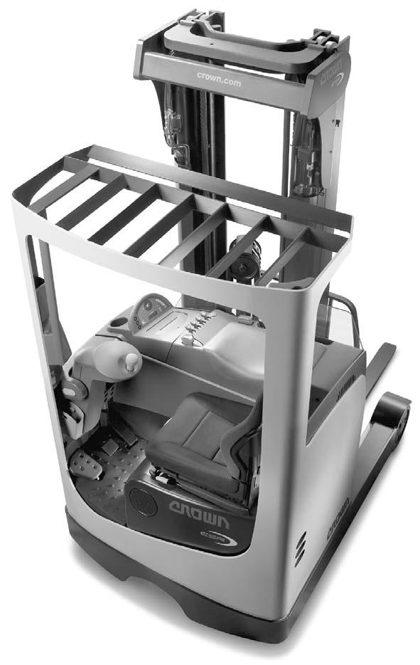
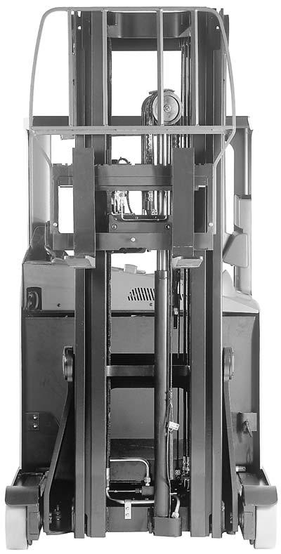
Component Access
In the course of regular maintenance the components inside the truck chassis can be reached by unscrewing the panels or simply by flipping up and lifting out the driver seat.
Detailled descriptions are contained on the next page.
DANGER
Danger of death!
When servicing or adjusting the drive motor, hydraulic system or truck drive module, accidentally starting the drive motor or a hydraulic function can fatally injure people standing in front, beside or behind the truck.
Lower the forks and retract the mast reach.
Jack up the truck so that the drive wheel is clear of the ground.
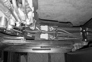
Underneath the panel
● VCM, TDM, HDM, SDM
● Line contactor
● Fuses
● Emergency Disconnect
● Fan
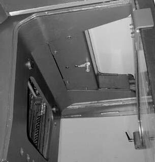
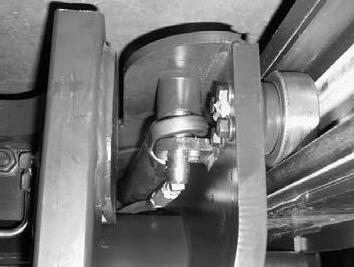
Underneath the steering column panel
● Steer sensor
Underneath the floorboard
● Main brake cylinder
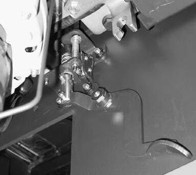
● Pedal mechanism of
● Accelerator pedal
● Brake pedal
● Safety pedal
● Horn
Underneath the driver’s seat
● Drive unit
● Brake
● Hydraulic motor, pump and reservoir
● Steer motor
● Connector panel
13 ESR4500 06/2004 • PRINTED IN GERMANY MS-M1-2140
ADJUSTMENT
LUBRIFICATION AND
MS-2140-013
Access to the Motor Compartment
● Push the seat forward.
● Open the quick release mechanism (see Fig. MO-2140-023).
● Push the seat backward.
● Flip the seat forward (Fig. MS-2140-015).
● Disconnect the cable to the seat switch on the connector panel (see double arrow Fig. MS2140-015)
● Lift out the seat from the top.
● Installation is the reverse of disassembly. Do not forget the cable to the seat switch!

Removing the Floorboard
Remove one screw (see Fig. MS-2140-014). Lift the floorboard backwards and up to remove it (seat must be removed first).
Plastic Panel Disassembly / Assembly
● Remove screw (1, see Fig. MS-2140-016).
● Raise the cover (2) and disconnect the electrical connections. Remove the cover (2).
● Remove screws (3).
● Remove panel (4).
● Installation is the reverse order.
14 ESR4500 06/2004 • Printed in Germany MS-M1-2140
AND ADJUSTMENT
LUBRIFICATION
MS-2140-015
MO-2140-023
MS-2140-014
3 3 4 3 2 1
MS-2140-016
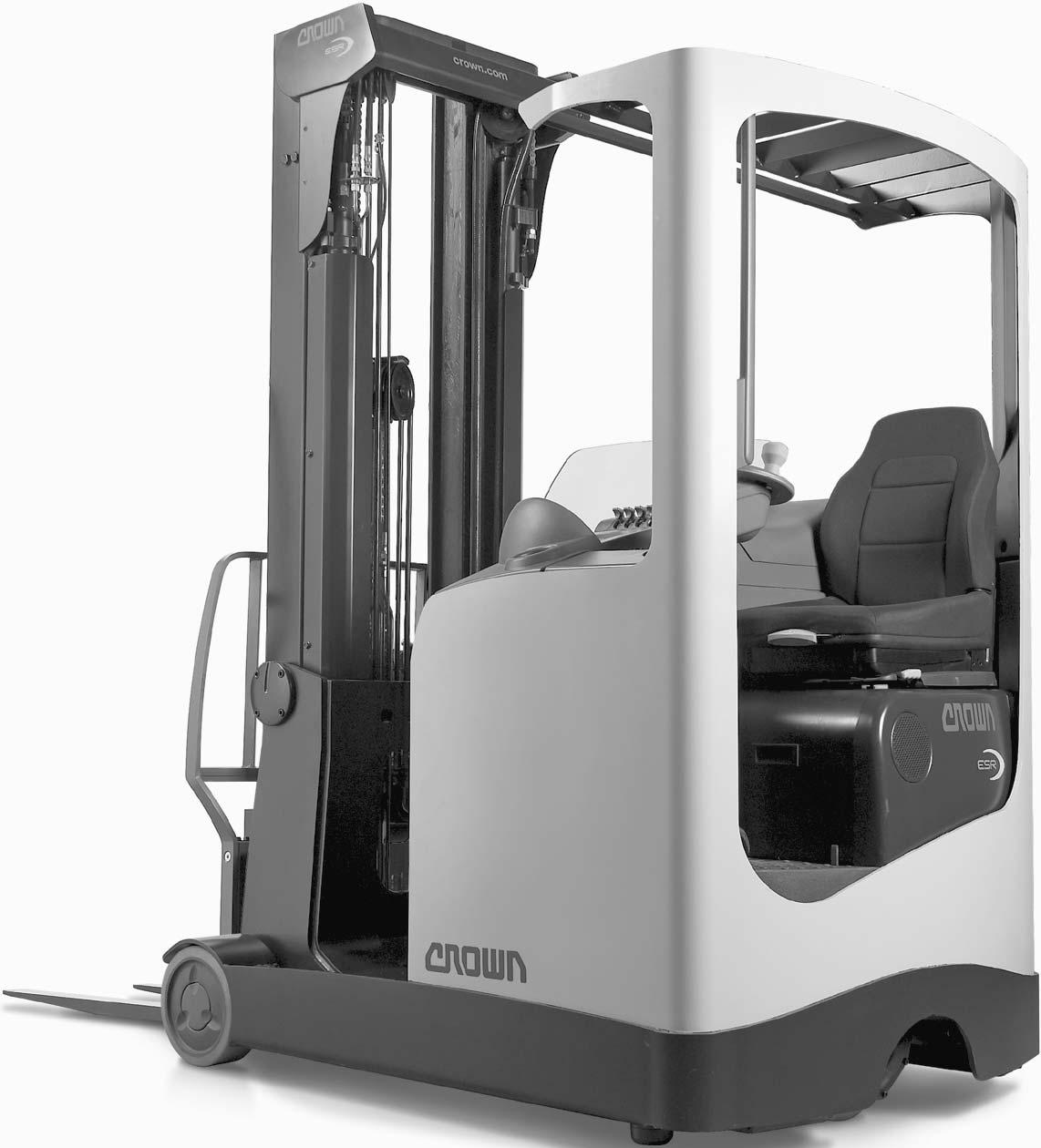
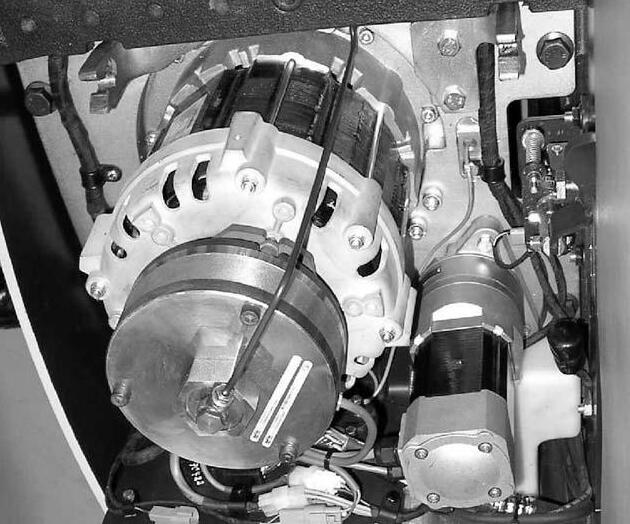
Vehicle Control Module VCM
Display
Optional Switches
Emergency Disconnect Switch
Steer Drive Module SDM Travel Direction Switch Main Contactor Main Fuse FU7
Traction Drive Module TDM Hydraulic Drive Module HDM Fuses Start Up Module
Steer Sensor
Safety Pedal
Brake Pedal
Brake Fluid Reservoir + Main Brake Cylinder
Drive Motor
Steer Motor
Connector panel
Pump Motor
Hydraulic Tank
15 ESR4500 06/2004 • PRINTED IN GERMANY MS-M1-2140
LUBRIFICATION AND ADJUSTMENT
MS-2140-017
Brake
LUBRIFICATION AND ADJUSTMENT
Maintenance
Recommended Lubricants and Oils
Lubricants
The following page lists typical lubricants which are also used by Crown in the factory. However, any lubricants with the same technical specifications can be used.
Cold Store Trucks
Special hydraulic oil, lubricant oils and grease for low temperature applications must be used for cold store trucks (see table on following page). All screws, washers, nuts, pins, retaining rings etc. must be treated regularly with an anti-corrosion solution CROWN no. 805236004. Electrical connections and components must be carefully protected against corrosion.
Maintenance intervals must be adapted to the conditions of use. They should be as frequent as possible to prevent excess wear. Please contact CROWN who will draw up an appropriate maintenance schedule for your conditions.
Truck Decommissioning
When taking the truck out of service for more than 3 months, proceed as follows:
● Disconnect the battery.
● Decommission the battery in accordance with the manufacturer's instructions.
● Clean the truck*. Grease the truck in accordance with the maintenance manual.
● If the truck is to be stored in hostile ambient conditions (e.g. saline atmosphere) treat the surfaces of the truck with a suitable solution to prevent corrosion.
● Do not park the truck in the open air or in a humid environment. The ideal location is a dry room with as constant a temperature and air humidity as possible. If the truck has to be covered, use material through which air can permeate rather than plastic sheets. Otherwise condensation water may form.
● Jack up the truck. Lower the chassis onto suitable wooden blocks in order to clear the wheels from the ground (this prevents the wheels from flattening under constant pressure).
● Every 3 months connect the battery, carry out a daily check and test the truck functions. Then disconnect the battery again.
Restoring the Truck to Service
When restoring the truck to service, proceed as follows:
● Remove any addition corrosion protection applied (except for cold store protection)*.
● Jack up the truck, remove the wooden blocks and lower the truck.
● Charge the battery or install a charged battery.
● Connect the battery.
● Carry out the daily check.
* Do not use high pressure cleaners and/or solvents on the truck. Do not use metal brushes. Do not wet-clean the electrical system and do not use flammable cleaning solutions.
Battery Maintenance
The condition of the battery will affect the performance and driving characteristics of the truck. Optimal maintenance (regular specific gravity and electrolyte level checks, keeping the cell tops clean) is key to maintaining the performance and useful life of the battery.
Service the battery in accordance with the battery manufacturer‘s instructions only.
16 ESR4500 06/2004 • Printed in Germany MS-M1-2140
LUBRIFICATION AND ADJUSTMENT
17 ESR4500 06/2004 • PRINTED IN GERMANY MS-M1-2140
Type Lubricant Description Product Manufacturer No. t Par CROWN Type
53002-001 0B temperature Low
SKL2
Aral Mobil 53002-005 0B B (chain) oil
40
40
Aral Esso Mobil 53002-007 0G temperature Low oil lubrication
Sl obi M8 53002-00 0G G oil
32
24
Aral
53001-003 0D temperature Low oil hydraulic 13
Aero Esso Mobil 53001-008 0D D oil
EPX-80W-90
Castrol
Shell 53002-002 0A temperature Low oil
SHC-LS75W-90
obi M6 53002-00 0A A fluid rake B4 DOT 53059-001 0J vinyl and Rubber dressing H grease pecial SS MO 2 ithium Lg nin Cor ow D2 63002-02 0M oil lubrication niversal U0 SEA4 C agent nti-corrosion Al Tecty cold for agent Corrosion trucks store 05236-004 8L01-gb
pose) pur (multi Grease HLP-2 Aralube LM-Grease A2 Regulus EP2 Beacon EP2 E2 Mobiluxe LX Retinax LGWM1 Aral Castrol y Centur Esso Maxol Mobil Shell SKF
grease
Aralube EP Lotemp Unirex
Lubrication
Kowal
+ HDX Essolube 1240 Delvac
626 HC
Hydraulic
GF Vitam AWS-32 Hyspin H32 Nuto
DTE 32 Tellus B110
Castrol Esso Mobil Shell GmbH Mineralölwerke Fuchs
J Univis HFA
Transmission
Castrol 80W-90 HD Spirax
mah Bur
transmission
obilube Ml
Safety Check rsuoh service 8 every ro aily D
Item tennompo C nctio A
Above the Battery
MS-2140-020
1 eat S damage for Check position fixed a in is seat the that sure Make
2 umn ol C ng teeri S xed. fi s i on ti posi umn's col ng steeri the that sure Make
3s anel P / overs C secure? and undamaged present, s panel / covers l l A
4 d el hi S afety S d? el shi through ty i l bi si vi Good damage for heck C secured y properl s i t i f i heck C
5 s ecal D s, Label 2- page , manual operator (see e bl egi l and ean cl present, l al are they that heck C 10)
6 age arri C Fork Forks, wear excess and fissures deformation, for Check a n i are nes ti fork the sure Make . ot. sl age carri the n i ocated l n pi atch l the th i w on, ti posi xed fi
7 cces- A ackrest, B Load e) cabl i appl f (i es sori damage for Check secured properly if Check
8 Chain Chain, Lift Anchor damage of gns si any and on deformati ssures, fi on, corrosi for heck C
9 s Wheel found es bodi gn forei any emove R es bodi gn forei any for and ear w for tyres heck C
10 truck? the under ground the on eakage l of gns si ny A t ni U Gear - ) l oi n (brow s heel w ve dri the byystem S c i ydraul H - ) l oi ght i (l mast and s chassi the ow bel area re enti the over
ystem S ng raki B - ggers outri the ow bel , heel w ve dri and pedal brake the een betw s chassi the ow bel d) ui fl ght i (l
18 ESR4500 06/2004 • Printed in Germany MS-M1-2140 LUBRIFICATION AND ADJUSTMENT 3
7
11 11 8, 21
8
4
MS-2140-018 MS-2140-019
8, 21
Daily
L02-gb
DANGER
Risk of accidents!
If you carry out the test run (test items 12 to 26) in your normal working environment, you risk endangering yourself and your colleagues, as you will have to concentrate on the truck.
(contd.) hours service 8 every or Daily
Component Action
11 y Batter
Carry out the test drive in an open area free of obstacles.
damage. any for Check secured. is cable y batter the that Checkleakage acid y batter for tment compar y batter Checktight. are y batter the of sides both on clamps the that Checkmanual maintenance y batter with accordance in y batter Check/maintain -
12 Switch Key switch key n ur TNOe th in indicators the of operation the check and dot) (green 3-3) page manual, operator see ( panel display
13 Brake Parking applied is brake parking the when inhibited be should Travel operation Check
14 Disconnect Emergency Switch, Seat Switch, Pedal Safety your take switch; disconnect emergency the Press (separately): operation Test moving are forks the while pedal safety the release seat; the off weight
15 n Hor operation Check
16 Steering play of absence and operation Check
17 Functions Travel
truck The speed full at then and first at slowly directions, both in truck the Move fixed a in remain should switch direction travel The jerky be not should movement position
18 Braking directions: both in braking Check settings on depending braking pedal: accelerator releasesettings on depending braking direction: travel changecheck? previous during than longer distance brake pedal: brake apply -
19 Fans ( flow air / operation Check ➔ hydraulic the when operate fans The illustration) see °C 35 of temperature operating an exceeds unit control
20 Latch y Batter mast the extend you when move not must y batter The
21 Functions Hydraulic additional sideshift, tilt, fork reach, mast (lifting/lowering, functions all Check function) speed: maximum with forks the lower and Raise ➔ automatically must forks The positions limit the approaching when down slow speed: maximum with carriage reach mast the retract and Extend ➔ mast The positions. limit reach the approaching when down slow automatically must play excessive for levers control the Check and lifting fork during pulleys and hoses chains, mast, of movement the Check lowering
22 Indicator Height fitted: if Reduction Speed + height lift corresponding as reduced is fork and mast truck, of speed the that Check exceeded. is
23 fitted: if Override + Cutout Lift of function Check height programmed the at stops automatically fork that Check switch override cutout lift/lower
24 + Cutout Lower fitted: if Override function Check outriggers the of height the at stops automatically fork that Check switch override cutout lift/lower of
25 fitted: if Assist Position Tilt horizontal in stops automatically fork that Check upward. and downward fork Tilt position.
26 Lights fitted: if operation. Check L03-gb
19 ESR4500 06/2004 • PRINTED IN GERMANY MS-M1-2140
LUBRIFICATION AND ADJUSTMENT
Pos.
LUBRIFICATION AND ADJUSTMENT
Inspection and Maintenance Schedule
The standard service intervals are based on single shift operation under normal conditions.
They should be reduced accordingly if the truck is to be operated in dusty or extreme conditions. Exact details should be discussed with a Crown service engineer.
Clean the respective components prior to inspection or maintenance: apply compressed air to them.
When carrying out maintenance routinely check for wear, corrosion, damage, component operation and safety. If in doubt, always replace a questionable part.
The inspection/maintenance work for longer service intervals must also include the items covered under the shorter intervals.
Cold Store Trucks
CAUTION
Before performing any maintenance work, the truck must be allowed to thaw out for at least 2 hours.
This will ensure all truck parts are equally warmed up.
Do not open any covers before the warming up phase is complete.This will avoid brittle fracturing of cables etc.
20 ESR4500 06/2004 • Printed in Germany MS-M1-2140
Blank page
ESR4500 06/2004 • Printed in Germany MS-M1-2140 21 LUBRICATION AND ADJUSTMENT


ESR4500 06/2004 • Printed in Germany MS-M1-2140 22
AND ADJUSTMENT I-22 L-6 I-17 I-14 I-14 L-3 I-5 L-1 I-6 I-15 I-19 I-10 I-16 L-5 I-13 I-13 L-5 I-7 L-5 L-8 I-9 I-16 MS-2140-075 MS-2140-074 MS-2140-081 MS-2140-077 MS-2140-071 MS-2140-079 MS-2140-073 MS-2140-078 I-20 I-18 I-37 L-9 I-24 I-29 I-29 I-28 I-26 MS-2140-080 MS-2140-064 MS-2140-017 L-11 I-33 L-12 I-37 MS-2140-024 I-32 I-38 I-35 I-24 I-30 I-31 MS-2140-063 I-49 I-46 I-50 I-46 I-46 I-46 I-47 I-47 I-48 I-51 I-52 I-52 MS-2140-085 MO-2140-004 I-3 I-4 L-2 I-1 I-2 I-4 L-4 I-11 I-12 I-21 L-7 I-21 I-23 I-50 MS-2140-084 L-13 I-29 I-25 I-27 L-10 I-36 I-36 I-34 I-34 I-34 I-40 I-39 I-41 I-42 I-44 I-45 I-43 I-53 I-53 I-54 I-53 I-54 I-55 I-52 L-14 L-14 MS-2140-086 I-58 I-57 I-59 I-60 I-61 L-16 I-69 I-68 I-64 I-64 I-64 I-63 I-39 L-15 I-58 I-66 I-62 L-17 L-18 L-15 I-65 I-66
LUBRICATION
LUBRIFICATION AND ADJUSTMENT
Maintenance and Inspection
= ... M, A, / Lubricate = L Inspection, = I
Action
-1 I. damage for guard overhead the Check
-2 Ie damag for structure chassis Check
-3 It attachmen and wear for skids Check
-4 Ie leakag and noise for transmission Check
-5 Ie secur are plate drive the on bolts mounting the sure Make CX
-1 LAy necessar if replenish oil, transmission Check CX
-2 LAl oi transmission Change
-6 Ir wea for wheel drive Check
-7 It attachmen wheel drive Check truck) new a for hours 100 - 50 after (+ CX
-9 It attachmen transmission Check CX
-10 It attachmen motor steer Check
-3 LMg toothin steering Grease
-4 LBt movemen of freedom for check and lubricate rails, seat Clean
I-11 reduction speed final and initial operation, mechanism reach Test
-12 Ie damag for carriage reach Check
-5 LBs roller lubricate and Check
-13 Iy necessar if adjust rollers, t suppor Check
-14 Is roller t suppor lateral adjust and Check
-15 It mas on attachment cylinder reach Check
I-16 present? relief strain secure, are connectors cable mast Check
-17 Iy necessar if replace wear, for buffer rubber Check
-18 I? secure and present cover block Hydraulic CX
I-19 secure are they sure make wear, and damage for rails slide Check
-20 Is minal ter container y batter of condition and operation Check
-21 In conditio locked in seat container y batter Check
-22 Iy necessar if adjust clearance, lateral piece slide Check
-6 LBe surfac contact outrigger the Check
-7 LB grease apply and operation test wear, for (optional) rollers y batter Check
-8 LBm mechanis locking y batter Grease
-23 In operatio lock y batter Test CX
23 ESR4500 06/2004 • PRINTED IN GERMANY MS-M1-2140
Store) Cold = C Standard, = (X Schedule
Hours Service / Years Item
1/4 500 1/2 1000 1 2000 2.5 5000
Lubricant
C
X
/
C / X
C / X
CX
CX
C / X
C / X
CX
C / X
C / X
C / X
C / X
C / X
C / X
C / X
C
X
C / X
/
CX
C / X
CX
CX
CX
CX
CX
L04-gb
LUBRIFICATION AND ADJUSTMENT
Maintenance and Inspection Lubricant = M, A, / Lubricate = L Inspection, = I
Action
-9 LJy necessar if replenish fluid, brake Check
-10 LJd flui brake Replace
I-24 (apply linings brake clean brakes, wheel load on wear lining brake Check y necessar if replace air), compressed y dr
-25 Ir wea of irrespective linings brake Replace
I-26 linings brake Clean brake; motor the on wear lining brake and gap air Check y necessar if replace air), compressed y dr (apply
-27 Ir wea of irrespective lining brake Replace
I-28 y necessar if adjust cylinder, brake main on clearance snifting Check C / X
-29 Ie damag and leaks for ts por and connections brake Check C / X
-11 LB pedal) safety + accelerator + pedal (brake mechanism pedal the Grease
-30 Ir wea / damage for wheels load the Check
-31 Ir wea and clearance for ts suppor wheel load the Check CX
-12 LD D/D y necessar as replenish and mast) the lower (fully oil hydraulic Check
-32 Is leak for frame reach in block hydraulic Check
-33 Is leak for carriage fork in block hydraulic aux Check
/ X
-34 Ie damag and leaks for connections and lines hoses, all Check C / X
I-35 are they sure make and wear for carriage reach in attachments hose Check secure C / X
-36 Ie damag and leaks for check secure, are cylinders all Check C / X
-13 LD /D D) litres 30 (requires oil hydraulic Replace
X I-37 filter aeration and filter n retur Replace new a for hours 100 - 50 after (+ truck)
-38 Ie valv lowering emergency Check
-39 Is display all of operation Test
-40 I. switch DISCONNECT EMERGENCY Test
-41 I. operation pedal safety Test
-42 I. operation n hor Test
-43 In operatio brake parking and switch brake parking Test
I-44 engage should switch the operation, switch direction travel Test C / X
-45 I. operation switch seat Test
C 1 or h 1000 y ever = annually X 2 =r o h 2000 y ever years two every
24 ESR4500 06/2004 • Printed in Germany MS-M1-2140
Store) Cold = C Standard, = (X
Hours Service / Years
1/4 500 1/2 1000 1 2000 5 2 5000
Schedule
Item
C / X
C2 X
C / X
CX
C / X
C
/ X
CX
C
X
/
C
X
/
C / X
C
CX
1 C2
C
X
/
C
X
/
C
X
/
C
/ X
C
/ X
C / X
C / X
L05-GB
LUBRIFICATION AND ADJUSTMENT
Maintenance and Inspection
= M, A, / Lubricate = L Inspection, = I
Action
-46 I. fixed are controllers the Check
I-47 EMERGENCY modules, drive lift and traction to connections line sure Make secure are FU7 fuse main and switch DISCONNECT
-48 Ie secur are connections potentiometer sure Make
-49 Ie secur are panel connector the on plugs sure Make
I-50 35°C) exceed must temperature operating module (drive operation fan Test
-51 Iy necessar as ts par n wor replace contactor, Check
I-52 secure are motors lift and drive from connections line all sure Make
-53 Ie damag for motors lift and drive from cables power Check
-54 Is attachment motor lift and drive Check
-14 LMg toothin shaft motor grease and Check
-55 Ir moto hydraulic on buffer rubber Check
-56 Is connection gauge temperature and sensor Check
-57 Ie damag for connectors and cables y batter Check
-58 Is minal ter y batter Check
-59 In conditio y batter Check
-60 Il leve acid and density acid Check
-61 It attachmen mast Check
-15 LGs anchor chain and chains lift lubricate and adjust Check,
I-62 position and damage for jacks tension and cables mast Check
-63 Is roller ter diver Check
-16 LBe greas apply and wear for sections mast Check
-64 Is stop and rollers mast Check
-65 Ie cabl sensor height and sensor height Check
I-66 reduction speed lift for switch mast or switch reset height Check
-67 Ie damag for carriage fork Check
-68 Ir wea and damage for forks Check
-17 LB test and grease clean, wear, for blocks slide and rollers check Sideshift: operation CX
-18 LB /B Be nippl grease via rail slide carriage fork the Lubricate CX
-69 Ie damag for check secure, is backrest load if Check
25 ESR4500 06/2004 • PRINTED IN GERMANY MS-M1-2140
Store) Cold
C Standard,
Hours Service / Years Item
1/4 500 1/2 1000 1 2000 5 2 5000
=
= (X Schedule
Lubricant
C / X
C / X
C / X
C / X
C / X
C / X
/
C
X
C / X
C / X
C / X
C / X
C / X
CX
CX
CX
CX
C / X
C / X
C
X
C
X
C / X
/
/
C / X
C / X
C / X
C / X
C
X
/
C / X C 1
1000 y ever = annually X = 2 t or h 2000 y ever wice L06-gb
or h
LUBRIFICATION AND ADJUSTMENT
Torques
The screw and nut strengths shown below are used in the manufacture of Crown trucks. The information on this page is designed to help determine the correct torque.
NOTE
The torques listed in the maintenance section always supersede those shown here. Screw Grade Marking Nut
Nuts and Srews Standard
Nuts and Screws Umbrako
26 ESR4500 06/2004 • Printed in Germany MS-M1-2140
8.8 8.8 8 12.9 12.9
Grade Marking
Grade 8.8 and 8 10.9 and 10 12.9 and 12 Size hread T) (Nm Torque 0,8 x 5 M65870 1 - 8 1 x 6 M0 184 1 - 2 16 1 - 14 1,25 x 8 M5 2 - 0 25 3 - 0 30 4 - 34 1,5 x 10 M5 4 - 0 45 6 - 0 65 7 - 70 1,75 x 12 M0 8 - 0 70 11 - 00 10 13 - 115 2 x 16 M0 19 - 70 10 27 - 40 20 32 - 280 2,5 x 20 M0 38 - 40 30 50 - 50 40 60 - 550 3 x 24 M0 65 - 80 50 90 - 00 80 105 - 900 3,5 x 30 M0 130 - 150 10 180 - 600 10 210 - 1850 T02-gb
Grade 10.8 and 10 12.9 and 12 Size hread T) (Nm Torque 0,8 x 5 M81 1 1 x 6 M419 1 1,25 x 8 M335 4 1,5 x 10 M366 8 1,75 x 12 M1 1 12 15 2 x 16 M0 7 22 37 2,5 x 20 M1 2 57 71 T03-gb
Grade
5 1 m0340 raphics: gb T01-g
Screw Marking
Nut Marking Grade
HYDRAULICS
27 Printed in Germany
page
28 Printed in Germany
Blank
Hydraulic Symbols
Vented reservoir with lines above the fluid level
Electric motor with unidirectional turn and speed
Vented reservoir with lines below the fluid level
Electric motor with unidirectional turn and variable speed
Filter or strainer
Hydraulic line with full flow (tubing or hose)
Pilot or drain line or drainage with limited flow
Lines not connected
Hydraulic pump with fixed displacement and single direction of turn
Hydraulic motor, bi-directional
Pressure gauge
Lines connected
Thermometer
Plugged port (test port)
Accumulator gas charged diaphragm type
Flow meter
ESR4500 06/2004 • Printed in Germany MS-2.0-0000 29 HYDRAULICS M M
M3559a
M3559
Pressure switch
Double-acting cylinder;unequal area
Manual actuator Spring, (bias to normal deenergised position)
Double-acting cylinder;equal area
Solenoid single coil or winding
Single-acting cylinderwith spring returned (rod end vented)
Hydraulic pilot operated
Single-acting cylinder ram type
Solenoid valve, pilot operated
Single-acting cylinder, with cushion
Dual solenoid
Assembly housing, manifold block
Proportional solenoid
Manual lever actuator
Pilot check valve (pilot to open)
30 ESR4500 06/2004 • Printed in Germany MS-2.0-0000 HYDRAULICS
M3560
Throttle, fixed
Throttle, adjustable
Pressure-compensated flow control, fixed
Shuttle valve
Single counterbalance valve assembly in manifold
Pressure-compensated flow control with reverse flow bypass; fixed.
Flow divider/combiner
Velocity fuse
Relief valve, fixed setting
Bypass flow control with controlled flow, pressure-regulated
Shut-off valve, manual
Torque generator
Relief valve, adjustable
Hydraulic steer unit
Check valve
ESR4500 06/2004 • Printed in Germany MS-2.0-0000 31 HYDRAULICS
T L R P T
P
M3561
2/2 way valve (two way, two switch positions)
Valve block with 3 operating units
3/2 way valve (three way, two switch positions)
4/2 way valve (four way, two switch positions)
4/3 way valve (four way, three switch positions)
4/3 way valve (four way, three switch positions); spring centered, manual activation
3/2 way valve (three way, two switch positions); spring bias solenoid control
32 ESR4500 06/2004 • Printed in Germany MS-2.0-0000 HYDRAULICS M3562
Functional Description
The hydraulic system consists essentially of three parts:
● Tank and pump
● Valve block
● Cylinders
The various hydraulic functions are generally controlled in the valve block.
Abbreviations
Hydraulic function potentiometers
The potentiometers are connected to their respective control levers and transmit an analog, proportional control signal to the truck control module.
DCVHDirectional Control Valve Hoist
DCVH is located inside the valve block. Depending on the command, it releases the path for the hydraulic oil - from the pump to the lift cylinders (raise) - from the lift cylinders back to the tank (lower)
SVHSolenoid Valve Hoist
SVH is a black and white valve and opens when lifting is selected. The lift speed is governed by the pump speed.
SVTSolenoid Valve Tilt
SVSSolenoid Valve Sideshift
SV5Solenoid Valve 5th function
AVLAdjustment Valve Lowering Speed
The AVL allows you to set the maximum lowering speed when PVL is fully opened (see “Valve Block” section).
MVLManual Valve Lower
In an emergency, MVL can be used to manually lower the fork carriage.
Attention: Close the valve again after lowering the fork carriage (turn anti-clockwise).
RV1Relief Valve
RV is used to restrict the maximum operating pressure and is set to 210 bar. RV must be reset when replaced.
PVLProportional Valve Lower
PVRTProportional Valve Retract*
PVREProportional Valve Reach*
PVALProportional Valve Accessories Left*
PVAL governs the upward tilt speed of the forks when TILT is selected, and the sideshift left speed when SIDESHIFT is selected.
PVAR Proportional Valve Accessories Right*
PVAR governs the downward tilt speed of the forks when TILT is selected, and the sideshift right speed when SIDESHIFT is selected.
PCLPressure Compensation Lowering
PCRPressure Compensation Reach
PCAPressure Compensation Accessories
For fork tilt, sideshift and optional 5th function
CVCheck Valve
CBVCounterbalanced Valve
PLSPressure Load Switch
When a load in excess of 400 kg is being lowered, PLS prevents the fork carriage from stopping abruptly. This prevents the mast from swaying. PLS must be reset when replaced (to 400 kg).
*If PVRT, PVRE, PVAL or PVAR fail, the complete valve block must be replaced. The magnetic coils can be individually replaced.
33 ESR4500 06/2004 • PRINTED IN GERMANY MS-MA-2140 HYDRAULICS
POT2 to POT6
Lifting
Suction Pilot Pressure Return
Lowering Pressure
34 ESR4500 06/2004 • Printed in Germany MS-M2.0-2140
HYDRAULICS
MS-2140-027
MS-2140-028
Lifting
“Lifting” is requested by pulling the raise/lower control lever. This changes the voltage on the loop of the raise potentiometer POT2. As a result, the main control module VCM switches on the pump and the magnet of the SVH raise pilot valve.
The SVH valve drives the DCVH raise/lower spool. The spool opens.
The lift speed is controlled by the pump motor speed in proportion to the movement of the control lever.
The oil flows from input P of the valve block through the DCVH spool via output A to the hydraulic cylinders. The hydraulic cylinders extend.
During raising, the “lower” control pressure side of the DCVH spool is connected to the tank return line via the lowering valve PVL. This is necessary to prevent any
Lowering
“Lowering” is requested by pushing the raise/lower control lever forward. This changes the voltage on the loop of the raise potentiometer POT2. As a result, the main control module VCM switches on the magnet of the lowering proportional valve PVL.
The PVL valve drives the DCVH raise/lower spool. The spool opens.
The oil then flows from the hydraulic cylinders, via port A of the valve block through the flow control valve PCL and the spool to output T, and from there via the return line back to the tank. The hydraulic cylinders retract.
In proportion to the movement of the control lever, the lowering proportional valve PVL controls the oil pressure on the spool, and hence the amount of opening of the spool and ultimately the lowering speed.
The flow control valve PCL installed before the spool ensures that the lowering speed is kept constant for each control lever position.
During lowering, the “raise” control pressure side of the DCVH spool is connected to the tank return line via the raise valve PVL. This is necessary to prevent any counter-pressure from building up (which would affect the movement of the spool).
counter-pressure from building up (which would affect the movement of the spool).
If the raise/lower control lever is released, the main control module VCM switches off the pump and the current to the SVH solenoid. SVH changes through bias spring force so that the “raise” control pressure side of the spool is connected to the tank return line. The drop in pressure causes the spool to return to its home position and breaks the connection to the cylinders. The cylinders remain in their current position.
Note: If the MVL manual lowering valve is open, i.e. turned in, raising is inhibited.
If the raise/lower control lever is released, the main control module VCM switches off the current to the PVL solenoid. PVL changes through bias spring force so that the “lower” control pressure side of the spool is connected to the tank return line. The drop in pressure causes the spool to return to its home position and breaks the connection to the cylinders. The cylinders remain in their current position.
Pressure switch PLS is fitted on the hydraulic line to the lift cylinders. If more than 400 kg is placed on the forks, the pressure switch converts the switch limit of PVL. This prevents the load from stopping abruptly when being lowered. This prevents the mast from swaying.
The valve block contains the AVL valve which is used to set the maximum lowering speed when PVL is fully opened. The maximum lowering speed for 1.4 t and 1.6 t trucks is 0.58 m/s, and for 2.0 t trucks 0.51 m/s. Replacement AVLs are preset to 0.58 m/s and must be set to 0.51 m/s for 2.0 t trucks (see description in the “Valve Block” section).
The MVL emergency lowering valve allows the mast to be lowered manually in the event of hydraulic failure. To lower, turn the emergency lowering valve clockwise.
35 ESR4500 06/2004 • PRINTED IN GERMANY MS-MA-2140 HYDRAULICS
Mast Reach Carriage Retraction
Pressure
Suction Pilot Pressure Return
Mast Reach Carriage Extension
36 ESR4500 06/2004 • Printed in Germany MS-M2.0-2140
HYDRAULICS
MS-2140-029
MS-2140-030
Mast Reach Carriage Retraction
The “retract” function is requested by pulling the corresponding control lever. The voltage on the loop of reach potentiometer POT3 changes. As a result, the main control module VCM switches on the pump and the magnet of the PVRT proportional valve.
The speed of the reach carriage is determined by the movement of the control lever. It is governed by the pump motor speed and the position of the PVRT proportional valve.
PVRT opens in proportion to the movement of the control lever. The oil then flows from input P of the valve block through the flow control valve PCR and valve PVRT to output B1, and further via the bypass line of the counterbalance valve CBV (8 bar) to the piston rod side of the reach cylinder. The reach carriage retracts.
The oil pressure created displaces the ball of the twin check valve from right to left and releases the control
pressure on PCR. The two pilot lines on the flow control valve PCR regulate this in such a way that the flow of oil and hence the speed of the reach carriage are kept constant depending on the oil pressure and the potentiometer setting.
The backward moving reach cylinder forces the oil out of the rear section of the cylinder and thereby creates a pressure on CBV (3 bar). CBV (3 bar) now opens via a pilot line and the oil can flow via port A1 of the valve block and the PVRT valve back into the tank.
If the control lever is released, the main control module VCM switches off the pump and the current to the PVRT solenoid. PVRT is closed through bias spring force and the flow of oil to the reach cylinder is interrupted. The pressure on the pilot line to CBV (3 bar) also drops and CBV moves back to its original position. The cylinder remains in its current position.
Mast Reach Carriage Extension
The “extend” function is requested by pushing the corresponding control lever forward. The voltage on the loop of reach potentiometer POT3 changes. As a result, the main control module VCM switches on the pump and the magnet of the PVRE proportional valve.
The speed of the reach carriage is determined by the movement of the control lever. It is governed by the pump motor speed and the position of the PVRE proportional valve.
PVRE opens in proportion to the movement of the control lever. The oil then flows from input P of the valve block through the flow control valve PCR and valve PVRE to output A1, and further via the bypass line of the counterbalance valve CBV (3 bar) to the piston rod side of the reach cylinder. The reach carriage extends.
The oil pressure created displaces the ball of the twin check valve from left to right and releases the control
pressure on PCR. The two pilot lines on the flow control valve PCR regulate this so that the flow of oil and hence the speed of the reach carriage are kept constant depending on the oil pressure and the potentiometer setting.
The forward moving reach cylinder forces the oil out of the front section of the cylinder and thereby creates a pressure on CBV (8 bar). CBV (8 bar) now opens via a pilot line and the oil can flow via port B1 of the valve block and the PVRE valve back into the tank.
If the control lever is released, the main control module VCM switches off the pump and the current to the PVRE solenoid. PVRE is closed through bias spring force and the flow of oil to the reach cylinder is interrupted. The pressure on the pilot line to CBV (8 bar) also drops and CBV moves back to its original position. The cylinder remains in its current position.
37 ESR4500 06/2004 • PRINTED IN GERMANY MS-MA-2140 HYDRAULICS
HYDRAULICS
Tilt Back Circuit
MS-2140-031
Tilt Down Circuit
Main valve block
“Tilt/Sideshift” valve block
Suction Pilot Pressure Return Pressure
“Tilt/Sideshift” valve block
Main valve block
38 ESR4500 06/2004 • Printed in Germany MS-M2.0-2140
MS-2140-032
Tilt Back Circuit
The “fork tilt back” function is requested by pulling the corresponding control lever. This changes the voltage on the loop of the tilt potentiometer POT4. As a result, the main control module VCM switches on the pump and the magnets of the SVT valve and the PVAL proportional valve.
The tilt speed is determined by the movement of the control lever. It is governed by the pump motor speed and the position of the PVAL proportional valve.
PVAL opens in proportion to the movement of the control lever. The oil flows through port P of the main valve block, the flow control valve PCA and the proportional valve PVAL to output B2, and further through the mast hose to port B of the “tilt/sideshift” valve block, through the open valve SVT and the check valve CV2 to port T1 and finally to the piston side of the tilt cylinder. The piston extends, and the forks tilt up (back).
The oil pressure created displaces the ball of the twin check valve (behind PVAL) from left to right and releases the control pressure on PCA. The two pilot lines on the flow control valve PCA regulate this in such a way that the flow of oil is kept constant depending on the oil pressure and the potentiometer setting.
The forward moving piston of the tilt cylinder forces the oil out of the front section of the tilt cylinder. The oil flows via port T2 of the “tilt/sideshift” valve block, through valve SVT to port A1, and further through the mast hose to port A2 of the main valve block, from there through valve PVAL to output T and finally back into the tank.
If the control lever is released, the main control module VCM switches off the pump and the current to the SVT and PVAL solenoids. Both valves are set to the home position through bias spring force. The oil flow through SVT is interrupted. The tilt cylinder remains in its current position.
Tilt Down Circuit
The “fork tilt down” function is requested by pushing the corresponding control lever forward. This changes the voltage on the loop of the tilt potentiometer POT4. As a result, the main control module VCM switches on the pump and the magnets of the SVT valve and the PVAR proportional valve.
The tilt speed is determined by the movement of the control lever. It is governed by the pump motor speed and the position of the PVAR proportional valve.
PVAR opens in proportion to the movement of the control lever. The oil flows through port P of the main valve block, the flow control valve PCA and the proportional valve PVAR to output A2, and further through the mast hose to port A1 of the “tilt/sideshift” valve block, through the open valve SVT to port T2 and finally to the piston side of the tilt cylinder. The piston retracts, and the forks tilt down.
The oil pressure created displaces the ball of the twin check valve (behind PVAR) from right to left and releases the control pressure on PCA. The two pilot lines on the flow control valve PCA regulate this in such a way that the flow of oil is kept constant depending on the oil pressure and the potentiometer setting.
A pilot line of the counterbalance valve CBV (90 bar) is connected to the pressure circuit after SVT. When pressure is applied, CBV opens and release the line for the returning oil. CBV requires a pressure of 90 bar on the pilot line in order to open. Otherwise CBV will block, which will prevent any load on the forks from automatically tilting down.
The piston moving backward forces the oil out of the rear section of the tilt cylinder. The oil flows via port T1 of the “tilt/sideshift” valve block, through CBV (90 bar) and the SVT valve to port B, and further through the mast hose to port B2 of the main valve block, from there through valve PVAR to output T and finally back into the tank.
If the control lever is released, the main control module VCM switches off the pump and the current to the SVT and PVAR solenoids. Both valves are set to the home position through bias spring force. The oil flow through SVT is interrupted. The drop in oil pressure in the pilot line causes CBV to close. The tilt cylinder remains in its current position.
39 ESR4500 06/2004 • PRINTED IN GERMANY MS-MA-2140 HYDRAULICS
HYDRAULICS
Sideshift Right
Suction Pilot Pressure Return Pressure
Sideshift Left
40 ESR4500 06/2004 • Printed in Germany MS-M2.0-2140
MS-2140-033
MS-2140-034
Sideshift Right
The “sideshift right” function (seen from the operator’s position) is requested by pulling the corresponding control lever. The voltage on the loop of sideshift potentiometer POT5 changes. As a result, the main control module VCM switches on the pump and the magnets of the SVS valve and the PVAR proportional valve.
The sideshift speed is determined by the movement of the control lever. It is governed by the pump motor speed and the position of the PVAR proportional valve.
PVAR opens in proportion to the movement of the control lever. The oil flows through port P of the main valve block, the flow control valve PCA and the proportional valve PVAR to output A2 of the manifold, and further through the mast hose to port A1 of the “tilt/sideshift” valve block, through the open valve SVS to port SS2 and finally to the right hand port of the sideshift twin cylinder. The fork carriage moves to the right.
Sideshift Left
The “sideshift left” function (seen from the operator’s position) is requested by pushing the corresponding control lever forward. The voltage on the loop of sideshift potentiometer POT5 changes. As a result, the main control module VCM switches on the pump and the magnets of the SVS valve and the PVAL proportional valve.
The sideshift speed is determined by the movement of the control lever. It is governed by the pump motor speed and the position of the PVAL proportional valve.
PVAL opens in proportion to the movement of the control lever. The oil flows through port P of the main valve block, the flow control valve PCA and the proportional valve PVAL to output B2 of the manifold, and further through the mast hose to port B of the “tilt/sideshift” valve block, through the open valve SVS to port SS1 and finally to the left hand port of the sideshift twin cylinder. The fork carriage moves to the left.
The oil pressure created displaces the ball of the twin check valve (behind PVAR) from right to left and releases the control pressure on PCA. The two pilot lines on the flow control valve PCA regulate this in such a way that the flow of oil is kept constant depending on the oil pressure and the potentiometer setting.
The oil emerges from the left port of the sideshift twin cylinder via port SS1 of the “tilt/sideshift” valve block, through the SVS valve to port B, and further through the mast hose to port B2 of the main valve block, from there through valve PVAR to output T and finally back into the tank.
If the control lever is released, the main control module VCM switches off the pump and the current to the SVS and PVAR solenoids. Both valves are set to the home position through bias spring force. The oil flow through SVS is interrupted. The sideshift remains in its current position.
The oil pressure created displaces the ball of the twin check valve (behind PVAL) from left to right and releases the control pressure on PCA. The two pilot lines on the flow control valve PCA regulate this in such a way that the flow of oil is kept constant depending on the oil pressure and the potentiometer setting.
The oil emerges from the right port of the sideshift twin cylinder via port SS2 of the “tilt/sideshift” valve block, through the SVS valve to port A1, and further through the mast hose to port A2 of the main valve block, from there through valve PVAL to output T and finally back into the tank.
If the control lever is released, the main control module VCM switches off the pump and the current to the SVS and PVAL solenoids. Both valves are set to the home position through bias spring force. The oil flow through SVS is interrupted. The sideshift remains in its current position.
41 ESR4500 06/2004 • PRINTED IN GERMANY MS-MA-2140 HYDRAULICS Rev. 01/03
Hydraulic Components
DANGER
Pressurised hydraulic systems can cause serious injury when the system is opened.
High pressure hydraulic oil can cause serious injuries.
Whenever a high pressure fluid enters the skin it must be treated as an emergency, even if the skin initially shows no reaction.
Physical effects may take time to set in.
Tighten all ports before pressurising the system again. Keep hands and body away from any holes as high pressure hydraulic oil can emerge.
Wear protective clothing, safety glasses and safety gloves when tracing leaks or bleeding the system.
Use a piece of absorbent paper to trace leaks, never use your hands.
Follow the hydraulic oil manufacturer’s safety instructions when handling these oils.
● Depressurise the hydraulic system before removing any components. Fully lower the forks and tilt them down until they are resting on the ground.
● Place a flat tray underneath to collect any spilled hydraulic oil.
● Only use dry, compressed air and a clean, lintfree cloth for cleaning purposes.
● Apply a thin layer of hydraulic oil to new components and seals to facilitate the bleeding of the system.
Hydraulic Lines
1.Air blast all hoses and pipes to remove any loose dirt prior to installation. Any rubber hoses with interior wiring, thermoplastic hoses and steel tubes which are squashed together or bent are non-serviceable and must be replaced, even if no external damage is visible.
2.Flexible thermoplastic hoses must be replaced if they distort in their normal operating position. Rubber hoses must always be replaced if they leak.
3.Hoses and pipes must not rest loosely against other components. This could result in chafing or cuts. Route lines so that they do not get jammed.
4.All connections must be completely sealed.
5.The elbows on suction connections must be positioned so that the suction hose has the full flow and does not collapse.
42 ESR4500 06/2004 • Printed in Germany MS-M2.0-2140
HYDRAULICS
Valve Block
The valve block is located in the mast reach carriage below a cover, see Fig. MS-2140-023. It contains the solenoids for controlling the various hydraulic functions, the lowering speed setting valve AVL, the manual lowering valve MVL and the relief valve RV1.
Relief Valve RV1
The relief valve RV1 is preset to the correct pressure (210+5 bar). Replace the valve in the event of operational failure.
Checking the setting
● Raise a load which is 10% more than the rated load.
● Raise the weight above the free lift height. It should just be possible to raise this load. At 100 kg more, the relief valve should apply.
Adjusting the setting:
● Undo the counternut (1, Fig. MS-2140-024).
● Turn the adjusting screw (2) as required. Clockwise = Increase threshold value of pressure
● Tighten the counter nut (1) again.
● Check the setting.
43 ESR4500 06/2004 • PRINTED IN GERMANY MS-MA-2140 HYDRAULICS
1 2
MS-2140-023
AVL MVL RV1
MS-2140-024
Lowering Speed Adjustment Valve AVL
The AVL valve is factory set to the maximum lowering speed of 0.58 m/s for 1.4 t and 1.6 t trucks. If a new valve block is fitted on a 2.0 t truck, AVL must be set to 0.51 m/s.
● Undo the counternut (1, Fig. MS-2140-035).
● Turn the adjusting screw (2) out by approx. 200° (just over half a turn).
● Tighten the counter nut (1) again (torque 6+2 Nm).
CAUTION
Risk of leakage.
The counternut acts as a seal.When loosened, oil will escape under load.
Remember to re-tighten the counternut after adjusting the valve.
Pressure Load Switch PLS
The pressure load switch is fitted in the pipeline leading to the left hand main lift cylinder (seen from the forks), see Fig. MS-2140-048. When lowering a load in excess of 400 kg it prevents the fork carriage from stopping abruptly. This prevents the mast from swaying. PLS must be checked and if necessary reset after being replaced (to 400 kg).
DANGER
Risk of trapping and severing limbs!
When carrying out work on the mast and the attachments: always block the mast stages and attachments to prevent them from accidentally lowering.
Make sure the wooden blocks and lifting gear used have sufficient capacity.
● Call up menu item A2.22 in the ANALYZER menu.
● Raise a 400 kg load.
● Raise the load so that the pressure load switch is freely accessible.
● Secure the fork carriage: Attach a load sling around the fork carriage and hold it with the crane.
● Additionally secure the mast stages with square wooden blocks to prevent them from accidentally lowering. The square wooden blocks must be secured to prevent them from falling.
● Raise the load slightly so that it is supported by the hydraulic system.
● Set the switch point by turning the adjusting screw (3) on the pressure load switch.
44 ESR4500 06/2004 • Printed in Germany MS-M2.0-2140 HYDRAULICS
2 1
MS-2140-035
PLS 3
MS-2140-048
Hydraulic Reservoir
The hydraulic reservoir has a capacity of approx. 36 litres.
Discharging the Hydraulic Reservoir
● Unscrew the filter lid (5).
● Suction off the hydraulic oil via the filler port.
● Fully discharge the reservoir into a suitable collection tray by opening the drain plug (4) (Fig. MS-2140-054).
Filling the Hydraulic Tank
All hydraulic systems are extremely sensitive to contamination.
Therefore, the oil must be filtered through a 10 micron filter or strainer 100 before entering the system.
Note: The return filter filters the return flow, i.e. from outside to inside. It does not filter the oil you add to the reservoir via the filler port.
● Bleed the entire hydraulic system and then fill the reservoir.
● All cylinders must be fuly retracted (mast carriage on chassis, mast lowered, fork carriage tilted forward).
● Keep filling until the oil is at the “Max” level (Fig. MS-2140-026).
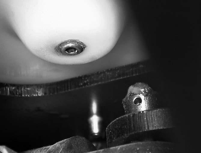
45 ESR4500 06/2004 • PRINTED IN GERMANY MS-MA-2140 HYDRAULICS MAX MIN
MS-2140-026
4 5
MS-2140-054
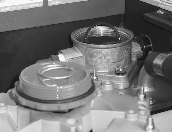
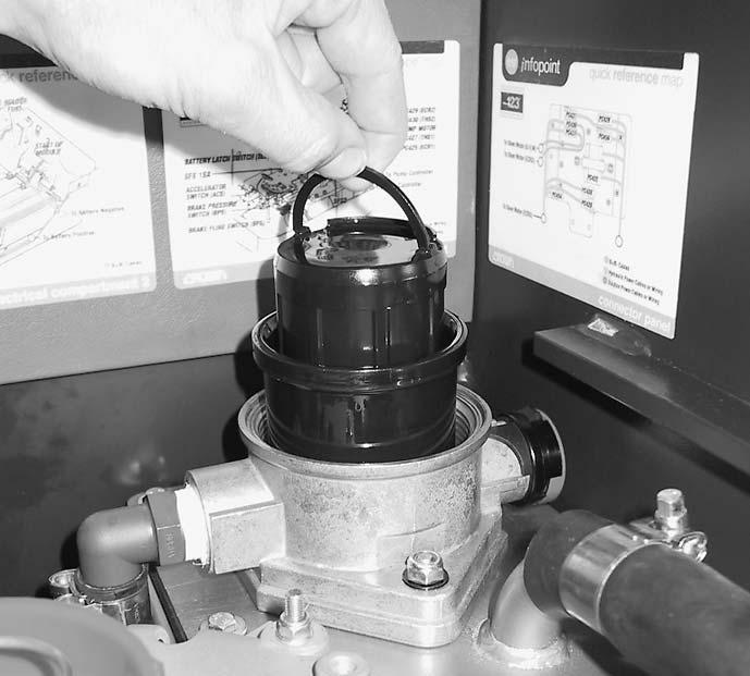
Filter
There are two large filters in the system: The return filter (1, Fig. MS-2140-053) and the suction filter (12, Fig. MS2140-069).
Replacing the Return Filter
● Turn the filter lid (5) to the left and remove it (Fig. MS-2140-049).
● Lift up the filter clip and remove the filter container (3) and the ascending tube (6), see Figs. MS-2140-062 and MS-2140-050.
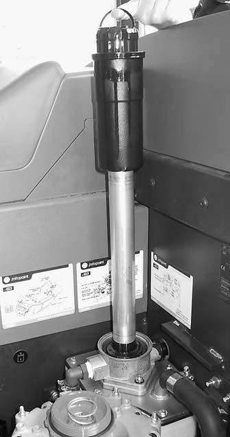
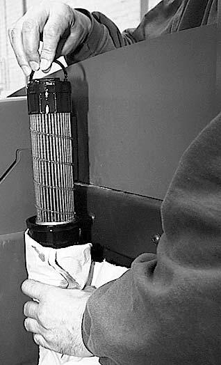
● Ensure no foreign bodies fall into the open reservoir. Do not replace the filter cartridge in the filter container when it is installed. Sediment from the filter container could enter the hydraulic oil reservoir.
● Pull the filter cartridge (1) up out of the filter container (Fig. MS-2140-053) and dispose of it in accordance with local regulations.
● Clean the filter container and the ascending tube.
● Fit a new filter cartridge in the filter container, by gently turning it down.
● Insert the new filter container and the ascending tube into the hydraulic reservoir.
● Screw the lid back onto the reservoir.
46 ESR4500 06/2004 • Printed in Germany MS-M2.0-2140 HYDRAULICS
MS-2140-049
MS-2140-062
3 3 6 1 5
MS-2140-053
7 7
MS-2140-050
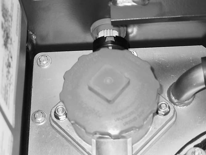
Replacing the Aeration Filter
● Unscrew the insert from the reservoir (nuts (4), Fig. MS-2140-051).
● Pull the insert (8) slightly to the left, see arrow.
● Pull off the aeration cap and the aeration filter (2).
● Replace the aeration cap and the aeration filter (= 1 component).
● Installation is the reverse of removal.
Replacing the Suction Filter
● Undo the hydraulic hoses (hose clamps (7), Fig. MS-2140-062).
● Seal all ports to prevent foreign bodies from entering.
● Undo the screws (14, Figs. MS-2140-051 and MS-2140-069).
● Remove the insert (10).
● Unscrew the filter cartridge (12).
● Replace the seal (11), if necessary.
● Installation of the new suction filter is the reverse of removal.
47 ESR4500 06/2004 • PRINTED IN GERMANY MS-MA-2140 HYDRAULICS
4 4 2 9 10 11 12 14 (7x) 4 (2x)
MS-2140-051
14 8
MS-2140-069

Pump Motor
Refer to Chapter 4 for pump motor maintenance and repair instructions.
Hydraulic Pump INFORMATION
The hydraulic pump should not be repaired on site.
For this reason it is supplied only as a complete assembly.
When commissioning a new or repaired hydraulic pump proceed as follows:
Disassembly
● Undo the union (27) from the pressure line (16) on the pump.
● Seal the pressure line ports.
● Undo the clamp (13) from the suction hose port of the reservoir.
● Pull the suction hose (14) off the reservoir.
● Seal the reservoir port and the suction hose to prevent foreign bodies from entering.
● Undo the mounting screw (25) from the connector panel (19) (Figs. MS-2140-060 and -061).
● Pull the electronics cable off the pump motor (2, Fig. MS-2140-061).
● Undo the 2 mounting screws (26) from the carrier plate (1) (Figs. MS-2140-060 and -061).
● Raise the motor and the pump until you can disassemble the pump.
● Undo the 2 mounting screws (9) from the pump (Fig. MS-2140-060).
● Pull off the pump with it exactly in line to avoid damaging the pump shaft toothing.
● Discharge the pressure line (16) connected to the pump as well as the suction line (14).
● Remove the lines from the pump.
● Fit the new pump.
● Do not yet attach the suction hose to the reservoir.
Commissioning
● Check that the assembly is clean and correctly assembled.
● Add hydraulic oil only via a 10 micron filter through the suction hose.
● Attach the suction hose to the reservoir.
● Keep the sideshift control lever in its limit position.
● Start the pump unladen and leave it to operate for a few seconds without pressure to allow for sufficient lubrication. Never run the pump without oil.
● If after 20 seconds the oil is still not free of bubbles, check the unit again.
● After reaching operating temperature check the pipe connections for leaks.
48 ESR4500 06/2004 • Printed in Germany MS-M2.0-2140
27 2 25 19 1 26
HYDRAULICS MS-2140-061
49 ESR4500 06/2004 • PRINTED IN GERMANY MS-MA-2140 HYDRAULICS 1 2 17 27 19 18 26 16 15 7 8 10 11 12 9 13 14 13 25
MS-2140-060
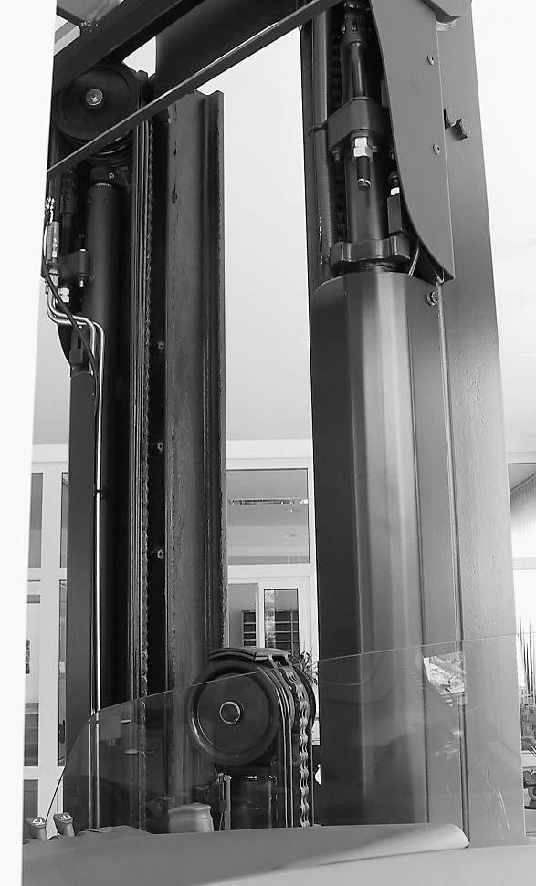
Bleeding the Hydraulic System
Whenever the hydraulic system has been opened for repairs, e.g. repairs to free lift, lift and tilt cylinders, replacing pumps or valves, you will need to bleed the system.
CAUTION
Possible damage!
On hydraulic connections with O ring seals the O rings will be damaged if opened under pressure.
Do not open connections with O ring seals for ventilation. Use only the vent screws provided on the assemblies.
Bleeding the Free Lift Cylinder
● Prepare the work area to collect spilled oil.
● Extend the free lift cylinder fully.
● Wear protective clothing, safety glasses and gloves before carrying out the next step.
● Slowly open the vent screw (SW10, 1, Fig. MS2140-052) on the free lift cylinder.
● Tighten the vent screw as soon as bubble-free oil emerges.
● Clean any oily components on the truck.
Bleeding the Lift Cylinders
● Prepare the work area to collect spilled oil.
● Extend the cylinders as far as possible.
● Wear protective clothing, safety glasses and gloves before carrying out the next step.
● Slowly open the vent screw (SW10, 2, Fig. MS2140-052) on one of the lift cylinders.
● Tighten the vent screw as soon as bubble-free oil emerges.
● Repeat the previous stages on the other lift cylinder.
● Clean any oily components on the truck.
50 ESR4500 06/2004 • Printed in Germany MS-M2.0-2140 HYDRAULICS 2 1
MS-2140-052
Bleeding the Reach Cylinder
● Extend and retract the mast reach several times until it moves without a jolt or delay.
● Hold the control lever each time at the limit position for 5 seconds.
Sealed air can flow to the other side of the cylinder piston and therefore be conducted to the reservoir.
Bleeding the Sideshift Cylinder
● Extend and retract the sideshift several times until it moves without a jolt or delay.
● Hold the control lever each time at the limit position for 5 seconds.
When the sideshift is extended as far as the stop, a connection to the “passive” cylinder chamber opens. The sealed air can be routed along here back to the reservoir.
“Bleeding the sideshift” bleeds all the hydraulic lines to the fork carriage.
Bleeding the Tilt Cylinders
Attention: The sideshift cylinders must be bled beforehand.
● Tilt the fork carriage back fully and hold the control lever at the limit position for approx. 5 seconds.
● At the same time, keep the sideshift control lever in its limit position.
● Tilt the fork carriage forward fully and hold the control lever at the limit position for approx. 5 seconds.
● At the same time, keep the sideshift control lever in its limit position.
● Repeat this process 10 times.
Bleeding the 5th Function Cylinder
See “Bleeding the tilt cylinders”
Flushing the Cylinders
After bleeding the cylinders:
● Extend the mast fully.
● Check the cylinders for leaks.
● Fully extend and retract the mast at least 10 times at max. speed up to the maximum lift height to flush the system.
51 ESR4500 06/2004 • PRINTED IN GERMANY MS-MA-2140 HYDRAULICS
HYDRAULICS
Drift Tests
After carrying out repairs to the hydraulic system perform a drift test. This is the only way of identifying internal leakage.
INFORMATION
Whenever you carry out a drift test the hydraulic oil temperature must be 3040 °C. Increase the temperature, if required, by raising below the free lift height several times.
Measure the temperature in the hydraulic reservoir before carrying out the tests. The test load should be the same as the maximum capacity (see truck capacity plate).
The test load must be evenly distributed. The load centre of gravity must be centrally located, 600 mm in front of the fork shanks, and must not exceed the capacity plate specification.
DANGER
Falling loads are hazardous! You could be fatally injured by a falling load.
Never stand underneath a raised load. Secure the test load to prevent it from slipping and falling. Set the maximum possible fork spread.
Lift cylinder drift test
● Fully extend and retract the mast several times to flush the hydraulic system.
● Raise the test load and secure it.
● Tilt the forks fully down.
● Attach a lowering plumb with a 3 m long string to the fork tip.
● Raise the test load above the free lift height until you can comfortably measure the plumb height above the ground.
● Record the height of the plumb.
● Switch off the truck and disconnect the battery.
● Wait for 10 minutes.
● Record the height of the plumb again.
● The load should lower max. 100 mm.
Tilt cylinder drift test
● Fully extend and retract the fork carriage several times from one end to the other to flush the hydraulic system.
● Raise the test load and secure it.
● Attach a lowering plumb with a 3 m long string to the fork tip. The distance from the fork shank should be 1150 mm. If not, you must convert the rated drift value accordingly.
● With the fork carriage tilted back, raise the test load above the free lift height until you can comfortably measure the plumb height above the ground.
● Record the height of the plumb.
● Switch off the truck and disconnect the battery.
● Wait for 5 minutes.
● Record the height of the plumb again.
● The difference should be max. 50 mm.
Causes of Drift
The following reasons may apply if the rated values are exceeded:
● Cylinder leaking
● Union leaking
● Foreign body in a valve seat
Repeated flushing (lifting/lowering or forward/ backward tilting at least 10 times) may remove foreign bodies from the valve seat. Now carry out the test again.
52 ESR4500 06/2004 • Printed in Germany MS-M2.0-2140
DRIVE UNIT
53 Printed in Germany
page
54 Printed in Germany
Blank
Gear unit
Preparation
Raise the truck approx. 500 mm to remove the gear unit.
See Chapter 1, Raising and Jacking up the Truck
Tools required:
● Forklift truck with sufficient capacity, lift height and fork length for the truck to be raised.
● Safety mechanism for the forks of the lifting truck, required to hold the raised truck.
● Sufficient number of wooden blocks (surface area of at least 250 x 250 mm) or suitable supports to secure the raised truck.
● Device to carry the gear unit onto a jack or pallet truck.
Removal
● Disconnect the battery and remove the key.
● Secure the truck to prevent it from being switched on again.
● Secure the truck with a second forklift and prevent it from sliding away.
DANGER
Never work underneath a suspended load.
Fatal injuries could result if the truck is suddenly lowered.
● Raise the truck until you can push a jack / pallet truck underneath the truck to support it.
● Raise the truck again by approx. 50 mm in order to be able to loosen the gear unit from the toothing at a later time.
● Lower the truck onto the wooden blocks/supports.
● Raise the device on the jack/pallet truck until it contacts the gear unit.
● Remove the electrical connections from the motor.
MS-2140-082
● Undo the six gear unit mounting screws (A) and the six motor mounting screws (B) in Fig. MS2140-082.
● Lower the device together with the gear unit and pull it out from under the truck.
Servicing
WARNING
The gear unit must only be serviced by trained and authorised Crown personnel. Failure to comply will invalidate the warranty.
Correcting the flank tooth bearing and pre-tensioning the shaft support requires years of experience with gear units. Incorrect adjustments and settings will result in premature failure of the gear unit.
It is therefore generally preferable to replace the whole gear unit.
New gear units are always supplied without oil.
Before using the gear unit for the first time, fill oil in accordance with the “LubricantTable”.
55 ESR4500 06/2004 • Printed in Germany MS-3.0-2140 DRIVE UNIT
56 ESR4500 06/2004 • Printed in Germany MS-3.0-2140 DRIVE UNIT 1 2 3 4 7 2 6 5 8 9 10 11 12 13 14 13 37 15 16 17 18 23 24 25 2 26 27 28 32 33 22 34 35 30 31 22 21 20 19 42 43 41 40 39 38 36 18 29 30 44 27
MP-2140-089
General
● All bearings and seals must be replaced.
● Prior to dismantling, thoroughly clean the gear unit with a cold cleaning solution and dry with low-pressure pressurised air.
● Use assembly equipment and a clean work area.
Gear Unit Disassembly / Assembly
All item numbers refer to Figure MP-2140-089 unless otherwise stated.
Disassembly
● Drain the oil.
● Insert the gear unit with the wheel nuts (43) into a secure device to prevent it from twisting.
● Remove the hex. socket screws (26) and the lock washers (2), take off the gear unit cover (25) and loosen the O ring (24).
● Remove the hex. socket screws (1) and the lock washers (2).
● Take off the live ring bearing (3).
● Remove the O ring (5) from the recess of the ring gear (8).
● Remove the hex. socket screws (29, 31) and the lock washers (30).
● Take off the ring gear (8).
● Remove the Allen screws (32) and the washer (33).
● Undo the hex. nut (15) of the bevel pinion shaft.
● Take the gear unit out of the device.
NOTE
When disassembling, mark the assembly location of the shims (18, 20, 35).They will have to be put back temporarily in the same position at a later stage.
● Push out the flange shaft (42) using a suitable device.
● Extract the inner ring of the conical roller bearing (38) from the flange shaft (42).
● Take the bevel gear (22), spacer ring (36) and adjusting shim(s) (18, 35) where applicable out of the housing.
● Extract the inner ring of the conical roller bearing (34) from the bevel gear (22).
● Extract the outer rings of the conical roller bearings (34, 38) from their seats in the transmission housing.
● Remove the thread shield ring (41), radial shaft seal (40) and retaining ring (39) from the housing seat.
● Press the bevel pinion shaft (22) down from out of the spur wheel (16) and the conical roller bearing (17).
● Remove the conical roller bearing (17) and shim(s) (18) where applicable.
● Extract the outer ring of the conical roller bearing (21).
● Remove the spacer bushing (19) from the bevel pinion shaft and extract the inner ring of the conical roller bearing (21) from the bevel pinion shaft.
● Thoroughly clean all components and remove the remains of the sealant and adhesive.
Assembly
NOTE
All bearings and seals must be replaced.
Preparing the gear unit
● Press the outer rings of the conical roller bearings (17, 21, 34 and 38) into their respective notches in the cleaned housing. Make sure they are positioned level in the housing.
● Insert the inner ring of the conical roller bearing (38) in the pre-assembled outer ring of the conical roller bearing (blade wheel side).
● Insert the retaining ring (39) in its corresponding groove.
57 ESR4500 06/2004 • Printed in Germany MS-3.0-2140 DRIVE UNIT
● Press the radial shaft seal (40) into the housing using a suitable tool.
● Place the thread shield ring (41) onto its space in the housing and caulk it.
● Press the inner ring of the conical roller bearing (34) onto the bevel gear (22) using a suitable tool.
● Press the wheel nuts (43) into the flange shaft holes (42) using a suitable tool.
Inserting the bevel pinion shaft
● Press the inner ring of the conical roller bearing (21) onto the conical pinion shaft (22).
● Place the shim(s) (20) and spacer bushing (19) on the conical pinion (22).
● Insert the pre-assembled bevel pinion shaft (22) into the housing (23) from below.
● Push the inner ring of the conical roller bearing (17) over the shaft of the bevel pinion shaft into the outer ring of the conical roller bearing (17).
NOTE
The spur wheel nut must be tightened with a torque wrench.
● Assemble the spur wheel (16) and torque the new hex. nut (15) to max. 100 Nm.
● Check the bevel pinion shaft for freedom of movement and make sure there is no clearance. If necessary, reduce the torque. Note the final reading. It will be required later for adjustment purposes.
Assembling the flange shaft
● Bring the housing into its later assembly position.
● Insert the spacer ring (36) and the pre-assembled bevel gear (22) in the respective order through the housing opening.
● Apply a thin layer of oil to the flange shaft (42) and carefully push it through the previously inserted unit parts in the housing.
● Insert the housing with the wheel nuts into a secure device to prevent it from twisting.
NOTE
The flange shaft assembly must be tensioned with a torque wrench.
● Guide the hex. bolts (32) through the washer (33) and torque the flange shaft assembly to max. 77 Nm.
● Check the shaft for freedom of movement and make sure there is no clearance. If necessary, reduce the torque. Note the final reading. It will be required for adjustment purposes.
Adjusting the Bevel Wheel Set
NOTE
Adjust with care. Pre-tensioning the bearings and shims will affect the tooth pattern. Do not set the pre-tension too low. it will automatically reduce during normal operation.
The correct setting can be calculated via the tooth profile pattern.
Basic Rules:
● Always adjust the bevel wheel set according to the correct flank position. The tooth ends should not form a straight line.
● The tooth pattern must always align with the inner tooth end.
● The tooth pattern must range from high (top edge of the tooth) to low (bottom edge of the tooth).
● To adjust, add and/or remove shims (18, 20, 35) or change the pre-tension of the bearings.
58 ESR4500 06/2004 • Printed in Germany MS-3.0-2140
UNIT
DRIVE
Correct tooth patterns of bevel pinion inside tooth end
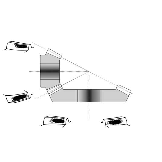
Correct tooth patterns of bevel gear inside tooth end M1565-1
Fig. M1565-1 shows the limits of the permissible tooth patterns on the bevel pinion and bevel gear.
Checking the flank tooth bearing
● Colour the tooth profiles of the bevel gear (22) with touch-up past (striking colour) or a light oil colour.
● Take the gear unit out of the device.
● Turn the bevel gear several times in one direction. The tooth bearing will appear as a bright point (marked black in Fig. M1565-1) on the tooth flanks.
● Check the tooth bearing. Remove and/or add shims (18, 20, 35) to restore the tooth bearing to the tolerance limits (Fig. M1565-1).
Attention: Torque the hex. bolts (32) and hex. nuts (15) to the previously recorded values. Repeat the process until the tooth bearing is within the tolerance limits.
Final Assembly
● Re-assemble the bevel pinion shaft and flange shaft.
● Clean all the components.
● Apply a thin layer of Loctite 307 to the inside of the conical roller bearing inner rings.
● Apply medium strength Loctite 242 (CROWN part no. 053050-006) to the threads of the hex. nuts (15) and the hex. bolts (32).
● Re-assemble as described previously.
● Manually turn the gear unit through, while checking for freedom of movement and ensure it operates without any clearance.
● Apply a thin layer of Loctite 307 to the contact surfaces of the housing cover.
● Screw the drain plug (28) with the copper ring (27) underneath it into the transmission lid (25).
● Insert the O ring (24) into the groove intended for it in the transmission lid.
● Using the hex. socket screws (26) and the lock washers (2) connect the transmission lid (25) to the housing (23). Tighten the hex. socket screws (26) and the lock washers (2) evenly and crosswise. When assembly, make sure that the oil drain opening is at the lowest point when the gear unit is subsequently installed.
● Apply a thin layer of Loctite 307 to the contact surfaces of the transmission housing to the ring gear. Fit the ring gear.
● Insert the O ring (5) into the recess of the ring gear (8).
● Fit the live ring bearing.
NOTE
Leave the surface and thread sealants to dry for at least 2 hours at room temperature before filling with oil.
● Set the gear unit in the assembly position.
● Replenish with oil up to the bottom marker of the refill plug – (for the correct oil for the application temperature see the Lubrication and Adjustment chapter).
59 ESR4500 06/2004 • Printed in Germany MS-3.0-2140 DRIVE UNIT
High Low High Low
Re-Assembly
● Assembly is the reverse of disassembly. Take care not to damage the toothing of the spur pinion (14) or the spur wheel (16).
Traction motor
Maintenance and servicing requirements for the traction motor are described in Chapter 4.
60 ESR4500 06/2004 • Printed in Germany MS-3.0-2140
UNIT
DRIVE
ELECTRICS
61 Printed in Germany
Blank page
62 Printed in Germany
Electrical Components
SPS (Safety Switch)
The safety switch is located underneath the floor board. It is connected mechanically to the safety pedal.
The operator’s foot must be on the pedal when travelling, otherwise travel and hydraulic functions will be deactivated.
The “safety switch” message is displayed if:
● the safety pedal is activated when the truck is started up
● you apply the travel switch without first applying the safety pedal
● you activate a hydraulic function without first applying the safety pedal
KYS (Key Switch)
The key switch switches on the power supply to the VCM (main truck controller).
HNS (Horn Switch)
Pressing the horn switch (horn symbol) activates the horn.
HN (Horn)
FS (Forward Switch)
This is installed in the travel direction toggle switch. It activates travel in the direction of the driver.
RS (Reverse Switch)
This is installed in the travel direction toggle switch. It activates travel in the direction of the forks.
ACS (Accelerator Switch)
Located below the accelerator pedal and activates travel.
BFS (Brake Fluid Switch)
The brake fluid switch is located in the cover of the brake fluid container. A warning is displayed when the brake fluid falls below the minimum level required.
BLS (Battery Lock Switch)
The BLS is fitted on the battery locking mechanism in the motor compartment. It monitors the locking of the battery tray when the reach is retracted. If the battery tray is not locked correctly, the truck can only be operated in creep mode.
BS
(Flashing Beacon Switch)
Installed in the control panel (overhead guard column, left of the steering wheel).
FKS (Fork Tilt Switch)
The FKS is fitted to the fork carriage. It is activated via a trip cam. It cuts out the weight display if the forks are not positioned horizontally. (The weight can only be displayed correctly if the forks are horizontal).
LS (Load Sensor)
The load sensor is fitted to the top of the tilt cylinder. It senses the weight when a load is placed on the forks. The load sensor is wired in series with the fork tilt switch.
POT1 (Traction potentiometer)
The traction potentiometer is mechanically connected to the accelerator pedal. It supplies an analog control signal to the main controller (VCM) in proportion to the position of the pedal (see A2.3). The VCM controls the travel speed via the TDM (traction module) in proportion to this control signal.
POT 1 must be recalibrated if replaced (see C1 in the Service Level menu).
POT2 (Raise potentiometer)
The raise potentiometer is mechanically connected to the Raise/Lower lever. It supplies an analog control signal to the main controller (VCM) in proportion to the position of the lever (see A2.4 in the Service Level menu). The VCM controls the lift speed via the HDM (hydraulic module) in proportion to this control signal.
POT2 must be recalibrated if replaced (see C2 in the Service Level menu).
63 ESR4500 06/2004 • Printed in GermanyMANY MS-4.1-2140 ELECTRICS Rev. 01/03
ELECTRICS
POT3 (Reach potentiometer)
The reach potentiometer is connected to the reach lever. It supplies an analog, proportional control signal to the truck controller (VCM). This governs the reach speed (see A2.5 in the Service Level menu).
POT3 must be recalibrated if replaced (see C3 in the Service Level menu).
POT4 (Tilt potentiometer)
The tilt potentiometer is connected to the tilt lever. It supplies an analog, proportional control signal to the truck controller (VCM). This governs the tilt speed (see A2.6 in the Service Level menu).
POT4 must be recalibrated if replaced (see C4 in the Service Level menu).
POT5 (Sideshift potentiometer)
The sideshift potentiometer is connected to the sideshift lever. It supplies an analog, proportional control signal to the truck controller (VCM). This governs the sideshift speed (see A2.7 in the Service Level menu).
POT5 must be recalibrated if replaced (see C5 in the Service Level menu).
POT6 (5th hydraulic function potentiometer)
The potentiometer for the 5th hydraulic function is connected to the “5th hydraulic function” lever. It supplies an analog, proportional control signal to the truck controller (VCM). This governs the speed of the 5th hydraulic function (see A2.8 in the Service Level menu).
POT6 must be recalibrated if replaced (see C6 in the Service Level menu).
PLS
(Pressure load switch)
The pressure load switch (seen in the fork direction) is located in the pipeline leading to the right-hand main lift cylinder. When a load in excess of 500 kg is being lowered, it prevents the fork carriage from stopping abruptly. This prevents the mast from swaying. The pressure load switch must be reset when replaced (to 500 kg).
SES (Seat switch)
The seat switch is located in the driver’s seat. When the driver leaves the seat, all functions are deactivated except for steering.
SFS 1SA (Forward
travel steering feedback sensor)
This switch is located in the motor compartment behind the drive motor. SFS 1SA monitors the forward position of the drive wheel.
SFS 2 (Steering feedback sensor 2)
Located in the motor compartment to the right of the drive motor. SFS2 monitors the quadrant (See Chapter 6 for an explanation of the quadrant control principle).
BRS (Parking brake switch)
The parking brake switch (next to the key switch) activates and deactivates the parking brake. When “ON” the parking brake symbol in the display lights up. When the parking brake is released the truck remains braked until you apply the accelerator pedal. This prevents the truck from rolling away.
BPS (Brake pressure switch)
The brake pressure switch is located on the brake cylinder. It is applied when a preset brake pressure is exceeded. When this pressure is exceeded, in addition to the mechanical brake an electrical braking process (with regenerative feed) is activated via the drive motor.
ORS (Override switch)
The override switch is Installed in the control panel (overhead guard column, left of the steering wheel). When you approach a programmed lift stop, you can apply the override switch to continue raising to the limit position, or to the next programmed lift stop.
ECR1 (Travel encoder)
The travel encoder consists of a sensor ball bearing in the top bearing plate of the drive motor. The travel encoder monitors the current motor speed and relays this to the TDM.
ECR2 (Lift encoder)
64 ESR4500 06/2004 • Printed in Germany MS-4.1-2140
The lift encoder is a sensor ball bearing in the top bearing plate of the pump motor. The lift encoder monitors the current motor speed and relays this to the HDM.
ECR3
(Steering feedback encoder)
The steering feedback encoder is installed in the steer motor. It feeds back a signal in proportion to the steering direction and the steering speed.
ECR4 (Steering encoder)
The steering encoder is located in the steering column below the steering wheel. When the steering wheel is turned it transmits a signal to the steer module which is based on the direction of turn and the speed of turn.
ECR5 (Height encoder)
The height encoder is located on the top cross member of the outer mast. It monitors the lift height when the free lift has been exceeded. It must be re-calibrated when replaced (see Calibration in the Service menu). Lifting is inhibited if the height encoder is faulty or if there are no height encoder signals to the VCM after 30 seconds.
THS1 (Temperature sensor 1)
THS 1 is located in the drive motor and monitors the current motor temperature. When the motor temperature reaches 145 °C, the maximum current is restricted to 250 A. If the motor temperature continues to rise, the current is reduced in proportion up to 0 A for a temperature of 165°C. At a motor temperature of 165°C and 0 A current, the motor cuts out.
THS2 (Temperature sensor 2)
THS2 is located in the hydraulic pump motor and monitors the current motor temperature. When the motor temperature reaches 145 °C, the maximum current is restricted to 250 A. If the motor temperature continues to rise, the current is reduced in proportion up to 0 A for a temperature of 165°C. At a motor temperature of 165°C and 0 A current, the motor cuts out.
THS3
(Temperature switch 3)
Switch THS3 is used only with cold store trucks. It is attached near to the accelerator pedal. The thresholds are:
ON:+2°C
OFF:+12°C
RES1 (Reach sensor 1)
SLOW Down range identified for forward/reverse reach, ”OFF“ = Reduced fwd./rev. reach
(OFF = in slow down range, ON in “normal” range)
RES1 generally activates reach speed reduction
RES2 (Reach sensor 2)
Slow Down range identified.
(ON = Slow Down rear, OFF = Slow Down front)
RES2 identifies the position of the mast in order to set off again at the appropriate speed.
(If the mast is in the Slow Down range, the speed must be reduced for Fwd. reach activation). For Rev. reach activation start again at normal reverse speed.
SVH (Lift valve)
SVR is incorporated with PVL in a single valve. SVR is a black and white valve and opens when lifting is selected. The lift speed is governed by the pump speed.
PVL (Proportional valve lower)
PVL is incorporated with SVR in a single valve. The lowering speed is governed proportionally by PVL.
65 ESR4500 06/2004 • Printed in GermanyMANY MS-4.1-2140 ELECTRICS
ELECTRICS
PVRT (Propor tional valve retract)
The retract speed is governed proportionally by PVRT. If PVRT fails, the entire hydraulic manifold block must be replaced.
PVRE (Propor tional valve extend)
The extend speed is governed proportionally by PVRE. If PVRE fails, the entire hydraulic manifold block must be replaced.
PVAR (Propor tional valve accessories right)
PVAR governs the downward tilt speed of the forks when TILT is selected, and the sideshift right speed with SIDESHIFT is selected. If PVAR fails, the entire hydraulic manifold block must be replaced.
PVAL (Proportional valve accessories left)
PVAL governs the upward tilt speed of the forks when TILT is selected, and the sideshift left speed with SIDESHIFT is selected. If PVAL fails, the entire hydraulic manifold block must be replaced.
RV (Relief valve)
RV is used to restrict the maximum operating pressure. It is set to 210 bar. RV must be reset when replaced.
MVL (Manual lowering valve)
In an emergency, MVL can be used to manually lower the fork carriage.
Close the valve again after lowering the fork carriage (turn anti-clockwise).
AVL (Lowering speed adjustment valve)
The AVL allows you to set the maximum lowering speed when PVL is fully opened.
FU1 (TDM / Display control fuse)
FU1 (15A) protects the control circuits for the traction module and the display.
FU2 (VCM / HDM control fuse)
FU2 (15A) protects the control circuits for the VCM (main controller) and the HDM (hydraulic module).
FU3 (Brake control fuse)
FU3 (15A) protects the brakes from overcurrents.
FU4 (SDM power fuse)
FU4 (30A) protects the power circuit of the steer module.
FU5 / FU6 (Options control fuses)
FU5 (15A) and FU6 (15A) protect the auxiliary options control circuits.
FU7 (Main fuse)
FU7 (425A) protects the power and control circuits for the entire truck.
FAN1 (Electric compartment fan)
This fan is optional. It can fitted subsequently if required. The fan connector (PC401) is fitted in the truck as standard.
FAN2 (traction and hydraulic module fan)
FAN2 is installed in the electric compartment below the control lever unit. This fan is temperature controlled. It switches on when the hydraulic module temperature > 35°C.
FAN3, FAN4 (Motor compartment fans)
FAN3 and FAN4 are attached to the chassis behind the hydraulic reservoir. These fans are temperature controlled. They switch on when the hydraulic module temperature > 35°C.
K1(R1-R10 Heating resistor relays)
K1 is located on the options panel. It is only used for cold store trucks. If K1 is active, heating resistors R1 to R10 are energised.
66 ESR4500 06/2004 • Printed in Germany MS-4.1-2140
K2 (Heating fan relay)
K2 is located on the options panel. It is only used for cold store trucks. A heating fan (optional) can be connected to K2.
K3 / K4 (Brake light relay)
K3 and K4 are located on the option panel. They activate the brake lights. Both relays are activated when the brake pedal is applied, as well as during inversion braking and release braking. K3 and K4 are controlled via the VCM, output CA26, pin 7.
K5
(Travel lights relay)
K5 is located on the options panel. K5 is set to position 2 via the SD switch. This activates the dipped lights, reverse lights and parking lights.
K6 (Work lights relay)
K6 is located on the options panel. K6 is activated via the SW switch. The work lights are activated via a normally open interrupteur of K6.
K7
/ K8 (Travel alarm relay)
K7 and K8 are installed in the steering column. The travel alarm is only activated if one of the available functions has been activated in Service Menu Features F8.
It is controlled by the VCM, output CA205, pin 11.
K9 / K10 (Flashing beacon relay)
K9 and K10 are installed in the steering column. The flashing beacon is only activated if one of the functions has been activated in Service Menu F9. It is controlled by the VCM, output CA205, pin 10.
K12
/ K13 (Options relay)
K12 and K13 are assembled in the electric compartment on the start up module. Both relays are only fitted for the “light package and cold store” options.
SW (Work lights
switch)
The SW switch is located in the control panel, to the left of the steering wheel. Relay K6 is controlled via the SW switch.
SD (Travel lights switch)
The SD switch is located in the control panel, to the right of the steering wheel. Switch position 1 governs the dipped lights. Switch position 2 governs relay K5. Relay K5 activates the dipped lights, reverse lights and parking lights.
SI (Indicator switch)
The SI switch is located in the control panel, to the right of the steering wheel. SI activates the indicators in the reverse lights and the dipped lights.
67 ESR4500 06/2004 • Printed in GermanyMANY MS-4.1-2140 ELECTRICS
Blank page
68 Printed in Germany
ESR4500 Status Codes
The ESR4500 is fitted with an electronic control system for the key operating functions. For certain faults the system automatically generates a service code which can be viewed on the operator display.
This maintenance section helps identify the problem when a code is encountered and provides corrective actions to help resolve the cause of the code.
Status Codes
Each of the status codes described on the following pages has a number as well as a brief description of the affected assembly and hints as to the possible causes.
When a Service Code Occurs
Generally speaking, the majority of malfunctions occur in or at output components such as solenoid valves, contactors and motors. The next most error prone components are connectors, wiring and input devices such as switches, potentiometers or encoders. The least likely to fail are the VCM (main module), TDM (traction module), HDM (hydraulic module) and SDM (steer module) control modules. In all cases, begin troubleshooting with the consumer component.
Truck does not operate and there is no Status Code
Status codes are the result of tests performed on the inputs and outputs of control signals. The malfunctions that can occur without providing a service code can fall into one of four categories.
1. Fault during power-up
Malfunctions in the power-up circuit can keep the truck from powering up. Refer to the power up circuit on the following page and the detailed description attached.
2. The fault is not electrical
The fault occurs after the truck has powered up correctly, but with no status code.
The fault is probably mechanical or hydraulic. Refer to the relevant section in the maintenance chapter of the manual.
3. Malfunction in one of a group of unmonitored inputs
One of the unmonitored inputs is causing the malfunction. These include:
HNS:Horn switch
FKS:Fork tilt switch
HGT(R)S:Height switch, height reset switch
69 ESR4500 06/2004 • Printed in GermanyMANY MS-4.3-2140 ELECTRICS
70 ESR4500 06/2004 • Printed in Germany MS-4.3-2140 ELECTRICS FU 7 = 425 A FU 1 = 15 A 48 V B+ B1+ KYS B+ FU 2 = 15 A HORN HNS BVCM HDM 28 KYS 17 CAP 24 EDS EDS (mechanical) K1 F1V1Charge-R1 C5 V5 R2 1 K11 ED1 ED1 CA 205 CA201 9 2 10 START UP CARD 4 12 3 11 V2 C1,2 14 BCA 420 A 1 C CA 420 CA402 ED1 KYS B+ B1 KYS TDM CAP CA202 18 KYS DISPLAY CA203 B+ B7 SDM CA204 8 1 2 20 19 FU 4 = 30 A B+ B-
MS-2140-022
Statuscode 100 - 102
Status Code 100
LOG BOOK display:
Überstrom in der Lenksteuerung
Over Current on Steer Drive Module
Explanation: Motor current > 49A
Effect on truck:
Possible Causes:
Status Code 101
LOG BOOK display:
- Parking brake applied
- Traction drive module deactivated
- Main contactor ED1 deactivated
- Error in module power circuit.
- If the truck is operating, this could be a nuisance code. Monitor code frequency. If necessary, inform Crown Service.
Erhöhter Strom in der Lenksteuerung
High Current Steer Drive Module
Explanation: Motor current > 27A
Effect on truck:
Possible Causes:
Status Code 102
LOG BOOK display:
Explanation:
Effect on truck:
Possible Causes:
- Parking brake applied
- Traction drive module deactivated
- Main contactor ED1 deactivated
- Error in module power circuit.
- If the truck is operating, this could be a nuisance code. Monitor code frequency. If necessary, inform Crown Service.
Fehler im Lenkmotor-Stromkreis
Error Steer Motor Circuit
Open or shorted steer motor power circuit
- Parking brake applied
- Traction drive module deactivated
- Main contactor ED1 deactivated
- Line interruption in phase R, S or T. Check power cable and motor connections, replace motor if necessary.
71 ESR4500 06/2004 • Printed in GermanyMANY MS-4.3-2140 ELECTRICS
1 0 0 X X X X X h X X X C O V E R C U R R E N T S D M 1 0 1 X X X X h X X X C H I G H C U R R E N T S D M 1 0 2 X X X X X h X X X C E R R O R S T E E R M O T X
Statuscode 110 - 120
Status Code 110
LOG BOOK display:
Überspannung an der Lenksteuerung
High Voltage Steer Drive Module
Explanation:Excess voltage in power circuit, exceeds 63 volts.
Effect on truck:
Possible Causes:
Status Code 120
LOG BOOK display:
- Hydraulic and traction drive modules deactivated
- Main contactor ED1 deactivated
- Parking brake applied
- Emergency Disconnect pressed during plugging
- Internal error in steer drive module
- If the truck is operating, this could be a nuisance code. Monitor code frequency. If necessary, inform Crown Service.
Übertemperatur in der Lenksteuerung
Over Temperature Steer Drive Module
Explanation:Temperature in steer drive module exceeds 85°C
Effect on truck: Truck brakeselectrically, then the main contactor is deactivated.
Possible Causes:
- Check the conditions of use and total service hours of the truck. If the conditions of use are arduous, check the SDM for dirt.
- - Error in control module power circuit.
- Power up the truck and press the key at the same time, enter password. Check steer motor current in menu A2.32. If the motor current exceeds 18A when the truck is idle or travelling slowly, take the following measurement.
Jack up the truck and measure current in menu A2.32. If the current is less than 5A there is no technical problem with the transmission and the toothing.
If the current remains high, replace the steer motor or the steer drive module.
- If the error persists, monitor the code frequency. If necessary, inform Crown Service.
72 ESR4500 06/2004 • Printed in Germany MS-4.3-2140 ELECTRICS
1 1 0 X X X X X h X X X C H I G H V O L T A G E S D M 1 2 0 X X X X X h X X X C O V E R T E M P S D M
Statuscode 121 - 130
Status Code 121
LOG BOOK display:
Explanation:
Effect on truck:
Possible Causes:
Erhöhte Temperatur in der Lenksteuerung High Temperature Steer Module
Temperature in steer drive module exceeds 75°C
Normal operation. Display message: Steer module hot
- Check the conditions of use and total service hours of the truck. If the conditions of use are arduous, check the SDM for dirt.
- - Error in module power circuit.
- Power up the truck and press the key at the same time, enter password.
Check steer motor current in menu A2.32. If the motor current exceeds 18A when the truck is idle or travelling slowly, take the following measurement.
Jack up the truck and measure current in menu A2.32. If the current is less than 5A there is no technical problem with the transmission and the toothing.
If the current remains high, replace the steer motor or the steer drive module.
Status Code 130
LOG BOOK display:
Explanation:
Possible Causes:
- If the error persists, monitor the code frequency. If necessary, inform Crown Service.
CAN BUS Fehler an der Lenksteuerung
Error CAN Bus Steer Module
Error in CAN BUS communication between VCM and SDM
Effect on truck: Main contactor deactivated
- Error in wire bundle or connection
- Power down truck and measure terminal resistance at PC416-1 and 2: 60 Ohm = resistance OK, 120 Ohm = a terminal resistance in VCM or SDM is faulty.
- Connect PC205 to VCM and measure resistance on VCM between PC205-22 and 23: Rated resistance = 120 Ohm. If the value is incorrect, replace VCM. If the value is correct, disconnect PC204 from SDM and measure the terminal resistance between pins 10 and 11 on the SDM. If the value is incorrect, replace SDM.
- If the truck is operating, this could be a nuisance code. Monitor code frequency. If necessary, inform Crown Service. 1 2 1 X X
73 ESR4500 06/2004 • Printed in GermanyMANY MS-4.3-2140 ELECTRICS
H I G H T E M P S D M
3 0 X X X X X h X X X C E R R O R C A N B U S S D M
X X X H X X X C
1
Statuscode 131 - 160
Status Code 131 Error
LOG BOOK display:
EEPROM Fehler an der Lenksteuerung
EEPROM Error Steer Module
Explanation: Malfunction in memory module of steer drive module
Effect on truck: None
Possible Causes: If the truck is operating, this could be a nuisance code. Monitor the code frequency, if necessary replace the steer drive module.
Status Code 160
LOG BOOK display:
Explanation:
Effect on truck:
Possible Causes:
Fehler im Parkbrems-Stromkreis Error in Brake Circuit
Open circuit or excess current on brake steer drive module output.
- Truck brought to a halt through plugging
- Traction module deactivated
- Main contactor ED1 deactivated
- Check FU3
- Check brake coil: Resistance = 55 Ohm. Replace brake if the deviation is severe
- Check lines and connections
- Clean brake and check air gap (0.5mm), adjust if necessary.
- In the event of a fault, the truck can be driven out of the working area at creep speed. The following steps must be taken: unplug and then dismantle the brake, and in menu U3.2 set ACCY = YES. This function is only active in the U3.2 menu.
74 ESR4500 06/2004 • Printed in Germany MS-4.3-2140
ELECTRICS
1 3 1 X X X X X h X X X C E R R O R E E P R O M S D M 1 6 0 X X X X X h X X X C B R A K E C O I L
Statuscode 180 - 181
Status Code 180
LOG BOOK display:
Fehler am Lenkmotor - Encoder ECR3 Error Steer Feedback Encoder ECR3
Explanation:ECR3 is a 3-channel hall sensor. An error is generated if a channel is not correctly identified or if 2 channels are short-circuited.
Effect on truck:
Possible Causes:
Status Code 181
LOG BOOK display:
- Parking brake applied
- Traction drive module deactivated
- Main contactor deactivated
- Check lines and connections
- Disconnect PC412 and check +5V between pins 4 and 6. Present: SDM OK.
Not present: Replace SDM.
- Re-connect plug. Check +5V between PC436-4 and 6. Not present: Check line.
Present: Replace motor
Fehler am Lenkencoder ECR4 Error Steer Encoder ECR4
Explanation:ECR4 is a stage motor which when applied sends an induced voltage signal to the steer drive module. An open line or short circuit are identified.
Effect on truck:
Possible Causes:
- Parking brake applied
- Traction drive module deactivated
- Main contactor deactivated
- Check lines and connections
- Disconnect PC414 and measure +5V between pin 5 or pin 2 (purple line) and BATT NEG. Present: Replace ESR4.
Not present: Check connection to SDM, replace steer drive module
75 ESR4500 06/2004 • Printed in GermanyMANY MS-4.3-2140 ELECTRICS
1 8 0 X X X X X h X X X C E C R 3 H A L L S E N S O R 1 8 1 X X X X X h X X X C E C R 4 S T E P P E R M O T
ELECTRICS
Statuscode 182 - 183
Status Code 182
LOG BOOK display:
Kein Signal SFS 1SA
No Signal SFS 1SA
1 8 2 X X X X X h X X X C S F S 1 S W E X P E C T E D
Explanation:At an angle of 0° (drive wheel forward) the sensor does not change signal as expected.
Effect on truck:
Possible Causes:
Steering error routine See chapter 6
- Set drive wheel to forward position. Now steer 20° to the left and right. Monitor the LED on the sensor. In the right position the LED is off, in the left position it is on. If there is no change: replace sensor.
- Remove sensor. Place the sensor against a metal surface and test its operation. If the LED goes on, check the mechanical setting (see chapter 6). If the LED remains off, replace the sensor. Also test the operation of the new sensor.
- No operation after replacing the sensor. Check +12V operating voltage between PC439-A and PC439-B and CA203-14 and 15 (display). No voltage present. Check lines for short circuits, replace display if necessary.
Status Code 183 Kein Signal SFS2
No Signal SFS2
LOG BOOK display:
1 8 2 X X X X X h X X X C S F S 2 S W E X P E C T E D
Explanation:Quadrant recognition error
Effect on truck: Steering error routine See chapter 6
Possible Causes:
- Set drive wheel to forward position. Now steer 90° to the left and right. Monitor the LED on the sensor. LED should always be on.
- Remove sensor. Place the sensor against a metal surface and test its operation. If the LED goes on, check the mechanical setting (see chapter 6). If the LED remains off, replace the sensor. Also test the operation of the new sensor.
- No operation after replacing the sensor. Check +12V operating voltage between PC438-A and PC438-B and CA203-14 and 15 (display). No voltage present. Check lines for short circuits, replace display if necessary.
76 ESR4500 06/2004 • Printed in Germany MS-4.3-2140
Statuscode 184 - 200
Status Code 184
LOG BOOK display:
Explanation:
Effect on truck:
Possible Causes:
Falsche Antriebsradposition erkannt
Wrong Drive Wheel position detected
Status Code 200
LOG BOOK display:
The stored value for the steering wheel does not match the current position.
Steering error routine See chapter 6
- Faulty SFS 1SA sensor.
- Set drive wheel to forward position. Now steer 20° to the left and right. Monitor the LED on the sensor. In the right position the LED is off, in the left position it is on. If there is no change: replace sensor.
- Remove sensor. Place the sensor against a metal surface and test its operation. If the LED goes on, check the mechanical setting (see chapter 6). If the LED remains off, replace the sensor. Also test the operation of the new sensor.
- No operation after replacing the sensor. Check +12V operating voltage between PC439-A and PC439-B and CA203-14 and 15 (display). No voltage present. Check lines for short circuits, replace display if necessary.
Erhöhte Stromaufnahme Hydrauliksteuerung
High Current Hydraulic Drive Module
Explanation:
Effect on truck:
Possible Causes:
Excessive current detected in power circuit (exceeds 787 A).
- Hydraulic and traction drive modules deactivated
- Main contactor ED1 deactivated
- Parking brake applied
- Short circuit in motor feed line or motor coil, or error in hydraulic drive module power circuit.
- Switch off the truck and measure the insulation resistance. If necessary replace the hydraulic motor or hydraulic drive module.
77 ESR4500 06/2004 • Printed in GermanyMANY MS-4.3-2140 ELECTRICS
1 8 4 X X X X X h X X X C S T A R T E R R O R S D M 2 0 0 X X X X X h X X X C H I G H C U R R E N T H M
Statuscode 201 - 210
Status Code 201
LOG BOOK display:
Kurzschluss Leistungskreis Hydrauliksteuerung
Short Circuit in Power Circuit Hydraulic Drive Module
Explanation: A short circuit is detected in the power circuit.
Effect on truck:
Possible Causes:
- Hydraulic and traction drive modules deactivated
- Main contactor ED1 deactivated
- Parking brake applied
- Short circuit in motor feed line or motor coil, or error in hydraulic drive module power circuit.
- Switch off the truck and measure the insulation resistance. If necessary replace the hydraulic motor or the hydraulic drive module.
Status Code 210
LOG BOOK display:
Überspannung an der Hydrauliksteuerung
High Voltage Hydraulic Module
Explanation: Excess voltage in power circuit, exceeds 63 volts.
Effect on truck:
Possible Causes:
- Hydraulic and traction drive modules deactivated
- Main contactor ED1 deactivated
- Parking brake applied
- Emergency Disconnect pressed during plugging
- Internal error in traction drive module
- If the truck is operating, this could be a nuisance code. Monitor code frequency. If necessary, inform Crown Service.
78 ESR4500 06/2004 • Printed in Germany MS-4.3-2140
ELECTRICS
2 0 1 X X X X X . X h X X X C S H O R T C I R C U I T H M 2 1 0 X X X X X h X X X C H I G H V O L T A G E H M
Statuscode 211 - 213
Status Code 211
LOG BOOK display:
Unterspannung an der Hydrauliksteuerung Low Voltage Hydraulic Module
Explanation: The hydraulic drive module has detected a voltage below 18 volts.
Effect on truck:
Possible Causes:
- Hydraulic and traction drive modules deactivated
- Main contactor ED1 deactivated
- Parking brake applied
- Check power circuit wiring
- Faulty battery. Battery voltage collapses under load. Select menu item A.2.36, lift a heavy load and monitor the battery voltage during lifting.
- Check battery cell voltages. If necessary, replace battery.
Status Code 212 15 Volt Spannungsversorgung zu niedrig 15 Volt Supply to low
LOG BOOK display:
Explanation:
Effect on truck:
Possible Causes:
Status Code 213
LOG BOOK display:
Explanation:
Effect on truck:
Internal error in hydraulic drive module 15 volt supply for the pulse width modulation (PWM) of the line transistors is faulty
- Hydraulic drive module is deactivated - Truck can operate in creep mode.
Internal error, replace control module.
5 Volt Spannungsversorgung zu niedrig 5 Volt Supply to low
Internal error in hydraulic drive module 5 volt supply for internal current measurement in power circuit.
- Hydraulic drive module is deactivated - Truck can operate in creep mode.
Possible Causes: Internal error, replace control module.
79 ESR4500 06/2004 • Printed in GermanyMANY MS-4.3-2140 ELECTRICS
2 1 1 X X X X X h X X X C L O W V O L T A G E H M 2 1 2 X X X X X X h X X X C 1 5 V O L T S U P P L Y H M 2 1 3 X X X X X h X X X C 5 V O L T S U P P L Y H M
Statuscode 214 - 220
Status Code 214
LOG BOOK display:
Hydrauliksteuerung: Kondensatorladezeit überschritten Hydraulic Drive Module: Capacitor Charge exceeded
Explanation: Capacitors are not charged.
Effect on truck:
Possible Causes:
Status
Code 220
LOG BOOK display:
Explanation:
Effect on truck:
Possible Causes:
- Main contactor is not activated
- No battery voltage on B+ input of hydraulic drive module
- Connect measuring device between B+ and B- on the hydraulic drive module and power up the truck. The voltage at B+ should rise from 0V within approx. 2s. If not, check the lines.
- If the voltage is applied, there is an internal error in the hydraulic drive module. Replace the module
Übertemperatur in der Hydrauliksteuerung Over Temperature Hydraulic Drive Module
Temperature in hydraulic drive module exceeds 115°C
- Hydraulic drive module is deactivated
- Truck can operate in creep mode.
- Error message displayed. Hydraulic module hot
- Check the conditions of use and total service hours of the truck.
- If the truck does not operate in arduous conditions, check the fans
- In menu A1.9 monitor the hydraulic drive module temperature and continually apply one of the hydraulic functions to bring the module to operating temperature. When the temperature exceeds 35°C all the fans should start up. CA201-2 is set to BATT NEG.
- If there is no operation: Check fans, lines, connections and power supply.
- Remove TDM and HDM and check radiator fins are clean. Clean if necessary.
- If the error persists, monitor the code frequency. If necessary, inform Crown Service.
80 ESR4500 06/2004 • Printed in Germany MS-4.3-2140
ELECTRICS
2 1 4 X X X X X h X X X C C A P C H A R G E H M 2 2 0 X X X X X h X X X C O V E R T E M P H M
Statuscode 221 - 222
Status Code 221
LOG BOOK display:
Explanation:
Effect on truck:
Possible Causes:
Übertemperatur
am
Hydraulikmotor
Over Temperature Hydraulic Motor
2 2 1 X X X X X h X X X C
Temperature in motor coil exceeds 165°C
- Hydraulic drive module is deactivated
- Truck can operate in creep mode.
- Error message displayed. Hydraulic motor hot
- Check the conditions of use and total service hours of the truck.
- If the truck does not operate in arduous conditions, check the fans
- In menu A1.9 monitor the hydraulic drive module temperature and continually apply one of the hydraulic functions to bring the module to operating temperature. When the temperature exceeds 35°C all the fans should start up. CA201-2 is set to BATT NEG.
- If there is no operation: Check fans, lines, connections and power supply.
- Remove TDM and HDM and check radiator fins are clean. Clean if necessary.
- If the error persists, monitor the code frequency. If necessary, inform Crown Service.
Status Code 222
LOG BOOK display:
Explanation:
Effect on truck:
Possible Causes:
Erhöhte Temperatur an der Hydrauliksteuerung High Temperature Hydraulic Drive Module
Temperature in hydraulic drive module exceeds 85°C
- Hydraulic drive module current is linearly reduced to 0 A between 85° and 115°C.
- Error message displayed. Hydraulic module hot
- Check the conditions of use and total service hours of the truck.
- If the truck does not operate in arduous conditions, check the fans
- In menu A1.9 monitor the hydraulic drive module temperature and continually apply one of the hydraulic functions to bring the module to operating temperature. When the temperature exceeds 35°C all the fans should start up. CA201-2 is set to BATT NEG.
- If there is no operation: Check fans, lines, connections and power supply.
- Remove TDM and HDM and check radiator fins are clean. Clean if necessary.
- If the error persists, monitor the code frequency. If necessary, inform Crown Service.
81 ESR4500 06/2004 • Printed in GermanyMANY MS-4.3-2140 ELECTRICS
O
T E M P H M O T
X X X h X X X C H I G H T E M P H M
V E R
2 2 2 X X
Statuscode 223 - 224
Status Code 223
LOG BOOK display:
Temperatur zu tief an der Hydrauliksteuerung Low Temperature Hydraulic Module
Explanation: Temperature in hydraulic drive module is less than –20°C
Effect on truck: Error message displayed. Hydraulic module cold
Possible Causes: Check the conditions of use and total service hours of the truck. Attention: The truck has been stored in a cold environment for a long period of time.
Status
Code 224
LOG BOOK display:
Erhöhte Temperatur am Hydraulikmotor High Temperature Hydraulic Motor
Explanation: Temperature in motor coil exceeds 145°C
Effect on truck: Motor current is linearly reduced to 0 A between 145° and 165°C motor temperature.
Possible Causes:
Error message displayed. Hydraulic motor hot
- Check the conditions of use and total service hours of the truck.
- If the truck does not operate in arduous conditions, check the fans
- In menu A1.9 monitor the hydraulic drive module temperature and continually apply one of the hydraulic functions to bring the module to operating temperature. When the temperature exceeds 35° all the fans should start up. CA201-2 is set to BATT NEG.
- If there is no operation: Check fans, lines, connections and power supply.
- Remove TDM and HDM and check radiator fins are clean. Clean if necessary.
- If the error persists, monitor the code frequency. If necessary, inform Crown Service.
82 ESR4500 06/2004 • Printed in Germany MS-4.3-2140
ELECTRICS
2 2 3 X X X X X h X X X C L O W T E M P H M 2 2 4 X X X X X h X X X C H I G H T E M P H M O T
Statuscode 225 - 230
Status Code 225
LOG BOOK display:
Temperatur zu tief am Hydraulikmotor Low Temperature Hydraulic Motor
Explanation: Temperature in motor coil is less than –30°C
Effect on truck: Error message displayed. Hydraulic motor cold
Possible Causes:
Status Code 230
LOG BOOK display:
Explanation:
Effect on truck:
Possible Causes:
Check the conditions of use and total service hours of the truck. Attention: The truck has been stored in a cold environment for a long period of time.
CAN BUS Fehler an der Hydrauliksteuerung Error CAN BUS Hydraulic Drive Module
Error in CAN BUS communication between VCM and SDM
Main contactor deactivated
- Error in wire bundle or connection
- Power down truck and measure terminal resistance at PC416-1 and 2: 60 Ohm = resistance OK, 120 Ohm = a terminal resistance in VCM or SDM is faulty.
- Connect PC205 to VCM and measure resistance on VCM between PC205-22 and 23: Rated resistance = 120 Ohm. If the value is incorrect, replace VCM. If the value is correct, disconnect PC204 from SDM and measure the terminal resistance between pins 10 and 11 on the SDM. If the value is incorrect, replace SDM.
- If the truck is operating, this could be a nuisance code. Monitor code frequency. If necessary, inform Crown Service.
83 ESR4500 06/2004 • Printed in GermanyMANY MS-4.3-2140 ELECTRICS
5 X X X X X h X X X C L O W T E M P H M O T
3 0 X X X X X h X X X C E R R O R C A N B U S H M
2 2
2
Statuscode 240
Status Code 240
LOG BOOK display:
Eingangsspannung von POT2 über dem Grenzwert Input Voltage from POT2 above Limit
2 4 0 X X X X X h X X X C
P O T 2 A B O V E L I M I T
Explanation: The loop voltage from POT2 is continually monitored during start-up and operation. The upper limit of 10.8 volt is exceeded during this time.
Effect on truck: Hydraulic function completely disabled.
Possible Causes:
- Select menu item A2.4 (POT2). Activate “Raise/Lower”.
- Take readings from display.
Approx. 12V: Short circuit between potentiometer CA407-2 (red) and CA407-1 (green). Check reading with a digital multimeter. Reading confirmed: Replace potentiometer, check wiring.
Approx. 5.0 – 6.0 V: correct reading when control lever is in neutral.
0.7 – 1.5 V: correct reading when control lever is in max “Lower” position.
9.5 – 10.5 V: correct reading when control lever is in max “Raise” position.
If the readings are correct, there is probably an intermittent fault in the potentiometer circuit. Check wire connections and potentiometer.
Note: Recalibrate potentiometer after carrying out repairs
84 ESR4500 06/2004 • Printed in Germany MS-4.3-2140
ELECTRICS
Statuscode 241
Status Code 241
LOG BOOK display:
Eingangsspannung von POT2 ist unter dem Grenzwert Input Voltage from POT2 under Limit
2 4 1 X X X X X h X X X C
Explanation:The loop voltage from POT2 is continually monitored during start-up and operation. The lower limit of 0.6 volt is exceeded during this time.
Effect on truck:
Hydraulic function completely disabled.
Possible Causes:-Selectmenu item A2.4 (POT2). Activate “Raise/Lower”.
- Takereadings from display.
Approx. 0 V: open circuit between potentiometer CA407-2 (red), CA407-1 (green) and VCM or short circuit between CA407-2 (red) and CA407-3 (yellow).
Check connection PC407 and PC205. If the wiring is ok, replace the potentiometer.
Approx. 5.0 – 6.0 V: correct reading when control lever is in neutral.
0.7 – 1.5 V: correct reading when control lever is in max “Lower” position.
9.5 – 10.5 V: correct reading when control lever is in max “Raise” position.
If the readings are correct, there is probably an intermittent fault in the potentiometer circuit. Check wire connections and potentiometer.
Note: Recalibrate potentiometer after carrying out repairs
85 ESR4500 06/2004 • Printed in GermanyMANY MS-4.3-2140 ELECTRICS
P O T 2 U N D E R L I M I T
Statuscode 243
Status Code 243
LOG BOOK display:
Eingangsspannung von POT3 über dem Grenzwert Input Voltage from POT3 above Limit
Explanation: The loop voltage from POT3 is continually monitored during start-up and operation. The upper limit of 10.8 volt is exceeded during this time.
Effect on truck: Hydraulic function completely disabled.
Possible Causes:
- Select menu item A2.5 (POT3). Activate “Reach” function.
- Take readings from display.
Note: Recalibrate potentiometer after carrying out repairs 2 4 3 X X X X X h X X X C
Approx. 12V: Short circuit between potentiometer CA408-2 (red) and CA408-1 (green). Check reading with a digital multimeter. Reading confirmed: Replace potentiometer, check wiring.
Approx. 5.0 – 6.0 V: correct reading when control lever is in neutral.
0.7 – 1.5 V: correct reading when control lever is in max “Fwd. Reach” position.
9.5 – 10.5 V: correct reading when control lever is in max “Rev. Reach” position.
If the readings are correct, there is probably an intermittent fault in the potentiometer circuit. Check wire connections and potentiometer.
86 ESR4500 06/2004 • Printed in Germany MS-4.3-2140
ELECTRICS
P O T 3 A B O V E L I M I T
Statuscode 244
Status Code 244
LOG BOOK display:
Eingangsspannung von POT3 unter dem Grenzwert Input Voltage from POT3 under Limit
Explanation:The loop voltage from POT3 is continually monitored during start-up and operation. The lower limit of 0.6 volt is exceeded during this time.
Effect on truck: Hydraulic function completely disabled.
Possible Causes:-Selectmenu item A2.5 (POT3). Activate “Reach” function.
- Takereadings from display.
Note: Recalibrate potentiometer after carrying out repairs 2 4 4 X X X X X h X X X C
Approx. 0 V: open circuit between potentiometer CA408-2 (red), CA408-1 (green) and VCM or short circuit between CA408-2 (red) and CA408-3 (yellow).
Check connection PC408 and PC205. If the wiring is ok, replace the potentiometer.
Approx. 5.0 – 6.0 V: correct reading when control lever is in neutral.
0.7 – 1.5 V: correct reading when control lever is in max “Fwd. Reach” position.
9.5 – 10.5 V: correct reading when control lever is in max “Rev. Reach” position.
If the readings are correct, there is probably an intermittent fault in the potentiometer circuit. Check wire connections and potentiometer.
87 ESR4500 06/2004 • Printed in GermanyMANY MS-4.3-2140 ELECTRICS
P
U N D E R L I M I T
O T 3
Statuscode 246
Status Code 246
LOG BOOK display:
Eingangsspannung von POT4 über dem Grenzwert Input Voltage from POT4 above Limit
2 4 6 X X X X X h X X X C P O T 4 A B O V E L I M I T
Explanation: The loop voltage from POT4 is continually monitored during start-up and operation. The upper limit of 10.8 volt is exceeded during this time.
Effect on truck: Hydraulic function completely disabled.
Possible Causes:
- Select menu item A2.6 (POT4). Activate “Fork tilt” function. - Take readings from display.
Approx. 12V: Short circuit between potentiometer CA409-2 (red) and CA409-1 (green). Check reading with a digital multimeter. Reading confirmed: Replace potentiometer, check wiring.
Approx. 5.0 – 6.0 V: correct reading when control lever is in neutral.
0.7 – 1.5 V: correct reading when control lever is in max “Fork tilt down” position.
9.5 – 10.5 V: correct reading when control lever is in max “Fork tilt up” position.
If the readings are correct, there is probably an intermittent fault in the potentiometer circuit. Check wire connections and potentiometer.
Note: Recalibrate potentiometer after carrying out repairs
88 ESR4500 06/2004 • Printed in Germany MS-4.3-2140
ELECTRICS
Statuscode 247
Status Code 247
LOG BOOK display:
Eingangsspannung von POT4 unter dem Grenzwert Input Voltage from POT4 under Limit
2 4 7 X X X X X h X X X C
Explanation:The loop voltage from POT4 is continually monitored during start-up and operation. The lower limit of 0.6 volt is exceeded during this time.
Effect on truck: Hydraulic function completely disabled.
Possible Causes:-Selectmenu item A2.6 (POT4). Activate “Fork tilt” function.
- Takereadings from display.
Approx. 0 V: open circuit between potentiometer CA409-2 (red), CA409-1 (green) and VCM or short circuit between CA409-2 (red) and CA409-3 (yellow).
Check connection PC409 and PC205. If the wiring is ok, replace the potentiometer.
Approx. 5.0 – 6.0 V: correct reading when control lever is in neutral.
0.7 – 1.5 V: correct reading when control lever is in max “Fork tilt down” position.
9.5 – 10.5 V: correct reading when control lever is in max “Fork tilt up” position.
If the readings are correct, there is probably an intermittent fault in the potentiometer circuit. Check wire connections and potentiometer.
Note: Recalibrate potentiometer after carrying out repairs
89 ESR4500 06/2004 • Printed in GermanyMANY MS-4.3-2140 ELECTRICS
P O T 4 U N D E R L I M I T
Statuscode 249
Status Code 249
LOG BOOK display:
Eingangsspannung von POT5 über dem Grenzwert Input Voltage from POT5 above Limit
2 4 9 X X X X X h X X X C P O T 5 A B O V E L I M I T
Explanation: The loop voltage from POT5 is continually monitored during start-up and operation. The upper limit of 10.8 volt is exceeded during this time.
Effect on truck: Hydraulic function completely disabled.
Possible Causes:
- Select menu item A2.7 (POT5). Activate “Sideshift” function.
- Take readings from display.
Approx. 12V: Short circuit between potentiometer CA410-2 (red) and CA410-1 (green). Check reading with a digital multimeter. Reading confirmed: Replace potentiometer, check wiring.
Approx. 5.0 – 6.0 V: correct reading when control lever is in neutral.
0.7 – 1.5 V: correct reading when control lever is in max “Sideshift left” position.
9.5 – 10.5 V: correct reading when control lever is in max “Sideshift right” position.
If the readings are correct, there is probably an intermittent fault in the potentiometer circuit. Check wire connections and potentiometer.
Note: Recalibrate potentiometer after carrying out repairs
90 ESR4500 06/2004 • Printed in Germany MS-4.3-2140
ELECTRICS
Statuscode 250
Status Code 250
LOG BOOK display:
Eingangsspannung von POT5 unter dem Grenzwert Input Voltage from POT5 under Limit
2 5 0 X X X X X h X X X C
Explanation:The loop voltage from POT5 is continually monitored during start-up and operation. The lower limit of 0.6 volt is exceeded during this time.
Effect on truck: Hydraulic function completely disabled.
Possible Causes:-Selectmenu item A2.7 (POT5). Activate “Sideshift” function.
- Takereadings from display.
Approx. 0 V: open circuit between potentiometer CA410-2 (red), CA410-1 (green) and VCM or short circuit between CA410-2 (red) and CA410-3 (yellow).
Check connection PC410 and PC205. If the wiring is ok, replace the potentiometer.
Approx. 5.0 – 6.0 V: correct reading when control lever is in neutral.
0.7 – 1.5 V: correct reading when control lever is in max “Sideshift left” position.
9.5 – 10.5 V: correct reading when control lever is in max “Sideshift right” position.
If the readings are correct, there is probably an intermittent fault in the potentiometer circuit. Check wire connections and potentiometer.
Note: Recalibrate potentiometer after carrying out repairs
91 ESR4500 06/2004 • Printed in GermanyMANY MS-4.3-2140 ELECTRICS
P
U
D E R L I M I T
O T 5
N
Statuscode 252
Status Code 252
LOG BOOK display:
Eingangsspannung von POT6 über dem Grenzwert Input Voltage from POT6 above Limit
2 5 2 X X X X X h X X X C P O T 6 A B O V E L I M I T
Explanation: The loop voltage from POT6 is continually monitored during start-up and operation. The upper limit of 10.8 volt is exceeded during this time.
Effect on truck: Hydraulic function completely disabled.
Possible Causes:
- Select menu item A2.8 (POT6). Apply 5th function.
- Take readings from display.
Approx. 12V: Short circuit between potentiometer CA411-2 (red) and CA411-1 (green). Check reading with a digital multimeter. Reading confirmed: Replace potentiometer, check wiring.
Approx. 5.0 – 6.0 V: correct reading when control lever is in neutral.
0.7 – 1.5 V: correct reading when control lever is in max “5th function left” position.
9.5 – 10.5 V: correct reading when control lever is in max “5th function right” position.
If the readings are correct, there is probably an intermittent fault in the potentiometer circuit. Check wire connections and potentiometer.
Note: Recalibrate potentiometer after carrying out repairs
92 ESR4500 06/2004 • Printed in Germany MS-4.3-2140
ELECTRICS
Statuscode 253
Status Code 253
LOG BOOK display:
Eingangsspannung von POT6 unter dem Grenzwert Input Voltage from POT6 under Limit
2 5 3 X X X X X h X X X C P O T 6 U N D E R L I M I T
Explanation:The loop voltage from POT6 is continually monitored during start-up and operation. The lower limit of 0.6 volt is exceeded during this time.
Effect on truck: Hydraulic function completely disabled.
Possible Causes:-Selectmenu item A2.8 (POT6). 5. Activate function.
- Takereadings from display.
Approx. 0 V: open circuit between potentiometer CA411-2 (red), CA411-1 (green) and VCM or short circuit between CA411-2 (red) and CA411-3 (yellow).
Check connection PC411 and PC205. If the wiring is ok, replace the potentiometer.
Approx. 5.0 – 6.0 V: correct reading when control lever is in neutral.
0.7 – 1.5 V: correct reading when control lever is in max “5th function left” position.
9.5 – 10.5 V: correct reading when control lever is in max “5th function right” position.
If the readings are correct, there is probably an intermittent fault in the potentiometer circuit. Check wire connections and potentiometer.
Note: Recalibrate potentiometer after carrying out repairs
93 ESR4500 06/2004 • Printed in GermanyMANY MS-4.3-2140 ELECTRICS
Statuscode 260
Status Code 260
LOG BOOK display:
Kurzschluss SVH (Hubventil)
Short Circuit SVH (Lift Valve)
2 6 0 X X X X X h X X X C
S V H L I F T V A L V E
Explanation:On the VCM main controller an overcurrent is detected on the SVH output during lifting and the contactor output is cut out.
Effect on truck:
Possible Causes:
- Hydraulic valves are cut out - Pump continues to operate.
Check coil resistance
- Disconnect PC807 connector from solenoid valve. Connect measuring device between pins 2 and 3 to the SVH and measure the coil resistance. Resistance = 75 Ohm.
- If the coil resistance is excessive or 0 ohms, SVH must be replaced.
Missing Positive Test
- Power up the truck and record the voltage between PC422-9 and the battery negative. Battery voltage should be applied.
- Disconnect PC807 from the solenoid valve and record the voltage between PC422-9 and the battery negative. If battery positive is still applied, there is a short circuit between PC8073 and PC205-1 against the battery positive. After recording, re-connect PC807.
- Power up the truck and connect the measuring device between PC4229 and the battery negative. Without applying POT2 (raise/lower) battery positive should be applied. When activating POT2 (raise) the voltage should drop to approx. 15 volt. If not, replace the VCM.
94 ESR4500 06/2004 • Printed in Germany MS-4.3-2140
ELECTRICS
Status Code 261
LOG BOOK display:
Kurzschluss PVL (Absenkventil)
Short Circuit PVL (Lower Valve)
Explanation:On the VCM main controller an overcurrent is detected on the PVL output during lifting and the contactor output is cut out.
Effect on truck:
Possible Causes:
- Hydraulic valves are cut out - Pump continues to operate.
Check coil resistance
Disconnect PC807 connector from solenoid valve. Connect measuring device between pins 1 and 2 to PVL and measure the coil resistance. Resistance = 27 Ohm. If the coil resistance is excessive or 0 ohms, PVL must be replaced.
Missing Positive Test
- Power up the truck and record the voltage between PC422-8 and the battery negative. Battery voltage should be applied.
- Disconnect PC807 from the solenoid valve and record the voltage between PC422-8 and the battery negative. If battery positive is still applied, there is a short circuit between PC8071 and PC205-42 against the battery positive. After recording, re-connect PC807.
- Power up the truck and connect the measuring device between PC4229 and the battery negative. Without applying POT2 (raise/lower) battery positive should be applied. When activating POT2 (lower) the voltage should drop to approx. 33 volt. If not, replace the VCM. 2 6 1 X X X X X h X X X C
95 ESR4500 06/2004 • Printed in GermanyMANY MS-4.3-2140 ELECTRICS
V A L
P V L L O W E R
V E Statuscode 261
Statuscode 262
Status Code 262
LOG BOOK display:
Kurzschluss PVRT (Ventil Mastvorschub zurück)
Short Circuit PVRT (Retract Valve)
Explanation:On the VCM main controller an overcurrent is detected on the PVRT output during a reach operation and the contactor output is cut out.
Effect on truck:
- Hydraulic valves are cut out - Pump continues to operate.
Possible Causes: Check coil resistance
Disconnect PC810 connector from solenoid valve. Connect measuring device between pins 1 and 2 to PVRT and measure the coil resistance. Resistance = 25 Ohm. If the coil resistance is excessive or 0 ohms, PVRT must be replaced.
Missing Positive Test
- Power up the truck and record the voltage between PC422-16 and the battery negative. Battery voltage should be applied.
- Disconnect PC810 from the solenoid valve and record the voltage between PC422-16 and the battery negative. If battery positive is still applied, there is a short circuit between PC8102 and PC205-29 against the battery positive. After recording, re-connect PC810.
- Power up the truck and connect the measuring device between PC42216 and the battery negative. Without applying POT3 (fwd. reach) battery positive should be applied. When activating POT3 (rev. reach) the voltage should drop to approx. 35 volt. If not, replace the VCM. 2
96 ESR4500 06/2004 • Printed in Germany MS-4.3-2140
ELECTRICS
X h
P V R T R E T R A C T V A
6 2 X X X X
X X X C
Statuscode 263
Status Code 263
LOG BOOK display:
Kurzschluss PVRE (Ventil Mastvorschub vor)
Short Circuit PVRE (Reach Valve)
Explanation:On the VCM main controller an overcurrent is detected on the PVRE output during a reach operation and the contactor output is cut out.
Effect on truck:
Possible Causes:
- Hydraulic valves are cut out - Pump continues to operate.
Check coil resistance
Disconnect PC808 connector from solenoid valve. Connect measuring device between pins 1 and 2 to PVRE and measure the coil resistance. Resistance = 25 Ohm.
If the coil resistance is excessive or 0 ohms, PVRE must be replaced.
Missing Positive Test
- Power up the truck and record the voltage between PC422-10 and the battery negative. Battery voltage should be applied.
- Disconnect PC808 from the solenoid valve and record the voltage between PC422-10 and the battery negative. If battery positive is still applied, there is a short circuit between PC8082 and PC205-15 against the battery positive. After recording, re-connect PC808.
- Power up the truck and connect the measuring device between PC42210 and the battery negative. Without applying POT3 (reach) battery positive should be applied. When activating POT3 (fwd. reach) the voltage should drop to approx. 31 volt. If not, replace the VCM.
97 ESR4500 06/2004 • Printed in GermanyMANY MS-4.3-2140 ELECTRICS
2 6 3 X X X X X h X X X C P V R E R E A C H V A L V E
Statuscode 264
Status Code 264
LOG BOOK display:
Kurzschluss PVAL (Ventil Zusatzfunktionen links)
Short Circuit PVAL (Accessory Valve Left)
Explanation:On the VCM main controller an overcurrent is detected on the PVAL output during an auxiliary operation and the contactor output is cut out.
Effect on truck: - Hydraulic valves are cut out - Pump continues to operate.
Possible Causes: Check coil resistance
Disconnect PC809 connector from solenoid valve. Connect measuring device between pins 1 and 2 to PVAL and measure the coil resistance. Resistance = 25 Ohm.
If the coil resistance is excessive or 0 ohms, PVAR must be replaced.
Missing Positive Test
- Power up the truck and record the voltage between PC422-12 and the battery negative. Battery voltage should be applied.
- Disconnect PC809 from the solenoid valve and record the voltage between PC422-12 and the battery negative. If battery positive is still applied, there is a short circuit between PC8092 and PC205-13 against the battery positive. After recording, re-connect PC809.
- Power up the truck and connect the measuring device between PC42216 and the battery negative.
Without activating POT4 (fork tilt up) orPOT5 (sideshift left), battery positive should be applied. When activating POT4 (fork tilt up) the voltage should drop to approx. 29 volt. If not, replace the VCM.
98 ESR4500 06/2004 • Printed in Germany MS-4.3-2140
ELECTRICS
X X X X X h X X X C P V A L A C C E S S O R Y L
2 6 4
Statuscode 265
Status Code 265
LOG BOOK display:
Kurzschluss PVAR (Ventil Zusatzfunktionen rechts)
Short Circuit PVAR (Accessory Valve Right)
Explanation:On the VCM main controller an overcurrent is detected on the PVAR output during an auxiliary operation and the contactor output is cut out.
Effect on truck:
Possible Causes:
- Hydraulic valves are cut out - Pump continues to operate.
Check coil resistance
Disconnect PC811 connector from solenoid valve. Connect measuring device between pins 1 and 2 to PVAR and measure the coil resistance. Resistance = 25 Ohm.
If the coil resistance is excessive or 0 ohms, PVAR must be replaced.
Missing Positive Test
- Power up the truck and record the voltage between PC422-11 and the battery negative. Battery voltage should be applied.
- Disconnect PC811 from the solenoid valve and record the voltage between PC422-11 and the battery negative. If battery positive is still applied, there is a short circuit between PC8112 and PC205-27 against the battery positive. After recording, re-connect PC811.
- Power up the truck and connect the measuring device between PC42211 and the battery negative.
Without activating POT4 (fork tilt down) or POT5 (sideshift right), battery positive should be applied.
When activating POT4 (fork tilt down) the voltage should drop to approx. 29 volt. If not, replace the VCM.
99 ESR4500 06/2004 • Printed in GermanyMANY MS-4.3-2140 ELECTRICS
6 5 X X X X X h X X X C P V A R A C C E S S O R Y R
2
ELECTRICS
Statuscode 266
Status Code 266
LOG BOOK display:
Kurzschluss SVT (Magnetventil Neigen)
Short Circuit SVT (Tilt Valve)
2 6 6 X X X X X h X X X C
S V T T I L T V A L V E
Explanation:On the VCM main controller an overcurrent is detected on the SVT output during a tilt operation and the contactor output is cut out.
Effect on truck:
Possible Causes:
- Hydraulic valves are cut out - Pump continues to operate.
Check coil resistance
Disconnect PC801 connector from fork carriage. Connect measuring device between pins 1 and 2 to connector PC801 and measure the coil resistance. Resistance = 39 Ohm. If the coil resistance is excessive or 0 ohms, SVT must be replaced.
Missing Positive Test
- Power up the truck and record the voltage between PC422-1 and the battery negative. Battery voltage should be applied.
- Disconnect PC801 from the solenoid valve and record the voltage between PC422-1 and the battery negative. If battery positive is still applied, there is a short circuit between PC8011 and PC205-41 against the battery positive. After recording, re-connect PC801.
- Power up the truck and connect the measuring device between PC4221 and the battery negative. Without applying POT4 (tilt) battery positive should be applied. When activating POT4 the voltage should drop to approx. 15 volt. If not, replace the VCM.
100 ESR4500 06/2004 • Printed in Germany MS-4.3-2140
Status Code 267Kurzschluss SVS (Magnetventil Seitenschieber) Short Circuit SVS (Side Shift Valve)
LOG BOOK display:
Explanation:On the VCM main controller an overcurrent is detected on the SVS output during sideshifting and the contactor output is cut out.
Effect on truck:
Possible Causes:
- Hydraulic valves are cut out - Pump continues to operate.
Check coil resistance
Disconnect PC801 connector from fork carriage. Connect measuring device between pins 5 and 6 to connector PC801 and measure the coil resistance. Resistance = 39 Ohm. If the coil resistance is excessive or 0 ohms, SVS must be replaced.
Missing Positive Test
- Power up the truck and record the voltage between PC422-5 and the battery negative. Battery voltage should be applied.
- Disconnect PC801 from the solenoid valve and record the voltage between PC422-5 and the battery negative. If battery positive is still applied, there is a short circuit between PC8015 and PC205-12 against the battery positive. After recording, re-connect PC801.
- Power up the truck and connect the measuring device between PC4225 and the battery negative. Without applying POT5 (sideshift) battery positive should be applied. When activating POT5 the voltage should drop to approx. 15 volt. If not, replace the VCM. 2 6 7 X X X X X h X X X C
101 ESR4500 06/2004 • Printed in GermanyMANY MS-4.3-2140 ELECTRICS
S
D E S H I F T V
V S S I
Statuscode 267
ELECTRICS
Statuscode 268
Status Code 268
LOG BOOK display:
Kurzschluss SV5 (Magnetventil 5. Funktion) Short Circuit SV5 (5th Function Valve)
2 6 8 X X X X X h X X X C
S V 5 5 T H F U N C V A
Explanation:On the VCM main controller an overcurrent is detected on the SV5 output during sideshifting and the contactor output is cut out.
Effect on truck: - Hydraulic valves are cut out - Pump continues to operate.
Possible Causes: Check coil resistance
Disconnect PC801 connector from fork carriage. Connect measuring device between pins 8 and 8 to connector PC801 and measure the coil resistance. Resistance = 39 Ohm. If the coil resistance is excessive or 0 ohms, SVS must be replaced.
Missing Positive Test
- Power up the truck and record the voltage between PC422-18 and the battery negative. Battery voltage should be applied.
- Disconnect PC801 from the solenoid valve and record the voltage between PC422-18 and the battery negative. If battery positive is still applied, there is a short circuit between PC801-8 and PC205-26 against the battery positive. After recording, re-connect PC801.
- Power up the truck and connect the measuring device between PC422-8 and the battery negative. Without applying POT6 (5th function) battery positive should be applied. When activating POT6 the voltage should drop to approx. 15 volt. If not, replace the VCM.
102 ESR4500 06/2004 • Printed in Germany MS-4.3-2140
Statuscode 280 - 282
Status Code 280
LOG BOOK display:
Offsetfehler Stromsensor
Offset Error Current Sensor
Explanation:Internal monitoring of current measurement sensors in hydraulic drive module power circuit while truck is powered up.
Effect on truck:
- Truck starts up.
- Main contactor activated
- Hydraulic drive module remains deactivated.
- Creep mode possible.
Possible Causes: Replace hydraulic drive module
Status Code 281
LOG BOOK display:
Temperatursensor Kurzschluss oder offener Stromkreis
Temperature Sensor Short or Open Circuit
Explanation:Internal monitoring of temperature sensors in hydraulic drive module
Effect on truck:
- Truck starts up.
- Main contactor activated
- Fwd./rev. reach and lowering possible.
- Creep mode possible.
Possible Causes: Replace hydraulic drive module
Status Code 282
LOG BOOK display:
Kurzschluss ECR2
ECR2 Short Circuit
Explanation:Short circuit between Channel A and Channel B on hydraulic motor encoder.
Effect on truck:
Possible Causes:
- Truck starts up.
- Main contactor activated
- Creep mode travel possible.
- Fwd./rev. reach and lowering possible.
- Select menu A2.29. Activate reach and check following displays: SET SPEED = 1000 for fwd. Reach or 530 for rev. reach. If these values are present, VCM and HDM are ok.
ACTUAL SPEED = 0. No feedback from encoder.
- Check line from CA201 to PC429, check encoder cable.
- Replace motor or rotor.
103 ESR4500 06/2004 • Printed in GermanyMANY MS-4.3-2140 ELECTRICS
8 0 X X X X X h X X X C C U R R S E N S O R H M 2 8 1 X X X X X h X X X C T E M P S E N S O R H M 2 8 2 X X X X X h X X X C E
2
C R 2 S H O R T C I R C .
ELECTRICS
Statuscode 283 - 284
Status Code 283
LOG BOOK display:
Offener Stromkreis ECR2
ECR2 Open Circuit
Explanation:Open circuit or no power supply to hydraulic motor encoder.
Effect on truck:
Possible Causes:
Status Code 284
LOG BOOK display:
- Truck starts up.
- Main contactor activated
- Creep mode travel possible.
- Fwd./rev. reach and lowering possible.
- Select menu A2.29. Activate reach and check following displays: SET SPEED = 1000 for fwd. Reach or 530 for rev. reach. If these values are present, VCM and HDM are ok.
ACTUAL SPEED = 0. No feedback from encoder.
- Check line from CA201 to PC429, check encoder cable.
- Disconnect PC429 and check +12V between pins 1 and 4.
Present: HDM OK.
Not present: Check line, replace HDM.
- Replace motor or rotor.
Fehlender Kanal von ECR2
Lost Channel from ECR2
Explanation:No channel A or B on hydraulic motor encoder.
Effect on truck:
Possible Causes:
- Truck starts up.
- Main contactor activated.
- Creep mode travel possible.
- Fwd./rev. reach and lowering possible.
- Select menu A2.29. Activate reach and check following displays: SET SPEED = 1000 for fwd. Reach or 530 for rev. reach. If these values are present, VCM and HDM are ok.
ACTUAL SPEED = 0. No feedback from encoder.
- Check line from CA201 to PC429, check encoder cable.
- Replace motor or rotor.
104 ESR4500 06/2004 • Printed in Germany MS-4.3-2140
2 8 3 X X X X X h X X X C E C R 2 O P E N C I R C 2 8 4 X X X X X h X X X C E C R 2 L O S T C H A N N
Statuscode 285 - 300
Status Code 285
LOG BOOK display:
Explanation:
Effect on truck:
Possible Causes:
Status Code 300
LOG BOOK display:
Explanation:
Effect on truck:
Possible Causes:
Temperatursensor Kurzschluss oder offener Stromkreis
Temp. Sensor Short or Open Circuit
8 5 X X X X X h X X X C
E M P . S E N S O R
M
Short circuit or open circuit on hydraulic motor temperature sensor.
- Truck starts up.
- Main contactor activated
- Fwd./rev. reach and lowering possible.
- Creep mode possible.
Faulty temperature sensor. Disconnect PC430 and measure the resistance between pins 1 and 2. Resistance at 25°C approx. 600 ohms. If the resistance level deviates significantly: Replace motor.
Fahrsteuerung hat konstanten Überstrom
Continuous Over Current Traction Module
0 0 X X X X X h X X X C
Excessive current detected in power circuit (exceeds 525 A).
- Hydraulic and traction drive modules deactivated
- Main contactor ED1 deactivated
- Parking brake applied
- Short circuit in motor feed line or motor coil, or error in traction drive module power circuit.
- Switch off the truck and measure the insulation resistance. If necessary replace the traction motor or the traction drive module.
105 ESR4500 06/2004 • Printed in GermanyMANY MS-4.3-2140 ELECTRICS
T
H
U
E N T T
2
H
O T 3
I G H C
R R
M
Statuscode 301 - 310
Status Code 301
LOG BOOK display:
Kurzschluss Leistungskreis an der Fahrsteuerung Short Circuit in Power Circuit Traction Drive Module
Explanation:A short circuit is detected in the power circuit. .
Effect on truck:
Possible Causes:
- Hydraulic and traction drive modules deactivated
- Main contactor ED1 deactivated
- Parking brake applied
- Short circuit in motor feed line or motor coil, or error in traction drive module power circuit.
- Switch off the truck and measure the insulation resistance. If necessary replace the traction motor or the traction drive module.
Status Code 310
LOG BOOK display:
Überspannung an der Fahrsteuerung High Voltage Traction Module
Explanation:Excess voltage in power circuit, exceeds 63 volts.
Effect on truck:
Possible Causes:
- Hydraulic and traction drive modules deactivated
- Main contactor ED1 deactivated
- Parking brake applied
- Emergency Disconnect pressed during plugging
- Internal error in traction drive module
- If the truck is operating, this could be a nuisance code. Monitor code frequency. If necessary, inform Crown Service.
106 ESR4500 06/2004 • Printed in Germany MS-4.3-2140
ELECTRICS
0 1
X
h
X C S H O R T C I R C U I T T M 3
H I G H V O L T A G E T M
3
X X
X X
X X
1 0 X X X X X h X X X C
Statuscode 311 - 313
Status Code 311
LOG BOOK display:
Unterspannung an der Fahrsteuerung Low Voltage Traction Module
Explanation:The traction drive module has detected a voltage below 18 volts.
Effect on truck:
Possible Causes:
- Hydraulic and traction drive modules deactivated
- Main contactor ED1 deactivated
- Parking brake applied
- Check power circuit wiring
- Faulty battery. Battery voltage collapses under load. Select menu item A.2.36, lift a heavy load and monitor the battery voltage during lifting.
- Check battery cell voltages. If necessary, replace battery.
- Error in traction drive module
Status Code 312 15 Volt Spannungsversorgung zu niedrig 15 Volt Supply to low
LOG BOOK display:
Explanation:Internal error in traction drive module 15 volt supply for the pulse width modulation (PWM) of the line transistors is faulty
Effect on truck:
- Truck brought to a halt through plugging - Traction drive module deactivated - Fwd./rev. reach and lowering possible.
Possible Causes: Internal error, replace control module.
Status Code 313 5 Volt Spannungsversorgung zu niedrig 5 Volt Supply to low
LOG BOOK display:
Explanation:Internal error in traction drive module 5 volt supply for internal current measurement in power circuit.
Effect on truck:
Possible Causes: Internal error, replace control module. 3
- Truck brought to a halt through plugging - Traction drive module deactivated - Fwd./rev. reach and lowering possible.
107 ESR4500 06/2004 • Printed in GermanyMANY MS-4.3-2140 ELECTRICS
1 1 X X X X X h X X X C L O W V O L T T A G E T M 3 1 2 X X X X X h X X X C 1 5 V O L T S U P P L Y T M 3 1 3 X X X X X h X X X C 5 V O L T S U P P L Y T M
Statuscode 314 - 320
Status Code 314
LOG BOOK display:
Fahrsteuerung: Kondensatorladezeit überschritten Traction Module: Capacitor Charge exceeded
Explanation:Capacitors are not charged.
Effect on truck:- Main contactor is not activated
Possible Causes:
- No battery voltage on B+ input of traction drive module
- Connect measuring device between B+ and B- on the traction drive module and power up the truck. The voltage at B+ should rise from 0V within approx. 2s. If not, check the lines.
- If the voltage is applied, there is an internal error in the traction drive module. Replace the module
Status
Code 320
LOG BOOK display:
Übertemperatur an der Fahrsteuerung Over Temperature Traction Drive Module
Explanation:Temperature in traction drive module exceeds 115°C
Effect on truck:
Possible Causes:
- Traction drive module deactivated
- Error message displayed. Traction module hot - Fwd./rev. reach and lowering possible.
- Check the conditions of use and total service hours of the truck.
- If the truck does not operate in arduous conditions, check the fans
- In menu A1.9 monitor the hydraulic drive module temperature and continually apply one of the hydraulic functions to bring the module to operating temperature. When the temperature exceeds 35°C all the fans should start up. CA201-2 is set to BATT NEG.
- If there is no operation: Check fans, lines, connections and power supply.
- Remove TDM and HDM and check radiator fins are clean. Clean if necessary.
- If the error persists, monitor the code frequency. If necessary, inform Crown Service.
108 ESR4500 06/2004 • Printed in Germany MS-4.3-2140
ELECTRICS
1 4 X X X X X h X X X C C A P C H A R G E T M 3 2 0 X X X X X h X X X C O V E R T E M P T M
3
Statuscode 321 - 322
Status Code 321
LOG BOOK display:
Übertemperatur
am Fahrmotor Over Temperature Traction Motor
3 2 1 X X X X X h X X X C
Explanation:Temperature in motor coil exceeds 165°C
Effect on truck:
Possible Causes:
- Traction drive module deactivated
- Error message displayed. Traction module hot - Fwd./rev. reach and lowering possible.
- Check the conditions of use and total service hours of the truck.
- If the truck does not operate in arduous conditions, check the fans
- In menu A1.9 monitor the hydraulic drive module temperature and continually apply one of the hydraulic functions to bring the module to operating temperature. When the temperature exceeds 35°C all the fans should start up. CA201-2 is set to BATT NEG.
- If there is no operation: Check fans, lines, connections and power supply.
- Remove TDM and HDM and check radiator fins are clean. Clean if necessary.
- If the error persists, monitor the code frequency. If necessary, inform Crown Service.
Status Code 322
LOG BOOK display:
Erhöhte Temperatur an der Fahrsteuerung High Temperature Traction Drive Module
Explanation:Temperature in traction drive module exceeds 85°C
Effect on truck: Traction drive module current is linearly reduced to 0 A between 85° and 115°C.
Possible Causes:
Error message displayed. Traction module hot
- Check the conditions of use and total service hours of the truck.
- If the truck does not operate in arduous conditions, check the fans
- In menu A1.9 monitor the hydraulic drive module temperature and continually apply one of the hydraulic functions to bring the module to operating temperature. When the temperature exceeds 35°C all the fans should start up. CA201-2 is set to BATT NEG.
- If there is no operation: Check fans, lines, connections and power supply.
- Remove TDM and HDM and check radiator fins are clean. Clean if necessary.
- If the error persists, monitor the code frequency. If necessary, inform Crown Service.
109 ESR4500 06/2004 • Printed in GermanyMANY MS-4.3-2140 ELECTRICS
O V E R T E M P T M O T
X X C H I G H T E M P T M
3 2 2 X X X X X h X
Statuscode 323 - 324
Status Code 323
LOG BOOK display:
Temperatur zu tief an der Fahrsteuerung
Low Temperature Traction Module
Explanation:Temperature in traction drive module is less than –20°C
Effect on truck: Error message displayed. Traction module cold
Possible Causes: Check the conditions of use and total service hours of the truck. Attention: The truck has been stored in a cold environment for a long period of time.
Status
Code 324
LOG BOOK display:
Erhöhte Temperatur am Fahrmotor
High Temperature Traction Motor
Explanation:Temperature in motor coil exceeds 145°C
Effect on truck:
Possible Causes:
- Motor current is linearly reduced to 0 A between 145°C and 165°C motor temperature.
- Error message displayed. Traction motor hot
- Check the conditions of use and total service hours of the truck.
- If the truck does not operate in arduous conditions, check the fans
- In menu A1.9 monitor the hydraulic drive module temperature and continually apply one of the hydraulic functions to bring the module to operating temperature. When the temperature exceeds 35° all the fans should start up. CA201-2 is set to BATT NEG.
- If there is no operation: Check fans, lines, connections and power supply.
- Remove TDM and HDM and check radiator fins are clean. Clean if necessary.
- If the error persists, monitor the code frequency. If necessary, inform Crown Service.
110 ESR4500 06/2004 • Printed in Germany MS-4.3-2140
ELECTRICS
3 2 3 X X X X X h - X X X C L O W T E M P T M 3 2 4 X X X X X h X X X C H I G H T E M P T M O T
Statuscode 325 - 330
Status Code 325
LOG BOOK display:
Temperatur zu tief am Fahrmotor Low Temperature Traction Motor
Explanation:Temperature in motor coil is less than –30°C
Effect on truck:Error message displayed. Hydraulic motor cold
Possible Causes:
Status Code 330CAN BUS Fehler an der Fahrsteuerung
LOG BOOK display:
Check the conditions of use and total service hours of the truck. Attention: The truck has been stored in a cold environment for a long period of time.
Error CAN BUS Traction Drive Module
Explanation:Error in CAN BUS communication between VCM and SDM
Effect on truck:Main contactor deactivated
Possible Causes:
- Error in wire bundle or connection
- Power down truck and measure terminal resistance at PC416-1 and 2: 60 Ohm = resistance OK, 120 Ohm = a terminal resistance in VCM or SDM is faulty.
- Connect PC205 to VCM and measure resistance on VCM between PC205-22 and 23: Rated resistance = 120 Ohm. If the value is incorrect, replace VCM. If the value is correct, disconnect PC204 from SDM and measure the terminal resistance between pins 10 and 11 on the SDM. If the value is incorrect, replace SDM.
- If the truck is operating, this could be a nuisance code. Monitor code frequency. If necessary, inform Crown Service. 3 2 5 X
111 ESR4500 06/2004 • Printed in GermanyMANY MS-4.3-2140 ELECTRICS
X
L O W T E M P T M O T
0 X X X X X h X X X C E R R O R C A N B U S T M
X X
X h - X X X C
3 3
Statuscode 340
Status Code 340
LOG BOOK display:
Eingangsspannung von POT1 über dem Grenzwert Input Voltage from POT1 above Limit
3 4 0 X X X X X h X X X C
P O T 1 A B O V E L I M I T
Explanation:The loop voltage from POT1 is continually monitored during start-up and operation. The upper limit of 10.8 volt is exceeded during this time.
Effect on truck: Travelling completely disabled.
Possible Causes:-Selectmenu item A2.3 (POT1). Depressaccelerator.
- Takereadings from display.
Approx. 12V: Short circuit between potentiometer CA418-2 (red) and CA418-1 (green). Check reading with a digital multimeter. Reading confirmed: Replace potentiometer, check wiring.
0.7 – 1.5 V: correct reading when accelerator is in neutral.
9.5 – 10.5 V: correct reading when accelerator is in maximum position.
If the readings are correct, there is probably an intermittent fault in the potentiometer circuit. Check wire connections and potentiometer.
Note: Recalibrate potentiometer after carrying out repairs. Fully apply the accelerator to attain the upper limit of 1023.
112 ESR4500 06/2004 • Printed in Germany MS-4.3-2140
ELECTRICS
Status Code 341
LOG BOOK display:
P O T 1 U N D E R L I M I T Statuscode 341
Eingangsspannung von POT1 unter dem Grenzwert Input Voltage from POT1 under Limit
3 4 1 X X X X X h X X X C
Explanation:The loop voltage from POT2 is continually monitored during start-up and operation. The lower limit of 0.6 volt is exceeded during this time.
Effect on truck: Travelling completely disabled.
Possible Causes:
- Power up truck while pressing on the key. Enter password. Select menu item A2.4 (POT2). Activate “Raise/Lower”.
- Takereadings from display.
Approx. 0 V: open circuit between potentiometer CA418-2 (red), CA418-1 (green) and VCM or short circuit between CA418-2 (red) and CA418-3 (yellow).
Check connection PC418 and PC205. If the wiring is ok, replace the potentiometer.
0.7 – 1.5 V: correct reading when accelerator is in neutral.
9.5 – 10.5 V: correct reading when accelerator is in maximum position.
If the readings are correct, there is probably an intermittent fault in the potentiometer circuit. Check wire connections and potentiometer.
Note: Recalibrate potentiometer after carrying out repairs. Gently apply the accelerator to attain the upper limit of 1023 at a gentle pressure.
113 ESR4500 06/2004 • Printed in GermanyMANY MS-4.3-2140 ELECTRICS
ELECTRICS
Statuscode 343 - 381
Status Code 343
LOG BOOK display:
POT1/ACS Status nicht zueinander kompatibel
POT1/ACS Status not compatible
Explanation:POT1 voltage does not match the ACS switch position.
Effect on truck: Travelling completely disabled.
Possible Causes:
Status Code 380
LOG BOOK display:
- In menu A2.9 check ACS function
- Check connection PC417 and lines
- Replace switch
- Check potentiometer POT1 (see A2.3)
- Check connection PC418
- Checklines
- Replace potentiometer
Note: Recalibrate potentiometer after carrying out repairs. Gently apply the accelerator to attain the upper limit of 1023 at a gentle pressure.
Offsetfehler Stromsensor Fahrsteuerung
Offset Error Current Sensor Traction Drive Module
Explanation:Internal monitoring of current measurement sensors in traction drive module power circuit while truck is powered up.
Effect on truck:
- Truck starts up.
- Main contactor activated
- Traction drive module remains deactivated.
- Fwd./rev. reach and lowering possible.
Possible Causes: Replace traction drive module.
Status Code 381
LOG BOOK display:
Temperatursensor Kurzschluss oder Offener Stromkreis
Temperature Sensor Short or Open Circuit
Explanation:Internal monitoring of temperature sensors in traction drive module
Effect on truck:
Possible Causes: Replace traction drive module. 3
- Truck starts up.
- Main contactor activated
- Creep mode travel possible.
- Fwd./rev. reach and lowering possible.
114 ESR4500 06/2004 • Printed in Germany MS-4.3-2140
4
X X X X X h X X X C P O T 1 / A C S S T A T U S
0 X
X X X h X X X C C U R R S E N S O R T M
8
X X X X X h X X X C T E M P S E N S O R T M
3
3 8
X
3
1
Statuscode 382 - 383
Status Code 382
LOG BOOK display:
Explanation:
Kurzschluss an ECR1
ECR1 Short Circuit
Short circuit between Channel A and Channel B on traction motor encoder.
Effect on truck:
Possible Causes:
Status Code 383
LOG BOOK display:
Explanation:
Effect on truck:
- Truck starts up.
- Main contactor activated
- Creep mode travel possible.
- Fwd./rev. reach and lowering possible.
- Select menu A2.26. Activate travel and check following displays: SET SPEED = 685. If this value is present, VCM and TDM are OK.
ACTUAL SPEED = 0. No feedback from encoder.
- Check line from CA201 to PC425, check encoder cable.
- Replace motor or rotor.
Leitung unterbrochen an ECR1 ECR1 Open Circuit
Possible Causes:
Open circuit or no power supply to traction motor encoder.
- Truck starts up.
- Main contactor activated.
- Creep mode travel possible.
- Fwd./rev. reach and lowering possible.
- Select menu A2.26. Activate travel and check following displays: SET SPEED = 685. If this value is present, VCM and TDM are OK. ACTUAL SPEED = 0. No feedback from encoder.
- Check line from CA201 to PC425, check encoder cable.
- Disconnect PC425 and check +12V between pins 1 and 4. Present: TDM OK.
Not present: Check line, replace TDM.
- Replace motor or rotor.
115 ESR4500 06/2004 • Printed in GermanyMANY MS-4.3-2140 ELECTRICS
X X X X X h X X X C E C R 1 S H O R T C I R C .
8 3 X X X X X h X X X C E C R 1 O P E N C I R C .
3 8 2
3
Statuscode 384 - 385
Status Code 384
LOG BOOK display:
Fehlender Kanal von ECR1 ECR1 Lost Channel
Explanation:No channel A or B on traction motor encoder.
Effect on truck:
Possible Causes:
Status Code 385
LOG BOOK display:
- Truck starts up.
- Main contactor activated.
- Creep mode travel possible.
- Fwd./rev. reach and lowering possible.
- Select menu A2.26. Activate travel and check following displays: SET SPEED = 685. If this value is present, VCM and TDM are OK. ACTUAL SPEED = 0. No feedback from encoder.
- Check line from CA201 to PC425, check encoder cable.
- Replace motor or rotor.
Fehlendes Temperatursensorsignal Temperature Sensor Signal missing
C R 1 L O S T C H A N N 3 8 5 X X X X X h X X X C
Explanation: Short circuit or open circuit on traction motor temperature sensor.
Effect on truck:
Possible Causes: Faulty temperature sensor. Disconnect PC427 and measure the resistance between pins 1 and 2. Resistance at 25°C approx. 600 ohms. If the resistance level deviates significantly: Replace motor. 3 8 4 X X X X X h X X X C
- Truck starts up.
- Main contactor activated
- Creep mode travel possible.
- Fwd./rev. reach and lowering possible.
116 ESR4500 06/2004 • Printed in Germany MS-4.3-2140
ELECTRICS
E
T
O R T M O T
E M P S E N S
Statuscode 430 - 431
Status Code 430CAN BUS Fehler an der Hauptsteuerung
CAN BUS Error VCM
LOG BOOK display:
4 3 0 X X X X X h X X X C
E R R O R C A N B U S V M
Explanation:Error in CAN BUS communication on VCM
Effect on truck:Main contactor deactivated
Possible Causes:
- Error in wire bundle or connection
- Power down truck and measure terminal resistance at PC416-1 and 2: 60 Ohm = resistance OK, 120 Ohm = a terminal resistance in VCM or SDM is faulty.
- Connect PC205 to VCM and measure resistance on VCM between PC205-22 and 23: Rated resistance = 120 Ohm. If the value is incorrect, replace VCM. If the value is correct, disconnect PC204 from SDM and measure the terminal resistance between pins 10 and 11 on the SDM. If the value is incorrect, replace SDM.
- If the truck is operating, this could be a nuisance code. Monitor code frequency. If necessary, inform Crown Service.
Status Code 431
LOG BOOK display:
Display:CAN BUS Fehler am Display
Display: CAN BUS Error Display
4 3 1 X X X X X h X X X C
E R R O R C A N D S P L A Y
Explanation:Error in CAN BUS communication between VCM and display
Effect on truck:Main contactor deactivated
Possible Causes:
- Error in wire bundle or connection
- Power down truck and measure terminal resistance at PC416-1 and 2: 60 Ohm = resistance OK, 120 Ohm = a terminal resistance in VCM or SDM is faulty.
- Connect PC205 to VCM and measure resistance on VCM between PC205-22 and 23: Rated resistance = 120 Ohm. If the value is incorrect, replace VCM. If the value is correct, disconnect PC204 from SDM and measure the terminal resistance between pins 10 and 11 on the SDM. If the value is incorrect, replace SDM.
- If the truck is operating, this could be a nuisance code. Monitor code frequency. If necessary, inform Crown Service.
117 ESR4500 06/2004 • Printed in GermanyMANY MS-4.3-2140 ELECTRICS
Statuscode 460 - 462
Status Code 460
LOG BOOK display:
ED1 nicht angezogen ED1 not closed
4 6 0 X X X X X h X X X C M A I N C N O T C L O S E D
Explanation:On the VCM main controller an overcurrent is detected on the ED1 output during power up and the contactor output is cut out.
Effect on truck:
Possible Causes:
Status Code 461
LOG BOOK display:
Main contactor not activated
- Contactor coil short circuit. Resistance = 150Ohm
ED1 Schütz: Kontakte verschweißt ED1 contactor: Contacts welded
4 6 1 X X X X X h X X X C M A I N C W E L D E D
Explanation:Battery voltage applied to VCM, CA205-14, although truck has not been powered up.
Effect on truck:
Possible Causes:
Status Code 462
LOG BOOK display:
- Main contactor is not activated
- Contacts welded to ED1 contactor. Replace contactor - ED1 contactor jammed. Check contactor and replace if necessary.
Kurzschluss an Lüfterausgang Short Circuit on Fan Output
4 6 2 X X X X X h X X X C
F A N O U T P U T
Explanation:On the hydraulic drive module an overcurrent is detected on the fan output during power up and the contactor output is cut out.
Effect on truck:
Possible Causes:
- Creep mode travel possible.
- Fwd./rev. reach and lowering possible.
- In menu A1.9 monitor the hydraulic drive module temperature and continually apply one of the hydraulic functions to bring the module to operating temperature. When the temperature exceeds 35° all the fans should start up. CA201-2 is set to BATT NEG.
- Disconnect fan 2. Error no longer persists. Replace fan.
- Error persists. Disconnect fans 3 and 4. Error no longer persists. Replace fan 3 or 4.
- Error persists. Short circuit in PC415 orPC435 connection to hydraulic drive module CA201-2.
118 ESR4500 06/2004 • Printed in Germany MS-4.3-2140
ELECTRICS
Statuscode 463 - 465
Status Code 463
LOG BOOK display:
Kurzschluss an der Blitzleuchte Short Circuit Beacon
Explanation:On the VCM main controller an overcurrent is detected on the beacon output CA205-10 and the contactor output is cut out.
Effect on truck:SVH, PVL, PVRE, PVRT, PVAL, PVAR deactivated
Possible Causes:
Status Code 464
LOG BOOK display:
- Disconnect PC433 and activate beacon. Note setting in F9 BEACON.
- If the error no longer occurs, check relays K9 and K10. Relay resistance = 250 Ohm.
Kurzschluss Fahralarm Short Circuit Travel Alarm
Explanation:On the VCM main controller an overcurrent is detected on the travel alarm output CA205-11 and the contactor output is cut out.
Effect on truck:
Possible Causes:
Status Code 465
LOG BOOK display:
SVT, SVS, SV5 and main contactor deactivated
- Disconnect PC421 and activate travel alarm. Note setting in F10 TRAVEL ALARM.
- If the error no longer occurs, check relays K7 and K8. Relay resistance = 250 Ohm.
Allgemeine Kurzschluss-Fehlermeldung General Short Circuit Alarm
Explanation:A short circuit has occurredon the VCM outputs which cannot be directly attributed to any component.
Effect on truck:SVH, PVL, PVRE, PVRT, PVAL, PVAR deactivated or SVT, SVS, SV5 and main contactor deactivated
Possible Causes: See corresponding status codes
119 ESR4500 06/2004 • Printed in GermanyMANY MS-4.3-2140 ELECTRICS
X
B
O
T
A
4 6 3 X X X X X h X
X C
E A C O N
U T P U
4 6 4 X X X X X h X X X C
L A R M 2 O U T P U T 4 6 5 X X X X X h X X X C V M C O U T P U T S
Statuscode 840 - 841
Status Code 840
LOG BOOK display:
Vorwärts- und Rückwärtsschalter gleichzeitig betätigt Forward & Reverse Switch simultaneously closed
Explanation:The forward (FS) and reverse (RS) switches are identified simultaneously on the VCM inputs.
Effect on truck: Travelling disabled
Possible Causes:-Selectmenu item A2.1 (FS).
Travel lever in forward position = ON
Travel lever in reverse position = OFF
If the display does not change from ONto OFF, check switch or wiring
- Select menu item A2.2 (RS).
Travel lever in reverse position = ON
Travel lever in forward position = OFF
If the display does not change from ONto OFF, check switch or wiring
- Test the operation of the rocker end limits and adjust if necessary.
Status Code 841
LOG BOOK display:
Bremsflüssigkeitsstand zu niedrig Brake Fluid Level to low
Explanation:Brake fluid level in main brake cylinder too low
Effect on truck: The “brake fluid level" warning light in the display is illuminated.
Possible Causes:
- Select menu item A2.15 (BFS) and check switch.
OFF: level ok
ON: level too low
The switch can be checked via the control key in the roof.
- Check brake fluid level and replenish asrequired
Check wiring
120 ESR4500 06/2004 • Printed in Germany MS-4.3-2140
ELECTRICS
F S & R S C L O S E D 8 4 1 X X X X X h L O W B R A K E F L U I D
8 4 0 X X X X X h X X X C
Statuscode 880
Status Code 880
LOG BOOK display:
Kurzschluss am Höhenencoder Kanal A / B Short Circuit Height Encoder channel A/B
8 8 0 X X X X X h
S H O R T C I R C U I T
Explanation:Short circuit channel A / B on height encoder.
Effect on truck:
Possible Causes:
- Lift speed is reduced to half speed.
- Lift height display cut out and message displayed: Height encoder off.
- Select menu A2.19 (ECR5). Raise fork carriage over free lift and check encoder impulses. The encoder impulses should rise in proportion to the lift height up to a maximum level.
- Check lines and connections CA205 (VCM), PC422 (connector panel), PC600 (reach carriage connector panel) and PC803 (height encoder).
- Power down the truck. Disconnect CA205 and PC803 and check for short circuit between CA205-9 and CA205.38.
- If there is no short circuit, replace the height encoder
121 ESR4500 06/2004 • Printed in GermanyMANY MS-4.3-2140 ELECTRICS
ELECTRICS
Statuscode 881
Status Code 881
LOG BOOK display:
Keine Zählimpulse während der Hubfunktion No Counts during lift
8 8 1 x x x x x h
Explanation:No count impulses detected during lifting
Effect on truck:
Possible Causes:
- Lift speed is reduced to half speed.
- Lift height display cut out and message displayed: Height encoder off.
- Check menu item A2.18 (HGTRS). ON: mast not extended with 2nd stage OFF: 2nd stage extended
- Select menu item A2.19 (ECR5). Raise fork carriage over free lift and check encoder impulses. The encoder impulses should rise in proportion to the lift height up to a maximum level.
- If there are no impulses:
o Check DC/DC converter on height encoder. Connect measuring device to PC803-1 and PC803-3. If there is no battery voltage, check connection between PC803 and PC422.
o Connect measuring device to PC803-1 and pin 3 on height encoder. If there is no +5V supply, the DC/DC converter is probably faulty.
- Check channel A: Connect measuring device to battery negative and PC422-31. Raise the fork carriage to above the free lift level and slowly raise. At a very low pump speed the voltage should fluctuate between 0V and +5V. If there is a permanent OV supply, there is probably a line interruption to the height encoder. Repeat the measurement at PC803-2. If pulses are detected, there is a line interruption between PC803 and PC422.
- Check channel B: Connect measuring device to battery negative and PC422-32. Raise the fork carriage to above the free lift level and slowly raise. At a very low pump speed the voltage should fluctuate between 0V and +5V. If there is a permanent OV supply, there is probably a line interruption to the height encoder. Repeat the measurement at PC803-4. If pulses are detected, there is a line interruption between PC803 and PC422.
- Replace encoder
122 ESR4500 06/2004 • Printed in Germany MS-4.3-2140
N
O C O U N T S L I F T
Statuscode 883
Status Code 883
LOG BOOK display:
Max. Hubhöhe überschritten Max lift height exceeded
8 8 3 X X X X X h E X E E D M A X H E I G H T
Explanation:Value above maximum lift height (see C7.3.1)
Effect on truck:
Possible Causes:
- Lift speed is reduced to half speed.
- Lift height display cut out and message displayed: Height encoder off.
- Check ESR 5 for wear, secure attachment and any slipping between wheel and wiring. Secure or replace wiring as necessary.
- Select menu item C7.3 “Encoder” and check the max. lift height is correctly calibrated, re-calibrate if required.
123 ESR4500 06/2004 • Printed in GermanyMANY MS-4.3-2140 ELECTRICS
Statuscode 884
Status Code 884
LOG BOOK display:
Keine Zählimpulse während des Absenkens No counts during lower
8 8 4 X X X X X h
N O C O U N T S L O W E R
Explanation:No count impulses detected during lowering
Effect on truck:
Possible Causes:
- Lift speed is reduced to half speed.
- Lift height display cut out and message displayed: Height encoder off.
- Select menu item A2.19 (ECR5). Raise fork carriage over free lift and check encoder impulses. The encoder impulses should rise in proportion to the lift height up to a maximum level.
- If there are no impulses:
o Check DC/DC converter on height encoder. Connect measuring device to PC803-1 and PC803-3. If there is no battery voltage, check connection between PC803 and PC422.
o Connect measuring device to PC803-1 and pin 3 on height encoder. If there is no +5V supply, the DC/DC converter is probably faulty.
- Check channel A: Connect measuring device to battery negative and PC422-31. Raise the fork carriage to above the free lift level and slowly raise. At a very low pump speed the voltage should fluctuate between 0V and +5V. If there is a permanent OV supply, there is probably a line interruption to the height encoder. Repeat the measurement at PC803-2. If pulses are detected, there is a line interruption between PC803 and PC422.
- Check channel B: Connect measuring device to battery negative and PC422-32. Raise the fork carriage to above the free lift level and slowly raise. At a very low pump speed the voltage should fluctuate between 0V and +5V. If there is a permanent OV supply, there is probably a line interruption to the height encoder. Repeat the measurement at PC803-4. If pulses are detected, there is a line interruption between PC803 and PC422.
- Replace encoder
124 ESR4500 06/2004 • Printed in Germany MS-4.3-2140
ELECTRICS
Statuscode 885
Status Code 885
LOG BOOK display:
Fehler Höhenrücksetzschalter
Error Height Reset Switch
8 8 5 X X X X X h
E R R O R H G T R S S W
Explanation:Height reset switch operational fault
Effect on truck:
Possible Causes:
- Lift speed is reduced to half speed.
- Lift height display cut out and message displayed: Height encoder off.
- Select menu item A2.18 (HGTRS). Raise fork carriage over free lift and then lower it. Monitor the display in the process.
ON = Mast not extended with 2nd stage (below the free lift)
- Check HGTRS setting
- If the 2nd mast stage HGTRS is permanently ON, disconnect PC802. If the signal does not change to OFF, line short circuit.
- Replace switch
125 ESR4500 06/2004 • Printed in GermanyMANY MS-4.3-2140 ELECTRICS
Statuscode 886
Status Code 886
LOG BOOK display:
Fehler Höhenencoderimpulse heben / senken Error Height Encoder Counts lift / lower
8 8 6 X X X X X h
E R R O R E C R 5 - H G T R S
Explanation:The test compares the number of count impulses of a lifting operation with those of a lowering operation. If the permissible tolerance is exceeded, the status code is generated.
Effect on truck:
Possible Causes:
- Lift speed is reduced to half speed.
- Lift height display cut out and message displayed: Height encoder off.
- Check ESR 5 for wear and any slipping between wheel and wiring, replace if necessary.
- Check HGTRS setting, re-adjust if necessary.
NOTE: In the event of an incorrect adjustment, HGTRS can also switch through normal mast movements during travel or when the fork carriage is raised/lowered. When adjusting, make sure the switch has sufficient stroke.
- When the fork carriage is fully lowered, power up the truck while holding the switch down. Select menu item A2.17 (HGTRS).
Switch “ON” (closed): when the fork carriage is lowered the switch should be “ON” (height reset = switch closed). Adjust, repair or replace as required.
NOTE: To facilitate access, HGTRS must be temporarily bypassed in order to raise the mast if required.
Switch “OFF” (closed): Activate the lift function and monitor the display. HGTRS should remain closed until the first mast stage is reached.
If HGTRS is operating correctly, there may be an intermittent fault, e.g. caused by mast movements during travel or when raising/lowering the fork carriage. If necessary, fine-tune the HGTRS.
NOTE: If the truck is operating, this could be a nuisance code. Monitor code frequency. If necessary, inform Crown Service.
M2 (Pumpenmotor): Betriebstemperatur zu hoch FEHLERCODE 825
126 ESR4500 06/2004 • Printed in Germany MS-4.3-2140
ELECTRICS
APPENDIX
Display not active
System does not start up. All LEDs in display deactivated.
● Replace FU1 (15A).
Main contactor switches continuously ON/OFF
The main contactor is activated and deactivated in 1 Hz rythym.
● Replace FU2 (15A).
Only battery discharge indicator and message display active
LED display self-test performed. The battery discharge indicator and the message display is then active. The steering angle and direction display is deactivated. If the „load monitor“ option is switched on, this is also deactivated.
● There is no battery supply to output CA402-2 of the start up card.
- Check battery voltage on CA402-2 of start up card.
Not present: Short circuit after NO contact or ED1, e.g. in one of the fans. FU2 does not trip, as ED1 is not closed and the current is limited by the charging resistance.
After a short time the thermal fuse F1 in the start up card is triggered as a result of the high current level. Rectify short circuit. Once the error is rectified, the thermal fuse automatically resets itself after a certain time.
- Check resistance in the start up card: resistance = 23 Ohm.
Not present: replace start up card.
Main contactor briefly activated after power up
The main contactor is briefly activated after power up After system self test, it becomes permanently closed approx. 2 seconds later.
● This error is due to a faulty relay K11 in the start up card.
127 ESR4500 06/2004 • Printed in GermanyMANY MS-4.3-2140 ELECTRICS
Blank page
128 Printed in Germany
Service Level Display
The operator display is the interface between the truck control module and the operator or service technician. It provides all the relevant information during operation, for servicing and troubleshooting.
The following section describes the design and functions of the display.
Design and Functions
Steer Angle Display
● Displays the angle according to the position of the drive wheel.
Travel Direction Display
● Displays the travel direction selected by the travel switch.
Battery Charge Status Display
● 6 green and 2 orange LED bars indicate the charge status. They disappear linearly from top to bottom as the battery discharges further.
● If only the two orange LED bars are lit, the battery is discharged to 40% capacity. If just one orange LED bar is lit, 30% of battery capacity remains.
If the last orange LED bar starts to flash, the battery is discharged to 20% of capacity. You can travel approx. 5 minutes longer with the truck, lifting is reduced to half speed.
Operator error display
The operator error display can light up in the following cases:
● When the truck starts.
● Faulty truck operation, e.g. function activated during start-up, lift or travel command when safety pedal is not applied.
Data capacity monitor with fork height display
Travel direction display
Function keys
Brake fluid level indicator
Operator error display
Steer angle display
Battery charge status display
MS-2140-002
Performance setting display
Service display
Parking brake display
Steer fault display
Message display
129 ESR4500 06/2004 • Printed in GermanyMANY MS-4.3-2140 ELECTRICS
ELECTRICS
● Load exceeds the maximum capacity for the current lift height (at a 600 mm load centre).
Service Display
The service key display lights up in the following cases:
● Temporarily, when the truck starts.
● When a programmed service interval has expired.
● When an operational fault occurs. The truck controller simultaneously generates an error code which can be viewed in the LOG EVENTS menu.
Function Keys
● Use the arrow keys to scroll through the menus and select the various menu items. Press the function key while the truck is being powered up to enter the service level (see following section).
● The ENTER key is used to select menus and menu items as well as to confirm and save new settings.
Message Display
● 16 character, two line, alpha-numeric display.
● Visual interface between operator / service technician and the truck control module.
Capacity Data Monitor
● The fork symbol indicates the approximate fork carriage height.
● The LED bars on the left of the fork symbols indicate the maximum lift height for the current load.
● The circles on the left of the LED bars correspond to the maximum permissible load for the respective lift heights according to the capacity plate.
● Refer to the beginning of this chapter for further information on the capacitor data monitor.
Brake Fluid Level Indicator
● Lights up when the brake fluid level in the container is too low.
Steer Fault Display
● Lights up when there is an error in the steer module sensor circuit.
Parking Brake Display
● Lights up when the parking brake is applied.
Performance Setting Display
● Indicates the currently selected performance setting.
130 ESR4500 06/2004 • Printed in Germany MS-4.3-2140
Operator Menu
Use the arrow keys to scroll through the menus and select the various menu items.
The ENTER key is used to select menus and menu items as well as to confirm and save new settings.
131 ESR4500 06/2004 • Printed in GermanyMANY MS-4.3-2140 ELECTRICS LA S T = 2 2 6 L- 0 1 = 3 8 5 L- 1 5 = 8 2 8 2 1 9 7 : 0 1 4 2 : 2 3 0 4 0 3 H P O R U E R S S M E E T N E T R E S R L P O R G E E S S V E E N N T T S E R H H 1 2 R S U T N E E R 1 1 7 4 1 1 1 1 h h H H 3 4 T H R Y A D R MOD CMOD 0 1 6 1 1 1 1 1 1 1 1 h h P P E R RF E O S S R M E A N N T CE E R P P 1 R E S S E N T E R T P I R ME E R S S E N T E R P P 2 R E S S E N T E R P P 3 R E S S E N T E R S T A R + S T T O P 124537 :: 0
OPTION
FOKRHEIGHT + LOAD
PRESSENTER
RACKSELECT
PRESSENTER
SETUPRACK
PRESSENTER
FORKPOSITIONING
PRESSENTER
SETCLOCK + DATE
PRESSENTER
Display Time + Date
LOAD HEIGHT
Tilt Position - Assist On / Off
Select number using or see pages 4-18 and 4-19 see page 4-16
Heights and loads may be shown in in/lb on your truck (due to setting in the service menu). see page 4-17
PRESSENTER
SETTIME SETHOUR SET
PRESSENTER
0 1 1 2 38 4 6 m g k : 00 : 00 00 2 5 07 2003 07 2003 25 2003 07 25 DAY :: 00 00 MINTE U : 00 : 00 00 00
SECOD N SET DATE SET SET MONTH SET SET YEAR S C T AT S U : OF F H A N G E ST AT S U : ST AT S U : ON CONFIRM F P O R RK E POSITIONING S S E N T E R CONFIRM OF F
132 ESR4500 06/2004 • Printed in Germany MS-4.3-2140
ELECTRICS
Rack Height Select On / Off
LL E V E1 0 0 1.20m 0 1.40m
Programming Rack Height Select Lift to rack A5
LLEVE5 A 7.65m 7.80m
VI EW PRSESENTER A1 345m A1 330m A2 675m A2 660m
XY1100m XY0180 m D A D
PRSESENTERPRSESENTER
Choose characters using and
Actual height being displayed
Lift to desired height
Message appears for 2 s and goes automatically to next step
Actual height being displayed
MODIFY PRESS ENTER Lift to desired height
Message appears for 2 s and goes automatically to next step
0 1.40m 0 1.20m PUTAWAY H EIGHT PUTAWAY PUTAWAY H EIGHT 2.76m 0 1.40m
133 ESR4500 06/2004 • Printed in GermanyMANY MS-4.3-2140 ELECTRICS
OK
RETIREVAL RETIREVAL RETIREVAL
OK SETRACKCODE A A5
NO U P RACK DOWN
PRSESENTER SETRACKCODE H EIGHT H EIGHT
Programming Rack Height Select ...
ADD
PRESS ENTER
VIEW PRESS ENTER
Actual height being displayed Lift to desired height like in submenu ADD
Return to main menu SETUP RACK
CONFIRM CONFIRM
134 ESR4500 06/2004 • Printed in Germany MS-4.3-2140
P
E S
R X E IT X E IT PUTAWAY E R S S E N T E R P R E S S E N T E R P O MDFIYA1 O MDFIYC4
E S S E N T E R A1 C4 E DLTEE E DLTEE E YS
S P A R VE S AVE NO CONFIRM S AVE E S S E N T E R
H EIGHT
ELECTRICS
O M R DFIY
S E N T E
P E D R LTEE
CONFIRM
3.18m
Service Level
The service menu described in the following pages is divided into “sections”.
The terms are not translated from English because the module service menu display is in English. For a description of the terms and their significance in terms of programming the control module, refer to the following pages, under “Service Menu”.
Chapter structure :
ANALYZER
A1 STATUS
A1.1VCMVehicle Control Module
A1.2TDMTraction Drive Module
A1.3HDMHydraulic Drive Module
A1.4SDMSteer Drive Module
A1.5Main C;Main Contactor closed
A1.6Battery Charge %
A1.7TEMPTraction Drive Module (TDM)
A1.8TEMPTraction Motor
A1.9TEMPHydr. Drive Module (HDM)
A1.10TEMPHydraulic Motor
A1.11TEMP Steer Drive Module
A1.12Escape
A2 INPUTS
A2.1FSForward Switch
A2.2RSReverse Switch
A2.3Pot1Accelerator Pedal
A2.4Pot2Lift / Lower Potentiometer
A2.5Pot3Reach Potentiometer
A2.6Pot4Tilt Potentiometer
A2.7Pot5Sideshift Potentiometer
A2.8Pot65th Function Potentiometer
A2.9ACSAccelerator Switch
A2.10SESSeat Switch
A2.11SPSSafety Pedal Switch
A2.12BLSBattery Latch Switch
A2.13BRSBrake Switch
A2.14BPSBrake Pressure Switch
A2.15BFSBrake Fluid Switch
A2.16FLSFree Lift Switch
A2.17HGTSHeight Switch
A2.18HGTRSHeight Reset Switch
A2.19ECR5Height Encoder
A2.20LSLoad Sensor
A2.21ORSOverride Switch
A2.22PLSPressure Load Switch
A2.23RES1Slow down in
A2.24RES2Slow down out
A2.25I BATBattery current
A2.26TXN RPMTract Motor set & actual speed
A2.27I TXNTraction Motor current
A2.28VTravel speed
A2.29Pump RPMPump Motor set & actual speed
A2.30I PUMPPump Motor current
A2.31N SteerMotor Speed
A2.32I STESteer Motor current
A2.33SFS1SASteer sensor
A2.34SFS2Steer sensor
A2.35Steer wheel angle
A2.36UBATBattery Voltage
A2.37Escape
A3 OUTPUTS
A3.1STSSet TXN speed
A3.2SPSSet pump speed
A3.3SSSSet steer speed
A3.4SVBBrake output
A3.5Main CMain Cont. output
A3.6SVHLift Valve output
A3.7PVLLower Valve output
A3.8PVRTRetract Valve output
A3.9PVREReach Valve output
A3.10PVMRMast Right Valve output
A3.11PVMLMast Left Valve output
A3.12SVTTilt Valve output
A3.13SVSSideshift Valve
A3.14SV55th Function output
A3.15ALM2Alarm 2 output, direction
A3.16BEACBeacon output
A3.17FANFan output
A3.18Escape
CALIBRATION
C1 Accelerator Pedal
C1.1Released
C1.2Depressed
C2 Raise Lower Handle
C2.1Raise
C2.2Lower
C2.3Center
C3 Reach Handle
C3.1Retract
C3.2Reach
C3.3Center
C4 Tilt Handle
C4.1Tilt up
C4.2Tilt down
C4.3Center
135 ESR4500 06/2004 • Printed in GermanyMANY MS-4.3-2140 ELECTRICS
ELECTRICS
C5 Sideshift Handle
C5.1Right
C5.2Left
C5.3Centre
C6 5th Function Handle
C6.1Right
C6.2Left
C6.3Centre
C7 Height
C7.1 R Cut 1
C7.1.1None
C7.1.2Override
C7.1.3Stop
C7.2 R Cut 2
C7.2.1None
C7.2.2Override
C7.2.3Stop
C7.3 Height Encoder
C7.3.1Saved max. height
C7.3.2Enter max. height
C7.3.3Saved 2nd height
C7.3.4Enter 2nd height
C7.3.5Escape
C7.4 Cut Height
C7.4.1None
C7.4.2Cut height
C7.4.3Escape
C7.5Escape
C8 Weight
C8.1No load
C8.2Enter load
C9 Fork Positioning
C9.1Adjust tilt up
C9.2Adjust tilt down
C9.3Escape
C10 Reach retract slow down
C10Reach
C10.1Reach
C10.1.1Value
C10.2Retract
C10.2.1Change value 10.3Escape
C11 Save?
C11.1Save no
C11.2Save yes
FEATURE
F1 Truck size
F1.11.4/1.6t
F1.12.0t
F2 FLS Switch
F2.1FLS no
F2.2FLS yes
F3 Height Encoder
F3.1ECR5 yes
F3.2ECR5 no
F4 Lower Cut out
F4.1LCS no
F4.2LCS inactive
F4.3LCS yes
F5 Fifth Function
F5.15th off
F5.25th on
F5.35th on <LCS
F6 Max Load
F7Capacity Data Monitor CDM
F7.1CDM no
F7.2CDM yes
F7.3Enter zones
F7.4Weight 1=xxx / Height1=xxx
F7.5Weight 2=xxx / Height 2=xxx
F7.6Weight 3=xxx / Height 3=xxx
F7.7Weight 4=xxx / Height 4=xxx
F7.8Escape
F8Alarm 2
F8.1Alarm off
F8.2Alarm rev
F8.3Alarm fwd
F8.4Alarm both
136 ESR4500 06/2004 • Printed in Germany MS-4.3-2140
F9 Beacon
F9.1Beacon off
F9.2Active Key Switch on
F9.3Active forward
F9.4Active reverse
F9.5Active forward & reverse
F10 User Performance
F10.1User no
F10.2User yes
F11 User Codes
F11.1User code no
F11.2User code yes
F11.3View
F11.4Add
F11.5Delete
F11.6Escape
F12 Language
F12.1English
F12.2German
F12.3French
F12.4Spanish
F12.5Dutch
F12.6Italian
F12.7Codes
F12.8Escape
F13 Truck lockout
F14 Rack select
F15 Height & weight on/off
F16 Timer on/off
F17 Error log on/off
F18 Operator Alarm1 on/off
F19 Battery low level alarm
F20 Fork positioning
F21 Change value Euro/US
F22 Save
HOUR METER
H1 Run
H2 TDM Traction Drive Module
Low / Middle / Full
H3 HDM Pump Drive Module
Low / Middle / Full
H4 VCM Vehicle Controll Module
H5 SDM Steer Drive Module
Low / Middle / Full
H6 Display
H7 Set Service Timer
H8 Escape
LOG EVENTS
L1 History
L1.1Code / Work hour / Temperature .
L1.15Code / Work hour / Temperature
L2 Totals
L2.1Event 0.. = YYY
L2.XEvent XXX = YYY
L3 Erase
L3.1Erase history (Last 16)
L3.2Erase all
L3.3Escape
L4 Escape
137 ESR4500 06/2004 • Printed in GermanyMANY MS-4.3-2140 ELECTRICS
ELECTRICS
PERFORMANCE
P1 Setup P1
P1.1Travel speed FWD
P1.2Travel speed REV
P1.3Acceleration
P1.4Plugging
P1.5Coasting
P1.6Reduction brake
P1.7Pedal brake
P1.8Raise speed
P1.9Raise acceleration
P1.10Lower speed
P1.11Lower stop
P1.12Reach/Retract speed
P1.13Tilt speed
P1.14Sideshift speed
P1.15Escape
P2 Setup P2
Same as P1 with different default settings
P3 Setup P3
Same as P1 with different default settings
P4BDI setting
P5Travel > LCS
P6Travel > FLS
P7Travel > Custom
P8Lower > Custom
P9Reach > Custom
P105th Function left
P115th Function right
P12Steer low speed
P13Steer high speed
P14Brake at ramp
P15Save
UTILITIES
U1 Software Version
U1.1VCM Vehicle Control Module
U1.2TDM Traction Drive Module
U1.3HDM Hydraulic Drive Module
U1.4SDM Steer Drive Module
U1.5Display
U1.6Escape
U2 Hour Set
U2.1Run = xxx
U2.2Save
U3 Accy Override
U4 Escape
138 ESR4500 06/2004 • Printed in Germany MS-4.3-2140
Overview of Performance Default Settings
For a description of the terms and their significance in terms of programming the control module, refer to the following pages, under “Service Menu”.
P1 Setup
P1 Default settings
P2.1Travel speed FWD12
P2.2Travel speed REV12
P2.3Acceleration8
P2.4Plugging8
P2.5Coasting8
P2.6Reduction brake7
P2.7Pedal brake9
P2.8Lift speed5
P2.9Lift ACC3
P2.10Lower speed9
P2.11Lower stopSoft
P2.12Reach speed5
P2.13Tilt speed5
P2.14Sideshift speed5
P2.15Escape
P2 SetupP2 Default settings
P2.1Travel speed FWD11
P2.2Travel speed REV11
P2.3Acceleration7
P2.4Plugging8
P2.5Coasting8
P2.6Reduction brake7
P2.7Pedal brake9
P2.8Lift speed5
P2.9Lift ACC3
P2.10Lower speed9
P2.11Lower stopSoft
P2.12Reach speed5
P2.13Tilt speed5
P2.14Sideshift speed5
P2.15Escape
P3 Setup
P3 Default settings
P3.1Travel speed FWD10
P3.2Travel speed REV10
P3.3Acceleration5
P3.4Plugging6
P3.5Coasting6
P3.6Reduction brake7
P3.7Pedal brake9
P3.8Lift speed5
P3.9Lift ACC3
P3.10Lower speed9
P3.11Lower stopSoft
P3.12Reach speed5
P3.13Tilt speed5
P3.14SS speed5
P3.15Escape
P4BDI Setting Acid Battery6 Maintenance Free Battery8
P5Travel > LCS9
P6Travel > FLS9
P7Travel > Custom9
P8Lower > Custom9
P9Reach > Custom9
P105th Function left10
P115th Function right10
P12Steer low speed4
P13Steer high speed8
P14Brake at rampNo
P15 Save
139 ESR4500 06/2004 • Printed in GermanyMANY MS-4.3-2140 ELECTRICS
ELECTRICS
Service Menu
Access to Service Level
● Press down on the key.
● Switch the truck on.
● Keep pressing on the key until you see the request to enter the service code in the message display.
● Enter the service code. The truck is operational in the service level.
Overview of menu items
Analyzer
Menu A1 (status prompt), A2 (input signals), A3 output signals.
Calibration
Calibrates the truck components.
Feature
For programming extended truck options and adapting to special applications.
Hour Meter
Sets the hour meter and service intervals.
Log Events
Calls up error codes and frequencies. Deleting the error log.
Performance
Programs the performance setting.
Utilities
Calls up the software version of the module. The truck service hours are set in menu item U2. Menu item U3 is used to release auxiliary functions in the event of error codes.
140 ESR4500 06/2004 • Printed in Germany MS-4.3-2140
A
C Calibration F Feature H Hour Meter L Log Events P Performance U Utilities MS-2140-003
Analyzer
141 ESR4500 06/2004 • Printed in GermanyMANY MS-4.3-2140 ELECTRICS
Analyzer
A1.1 - A1.12 Status
VCM status display, main truck controller
Controls travel functions, hydraulics and system communication
Traction controller status
Hydraulic controller status
Steering controller status
Main contactor status
Battery residual capacity display
Traction controller temperature
Traction motor temperature
Hydraulic controller temperature
Hydraulic motor temperature
Steering controller temperature
142 ESR4500 06/2004 • Printed in Germany MS-4.3-2140
A N A L Y Z E R P R E S S E N T E R A 1 S T A T U S P R E S S E N T E R A 1 1 V C M = O F F V E H I C L E C O M O D U L
ELECTRICS
A 1 2 T D M = O N T R A C T I O N M O D U L E
A 1 . 3 H D M = O N H Y D R A U L I C M O D U L E
A 1 4 S D M = O N S T E E R D R I V E M O D
A 1 5 M A I N C = O N C O N T A C T O R C L O S E D
A 1 6 = X X X % B A T T E R Y C H A R G E
A 1 . 7 T D M = 9 5 C T E M P T R A C . M O D U L E
A 1 8 T X N M = 1 2 5 C T E M P T R A C M O T O R
A 1 9 H D M = 7 5 C T E M P H Y D R M O D U L E
A 1 . 1 0 P M P . M = 1 3 5 C T E M P P U M P M O T O R
A 1 1 1 S D M = 1 0 5 C T E M P S T E E R M O D
A 1 1 2 E S C A P E J U M P L E V E L U P
A2.1 - A2.6 Inputs
Forward travel direction switch (ON : activated; OFF: deactivated)
Reverse travel direction switch (ON : aktiviert; OFF: deaktiviert)
POT1 travel potentiometer,
Neutral 0.5-1.0 volts / digital reading = 0
Max setting 9.5 –10.5 volts / digital reading = 1023
If the values min=0 and max=1023 are not reached, this means the potentiometer is not calibrated exactly.
POT2 Raise / lower potentiometer,
Neutral 4.5-5.5 volts / digital reading 450 - 550
Max lower 0.5-1.0 volts / digital reading = 0
Max raise 9.5 –10.5 volts / digital reading = 1023
If the values min=0 and max = 1023 are not reached, this means the potentiometer is not calibrated exactly. A 2 5 P
POT3 Reach potentiometer,
Neutral 4.5-5.5 volts / digital reading 450 - 550
Fwd. reach 0.5-1.0 volts / digital reading = 0
Rev. reach 9.5 –10.5 volts / digital reading = 1023 A 2 6 P O T
POT4 Tilt potentiometer,
Neutral 4.5-5.5 volts / digital reading 450 - 550
Fwd. tilt 0.5-1.0 volts / digital reading = 0
Rev. tilt 9.5 –10.5 volts / digital reading = 1023
143 ESR4500 06/2004 • Printed in GermanyMANY MS-4.3-2140 ELECTRICS A 2 I N P U T S P R E S S E N T E R A
1 F S = O N F O R W A R D S W I T C H
2 .
A
S = O F F R E V E R S E S W I T C H
2 . 2 R
A 2
3 P O T 1 = 1 0 . 3 V A C C P E D A L = 1 0 2 3
.
A 2 4 P O T 2 = 1 0 7 V R A I S E + L O W = 1 0 2 3
1 0 7
H = 1 0 2 3
O T 3 =
V R E A C
1 0 7
1 0 2
4 =
V T I L T =
3
A2.7 - A2.13 Inputs
POT5 Sideshift potentiometer,
Neutral 4.5-5.5 volts / digital reading 450 - 550
Left sideshift 0.5-1.0 volts / digital reading = 0
Right sideshift 9.5 –10.5 volts / digital reading = 1023
POT6 Hydraulic aux. function potentiometer,
Neutral 4.5-5.5 volts / digital reading 450 - 550 5th left 0.5-1.0 volts / digital reading = 0
5th right 9.5 –10.5 volts / digital reading = 1023 A
Travel switch (ON : activated; OFF: deactivated)
Seat switch (ON: activated; OFF: deactivated)
Safety switch (ON : activated; OFF: deactivated)
Battery lock switch
(ON: activated; OFF: deactivated, battery tray extended)
Parking brake switch
(ON: activated; LED active in display; OFF: deactivated, ready for operation)
144 ESR4500 06/2004 • Printed in Germany MS-4.3-2140 ELECTRICS A 2 7 P O T 5 = 1 0 7 V S I D E S H I F T = 1 0 2 3
A 2 . 8 P O T 6 = 1 0 . 7 V 5 T H F U N C T . = 1 0 2 3
2 9 A C S = O N A C C E L E R A T S W I T C H
A 2 1 0 S E S = O N S E A T S W I T C H
A 2 1 1 S P S = O F F S A F E T Y P E D A L S W
A 2 1 2 B L S = O F F B A T L A T C H S W I T C H
A 2 1 3 B R S = O F F B R A K E S W I T C H
Rev. 10/2004
A2.14 - A2.20 Inputs
The pressure switch is located on the brake cylinder and is closed during braking. In addition to the mechanical brake force this activates regenerative electrical braking. (ON : activated; OFF: deactivated)
Brake fluid level monitoring switch (ON : activated; LED active in display; OFF: deaktiviert)
Free lift switch, (ON = fork carriage within mast structure) simultaneous control by LCS switch
Lift speed reduction mast switch (ON = lift speed reduced)
Height reset switch, Height Encoder measurement start (ON = Mast with 2nd stage not extended)
Height Encoder, encoder impulses are displayed
Load Sensor, FKS open (forks tilted fully fwd/back; reading approx. 10-20) FKS closed (for O kg the value is approx. 300 – 400)
145 ESR4500 06/2004 • Printed in GermanyMANY MS-4.3-2140 ELECTRICS A 2 . 1 4 B P S = O F F B R A K E P E S S U R E S W
A 2 1 5 B F S = O F F B R A K E F L U I D S W
A 2 1 6 F L S = O F F F R E E L I F T S W I T C H
A 2 1 8 H G T R S = O F F H E I G H T R E S E T S W
A 2 1 9 E C R 5 = X X X X X H E I G H T E N C O D E R
A 2 2 0 L S = X X X X L O A D S E N S O R
A 2 1 7 H G T S = O F F H E I G H T S W I T C H
Lift stop – override switch (ON = switch pressed)
Current battery current for hydraulic operation and/or travelling. A2.21 - A2.25 Inputs
Load sensing pressure switch, ON = Load approx. 0 – 400 kg, OFF = load exceeds 400 kg
SLOW Down range sensing for fwd/rev. reach, “OFF“ = Fwd./rev reach speed reduced (OFF = in Slow Down range, ON in “normal” range) RES1 generally activates reach speed reduction
Slow Down range identified. (ON = Slow Down rear, OFF = Slow Down front) RES2 recognises the position of the mast, in order to start again at the appropriate speed).
(If the mast is in the Slow Down range, the speed must be reduced for Fwd. reach activation). For Rev. reach activation start again at normal reverse speed.
146 ESR4500 06/2004 • Printed in Germany MS-4.3-2140 ELECTRICS A 2 2 1 O R S = O N O V E R R I D E S W I T C H
A 2 2 2 P L S = O N P R E S S U R E S W I T C H
A 2 . 2 3 R E S 1 = O N S L O W D O W N A R E A
A 2 . 2 4 R E S 2 = O F F S L O W D O W N I N / O U T
A 2 . 2 5 I B A T = X X X A B A T T E R Y C U R R E N T
A2.26 - A2.32 Inputs
Displays the traction motor speed (SET) prescribed by the VCM and the current traction motor speed (RPMACT), calculated on the basis of the encoder impulses. This display is suitable for troubleshooting if the motor turns slowly or not at all,
1. No SET speed, VCM has recognised a fault (e.g. potentiometer) and does not prescribe a speed. If a SET speed is prescribed by the VCM, there is no functionality block and the system is ok.
2. SET speed but no RPM ACT, check encoder or motor.
Traction motor current
Travel speed in km/h
Pump motor speed: See 2.26
Pump motor current
Current steer motor speed
Steer motor current
147 ESR4500 06/2004 • Printed in GermanyMANY MS-4.3-2140 ELECTRICS A 2 2 6 S E T = X X X X T X N R P M A C T = X X X X
A 2 2 7 I T X N = - X X X A T X N M O T C U R R E N T
A 2 2 8 V = X X X K M H T R A V E L S P E E D
A 2 2 9 S E T = X X X X P U M P R P M A C T = X X X X
A 2 3 0 I P M P = X X X A P U M P M O T C U R R E N T
A 2 3 1 N = X X X X X S T E E R M O T S P E E D
A 2 3 2 I S T E = X X A S T E E R M O T C U R R E N T
A2.33 - A2.37 Inputs
Reset switch for steering angle, when the signal is changed (ON/OFF) the steering angle is set to 0 degrees. At the same time this sensor is used for quadrant monitoring, ON: 1. +90° to 0° quadrant, OFF 2. 0° to -90° quadrant
For 180° steering
Steering angle display –90° to +90°
Displays the current battery voltage
148 ESR4500 06/2004 • Printed in Germany MS-4.3-2140 ELECTRICS A 2 3 3 S F S 1 S A = O F F S T E E R S S T A H E A D
A 2 3 4 S F S 2 = O F F S T E E R S Q U A D R A N T
A 2 3 5 = - 4 5 D S T E E R W H E E A N G L E
A 2 3 6 E S C A P E J U M P L E V E L U P
A 2 . 3 7 E S C A P E J U M P L E V E L U P
A3.1 - A3.9 Outputs
Set traction motor speed from VCM
Set pump motor speed from VCM
Set steer motor speed from VCM
Brake (ON = activated, OFF = deactivated) A 3
Emergency disconnect contactor (ON = activated, OFF = deactivated)
Lift solenoid (ON = activated, OFF = deactivated)
Lower proportional valve
Rev. reach proportional valve
Fwd. reach proportional valve
149 ESR4500 06/2004 • Printed in GermanyMANY MS-4.3-2140 ELECTRICS A 3 O U T P U T S P R E S S E N T E R A 3 1 S T S = - X X X X S E T T X N S P E E D
3
2 S P S = X X X X S E T P U M P S P E E D
A
.
3 S S S = X X X X S E T S T E E R S P E E D
A 3
S
B = O F F B R A K E O U T P U T
A 3 4
V
M
N C = O F F M A I N C O N O U T P U T
5
A I
A 3 . 6 S V H = O F F L I F T V A L V E O U T .
A 3 7 P V L = X X X X L O W E R V A L V E O U T
A 3 8 P V R T = X X X X R E T R A C T V A L O U T
A 3 9 P V R E = X X X X R E A C H V A L V E O U T
Proportional valve, RH mast functions (tilt, sideshift and aux. function)
Proportional valve, LH mast functions (tilt, sideshift and aux. function)
Tilt solenoid
(ON = activated, OFF = deactivated)
Sideshift solenoid (ON = activated, OFF = deactivated)
Hydraulic aux. function solenoid (ON = activated, OFF = deactivated)
Travel alarm output (ON = activated, OFF = deactivated)
Flashing beacon output (ON = activated, OFF = deactivated) A3.10 - A3.16 Outputs
150 ESR4500 06/2004 • Printed in Germany MS-4.3-2140 ELECTRICS A 3 1 0 P V A R = X X X X M A S T R I G H T V O
A 3 . 1 1 P V A L = X X X X M A S T L E F T V . O .
A 3 1 2 S V T = O F F T I L T V A L V E O U T
A 3 1 3 S V S = O F F S I D E S H I F T V O
A 3 1 4 S V 5 = O F F 5 T H F U N C T I O N V O
A 3 . 1 5 A L M 2 = O F F A L A R M 2 O U T P U T
A 3 . 1 6 B E A C = O F F B E A C O N O U T P U T
A3.17 - A3.18 Outputs
Fan output (ON = activated, OFF = deactivated)
151 ESR4500 06/2004 • Printed in GermanyMANY MS-4.3-2140 ELECTRICS A 3 . 1 7 F A N = O F F F A N O U T P U T
A 3 . 1 8 E S C A P E J U M P L E V E L U P
Calibration
C1 - C3 Calibration
Accelerator calibration:Release pedal and press Enter,
Gently depress the accelerator and press ENTER
When C1 is calibrated the system automatically jumps to menu item C2
Raise/Lower Potentiometer Calibration,
Control lever in Raise position, then press Enter
Control lever in Lower position, then press Enter
Control lever in centre position, then press Enter
Jump to C3
Reach potentiometer calibration
Control lever in Reverse position, then press Enter
Control lever in Forward position, then press Enter
Control lever in centre position, then press Enter
Jump to C4
152 ESR4500 06/2004 • Printed in Germany MS-4.3-2140 ELECTRICS C A L I B R A T I O N P R E S S E N T E R C 1 A C C E L E R A T I O N P E D A L C 1 1 R E L E A = X X X C O N F I R M
C 1 2 P R E S S = X X X C O N F I R M
C 2 R A I S E / L O W E R H A N D L E
C 2 1 R A I S E = X X X C O N F I R M
C 2 2 L O W E R = X X X C O N F I R M
C 2 3 C E N T E R = X X X C O N F I R M
C 3 R E A C H H A N D L E
C 3 1 R E T R A C = X X X C O N F I R M
C 3 2 R E A C H = X X X C O N F I R M
C 3 3 C E N T E R = X X X C O N F I R M
C4 - C5 Calibration
C 4 T I L T H A N D L E
Fork tilt potentiometer calibration,
C 4 . 1 T I L T U P = X X . X
C O N F I R M
Control lever in Rev. tilt position, then press Enter C 4 2 T I L T D N = X X X C O N F I R M
Control lever in Fwd. tilt position, then press Enter C 4 3
Control lever in centre position, then press Enter
Jump to C5
C 5 S I D E S H I F T H A N D L E
Sideshift potentiometer calibration
C 5 1 R I G H T = X X X
C O N F I R M
Control lever in Reverse position, then press Enter C 5 . 2 L E F T = X X . X
Control lever in Forward position, then press Enter
Control lever in centre position, then press Enter
Jump to C6
153 ESR4500 06/2004 • Printed in GermanyMANY MS-4.3-2140 ELECTRICS
C
E N T E R = X X X C O N F I R M
C O N F I R M
C E N T E R = X X
C O N F
R M
C 5 3
X
I
C6 - C7.1 Calibration
Aux. function potentiometer calibration
C
C
Control lever in Reverse position, then press Enter
Control lever in Forward position, then press Enter
Control lever in centre position, then press Enter
If the calibration is outside the tolerance limits (e.g. wrong direction or faulty potentiometer) an error message is displayed for 2 seconds and the reading is not accepted.
Jump to
Lift stop 1 programming, options are:
- NONE, no lift stop,
- OVERRIDE, Bypass the stop via the override switch (ORS)
- STOP, lift stop cannot be overriden
If more than one lift stop is programmed, the lower of the two lift stops must be specified as the “override”
If this function is selected, the display changes to the next display text.
Now raise to the appropriate height and confirm this height.
The current height is displayed at the same time.
154 ESR4500 06/2004 • Printed in Germany MS-4.3-2140 ELECTRICS
H F U N C
O N H A N D L E
C 6 5 T
T I
6 1 R I G H T = X X X
O N F I R M
L E
T
X X
R
C 6 2
F
=
X C O N F I
M
C 6 3 C E N T E R = X X X C O N F I R M
B R
W R O N G C A L I
A T I O N
G H T C 7 1 R C U T 1 = X X X X S T A T U S : O V E R R I D E
C7 C 7 H E I
C 7
1 N O N E C O N F
R M C 7
2 O V E R R I D E S E T H E I G H T
. 1 .
I
. 1 .
L I F T T O L I M I T C O N F I R M X X X X M
C7.1.3 Calibration
C 7 1 3 S T O P
S E T H E I G H T
If this function is selected, the display changes to the next display text. L I F T T O L I M I T C O N F I R M X X . X X M
Now raise to the appropriate height and confirm this height.
The current height is displayed at the same time.
155 ESR4500 06/2004 • Printed in GermanyMANY MS-4.3-2140 ELECTRICS
C7.2 Calibration
Lift stop 2 programming (this value must be greater than lift stop 1), options are:
- NONE, no lift stop,
- OVERRIDE, Bypass the stop via the override switch (ORS)
- STOP, lift stop cannot be overriden
See lift stop 1
See lift stop 1
156 ESR4500 06/2004 • Printed in Germany MS-4.3-2140 ELECTRICS C 7 . 2 R C U T 2 = 1 1 . 3 2 S T A T U S : S T O P
C 7 2 1 N O N E C O N F I R M C 7 . 2 . 2 O V E R R I D E S E T H E I G H T
L I F T T O L I M I T C O N F I R M X X X X M C 7 . 2 . 3 S T O P S E T H E I G H T
L I F T T O L I M I T C O N F I R M X X X X M
C7.3 Calibration
The currently stored value is displayed. If no height has been programmed, ------mm appears. You can use this menu to check the latest reading. Continue with Enter. For 2 seconds the following message is displayed:
Set the forks horizontal. Extend the mast as far as the stop.
Using a measuring tape, measure the height from the fork tips to the ground. Enter the recorded height in mm. The mast must be extended as far as the stop, as the number of encoder pulses counted are stored as a reference value for the max. lift height.
The currently stored value is displayed. If no height has been programmed, ------mm appears. You can use this menu to check the latest reading. Continue with Enter. For 2 seconds the following message is displayed:
Lower the forks until the display changes to LIFT AGAIN (height reset switch changeover point). Now raise again briefly until the display changes to STOP+MEASURE. The height can now be recorded. If the forks have been raised too far after the STOP signal, you can lower them again until LIFT AGAIN is displayed. Now slowly raise them again until STOP + MEASURE is displayed.
157 ESR4500 06/2004 • Printed in GermanyMANY MS-4.3-2140 ELECTRICS C 7 3 C A L I B R A T I O N H E I G H T E N C O D E R C
X X X X X M M S A V E D M A X H G H T
7 3 1
.
L I F T T O M A X H E I G H T C
X X X X X M M E N T E R M A X H G H T
7 3 2
X X X X X M M S A V E D 2 N D H G H T .
C 7 3 3
L
F O R K S
O W E R
L
F
A G A I N S T O P
M E A S U R E C O N F I R M
I
T
+
C7.3.4 - C7.5 Calibration
Enter the currently recorded lift height. It is important that the fork carriage has not been stopped too far below the switch.
Programming a user-specific lift height
no user-specific lift height
Enter the user-specific lift height. On confirmation, the display changes to the next display text.
Now raise to the required height and confirm. The current height is displayed at the same time.
158 ESR4500 06/2004 • Printed in Germany MS-4.3-2140 ELECTRICS C 7 3 4 X X X X X M M E N T E R 2 N D H G H T
C 7 3 5 E S C A P E J U M P L E V E L U P C 7 4 C U T H T = 1 1 3 4 C U S T O M H E I G H T
C 7 4 1 N O N E C O N F I R M
C 7 . 4 . 2 C U T H E I G H T S E T H E I G H T
L I F T T O L I M I T C O N F I R M X X X X M
C 7 . 4 . 3 E S C A P E J U M P L E V E L U P C 7 . 5 . E S C A P E J U M P L E V E L U P
C8 Calibration
Calibrating the load sensor LS.
Calibration takes place in 2 stages: in the first stage without load and in the second with a test load. For an exact calibration, the test load must exceed 1000 kg (optimum rated load).
Position the fork carriage 300 mm horizontally above the ground and press ENTER
Lift the test load and record the exact weight, then confirm with ENTER.
The weight is entered using the arrow keys, starting with the thousand digit.
After selecting the respective number, confirm it with ENTER. Enter the remaining numbers in the same way.
159 ESR4500 06/2004 • Printed in GermanyMANY MS-4.3-2140 ELECTRICS
C 8 W E I G H T
C
0 K G N O L
8 . 1
O A D
C 8
- - - - K G E N T E R L O A D
2
C9 Calibration
Correction coefficient for fork horizontal position.The “horizontal fork” function can be activated in the driver menu.
If the fork carriage is fully tilted up and the tilt lever activated, the fork automatically stops in the horizontal position. If the lever is now returned to the neutral position and applied again, the fork will be set to the end position.The correction coefficient is different for Tilt UP and Tilt Down.
The values can be chosen between +3 and -3. +3 means that the forks stops 3 units earlier in the upper position.

The values are entered with the arrow keys
The values are entered with the arrow keys
160 ESR4500 06/2004 • Printed in Germany MS-4.3-2140 ELECTRICS C 9 F O R K P O S I T I O N I N G
C 9 1 A D J U S T T I L T U P C 9 . 1 . 1 U P = - 3 M I N = - 3 M A X = + 3
C 9 2 A D J U S T T I L T D O W N C 9 2 1 D O W N = - 3 M I N = - 3 M A X = + 3
C 9 3 E S C A P E J U M P L E V E L U P
C10 - 11.2 Calibration
Adjusts the mast reach speed in both limit areas: mast extended / retracted.
Storing the calibration readings. If these are not stored, the old values will continue to remain active after the truck has been shut down.
The changes will only apply after the truck has been started up again.
161 ESR4500 06/2004 • Printed in GermanyMANY MS-4.3-2140 ELECTRICS C 1 0 R E A C H R E T R A C T S L O W D O W N
C 1 0 1 A D J U S T R E A C H C 1 0 1 1 R E A C H = 8 S T D = 8 C 1 0 2 A D J U S T R E T R A C T C 1 0 2 1 R E T R A = 7 S T D = 7 C 1 1 S A V E ? C 1 1 . 1 S A V E = N O C O N F I R M C 1 1 2 S A V E = Y E S C O N F I R M
F1 - F3 Features
Height encoder activated / deactivated. If the height encoder is inactive, the height / weight, rack select and rack select entry will not be displayed in the operator menu. Feature
Truck capacity setting. This setting is used to load truck-specific values into the VCM.
Free lift switch activated / deactivated
162 ESR4500 06/2004 • Printed in Germany MS-4.3-2140 ELECTRICS F E A T U R E S P R E S S E N T E R F 1 1 . 4 / 1 . 6 T T R U C K S I Z E F 1 . 1 1 . 4 / 1 . 6 T C O N F I R M F 1 2 2 0 T C O N F I R M
F 2 F L S = Y E S F R E E L I F T S W I T C H F 2 1 F L S = N O C O N F I R M F 2 2 F L S = Y E S C O N F I R M
F 3 E C R 5 = Y E S H E I G H T E N C O D E R F 3 . 1 E C R 5 = N O C O N F I R M F 3 2 E C R 5 = Y E S C O N F I R M
- F6 Features
Lower cutout switch:
Possible functions: Not installed / installed For the “installed” setting the LCS can additionally be set to “active” or “inactive”.
Hydraulic aux. function: OFF: Deactivated / ON : Activated LCS: the 5th function is only active below the LCS switch
Entering the maximum load
163 ESR4500 06/2004 • Printed in GermanyMANY MS-4.3-2140 ELECTRICS F 4 L C S = Y E S L O W E R C U T O U T F 4 1 L C S = N O N O T I N S T A L L E D F 4 . 2 L C S = X X X I N A C T I V E F 4 . 3 L C S = Y E S A C T I V E
F 5 5 T H = N O 5 T H F U N C T I O N F 5
1 5 T H = O F F C O N F I R M
5 2 5 T H = O N C O N F I R M F 5
5 T H = L C S C O N F I R M
.
F
3
F 6 M L = X X X X K G M A X L O A D F 6 1 M L = - - - - K G E N T E R M A X L O A D
F4
F7 - F7.7 Features
Load Monitor (CDM Capacity Data Monitor):
NO: switched off
YES: switched on. Enter the zones and the corresponding values in accordance with the load diagram, starting with the highest lift height (WT1/HT1).
Use the arrow keys to enter the values, starting with the left hand number. After inputting the respective number, confirm it with ENTER. The remaining numbers are entered in the same way.
164 ESR4500 06/2004 • Printed in Germany MS-4.3-2140 ELECTRICS F 7 C D M = N O C A P A C I T Y D A T A M .
F 7 1 C D M = N O C O N F I R M F 7
2 C D M = Y E S C O N F I R M F 7 3 S E T = X E N T E R Z O N E F 7
4 W T 1 = X X X X K G H T 1 = X X X X X M M * * * F 7 7 W T 4 = 0 - - - K G H T 4 = - - - - - M M F 7 8 E S C A P E J U M P L E V E L U P 6223
.
.
The travel alarm can be selected via the display with the following functions:
OFF: Off
REV: Active only for reverse travel
FWD : Active only for forward travel
BOTH: Active for both forward and reverse travel
165 ESR4500 06/2004 • Printed in GermanyMANY MS-4.3-2140 ELECTRICS F 8 A L M 2 = O F F T R A V E L A L A R M
F 8 1 A L M 2 = O F F I N A C T I V E F 8 2 A L M 2 = R E V A C T I V E F O R W A R D F 8 3 A L M 2 = F W D A C T I V E R E V E R S E F 8 4 A L M 2 = B O T H A C T I V E F W D & R E V F8 Features
The beacon can be activated via the display with the following functions:
OFF: Off
KEY:Active when keyswitch is ON
REV:Active only for reverse travel
FWD : Active only for forward travel
BOTH:Active forward and reverse
Truck performance parameter specification (User Performance)
NO:Only P2 possible
YES:Levels P1, P2 and P3 can be set by the driver without restriction.
166 ESR4500 06/2004 • Printed in Germany MS-4.3-2140 ELECTRICS
9 B E A C O N = O F F
F
F 9 1 B E A C = O F F I N A C T I V E F 9 2 B E A C = K E Y A C T I V E K E Y O N F 9 3 B E A C = R E V A C T I V E F O R W A R D F 9 4 B E A C = F W D A C T I V E R E V E R S E F 9 5 B E A C = B O T H A C T I V E F W D & R E V F 1 0 U S E R = N 0 U S E R P E R F O R M A N C E
F 1 0 1 U S E R = N O A C E E S S O N L Y P 2 F 1 0 2 U S E R = Y E S A C E E S S P 1 P 2 P 3
F9 - F10 Features
Specification of User Code and User Performance levels NO: Inactive
YES: User Code is active,
The VIEW menu shows the various codes with their corresponding performance levels
The ADD menu can be used to create user codes and their respective performance level.
Enter the user code and performance level
You can use the DELETE menu to delete the user codes individually.
Select the corresponding user code and press ENTER. The display returns to F11.5
167 ESR4500 06/2004 • Printed in GermanyMANY MS-4.3-2140 ELECTRICS F 1 1 C O D E = N 0 U S E R C O D E
F 1 1 1 C O D E = N O C O D E I N A C T I V E F 1 1 2 C O D E = Y E S C O D E A C T I V E F 1 1 . 3 V I E W P R E S S E N T E R
U S E R 1 1 1 1 1 P E R F O R M A N C E P 1 U S E R 1 5 6 6 6 6 P E R F O R M A N C E P 3 F 1 1 4 A D D P R E S S E N T E R
U S E R 1 - - - @ PE N T E R U S E R C O D E
U S E R 1 2 3 4 @ P X E N T E R P L E V E L F 1 1 5 D E L E T E P R E S S E N T E R
U S E R 0 1 X X X X @ P Z D E L E T E
F 1 1 6 E S C A P E J U M P L E V E L U P
F11 Features
F12 - F14 Features
Language setting in user menu
The truck can be blocked by Service. When you switch the truck on, "Truck Lockout On" appears in the display.
Activating the “Rack Select” function in the operator menu. Requirement: F3 ECR5=YES
168 ESR4500 06/2004 • Printed in Germany MS-4.3-2140 ELECTRICS F 1 2 S E T L A N G U A G E
F 1 2 . 1 E N G L I S H P R E S S E N T E R F 1 2 2 G E R M A N P R E S S E N T E R F 1 2 3 F R E N C H P R E S S E N T E R F 1 2 4 S P A N I S H P R E S S E N T E R F 1 2 5 D U T C H P R E S S E N T E R F 1 2 6 I T A L I A N P R E S S E N T E R F 1 2 7 C O D E S P R E S S E N T E R F 1 2 8 E S C A P E J U M P L E V E L U P F 1 3 T L O C K = Y E S T R U C K L O C K O U T
F 1 3 1 T L O C K = N O P R E S S E N T E R F 1 3 2 T L O C K = Y E S P R E S S E N T E R F 1 4 R A C K = Y E S R A C K S E L E C T
F 1 4 . 1 R A C K = N O P R E S S E N T E R F 1 4 . 2 R A C K = Y E S P R E S S E N T E R
Activating the “HEIGHTAND LOAD” function in the operator menu. Requirement: F3 ECR5=YES
Activating the “TIMER” function in the operator menu.
Activating the ERROR LOG function in the operator menu.
The operator alarm can be activated or deactivated. Overload and battery alarm remain active
An additional visual and audible battery warning can be activated. The warning levels are 20%, 30% and 40%
169 ESR4500 06/2004 • Printed in GermanyMANY MS-4.3-2140 ELECTRICS F 1 5 H E / W E = Y E S H E I G H T / W E I G H T
F 1 5 1 H E / W E = N O P R E S S E N T E R F 1 5 2 H E / W E = Y E S P R E S S E N T E R F 1 6 T I M E R = Y E S T I M E R
F 1 6 1 T I M E R = N O P R E S S E N T E R F 1 6 2 T I M E R = Y E S P R E S S E N T E R F 1 7 E L O G = Y E S E R R O R L O G
F 1 7 . 1 E L O G = N O P R E S S E N T E R F 1 7 . 2 E L O G = Y E S P R E S S E N T E R F 1 8 A L M 1 = Y E S O P E R A T O R A L A R M
F 1 8 1 A L M 1 = N O P R E S S E N T E R F 1 8 2 A L M 1 = Y E S P R E S S E N T E R F 1 9 B A T A L = 2 0 % B A T T E R Y A L A R M
. F 1 9 . 1 B A T A L = O F F P R E S S E N T E R F 1 9 . 4 B A T A L = 4 0 % P R E S S E N T E R
F15 - F19 Features
The “horizontal fork” function can be activated in the driver menu. If the fork carriage is fully tilted up and the tilt lever activated, the fork automatically stops in the horizontal position. If the lever is now returned to the neutral position and applied again, the fork will be set to the end position.
Measurement unit setting: EUROPE: Values in “mm, kg, km/h" USA:Values in “inch, lb (pounds), mph”
Storing features: As the changes affect the truck basic setting, they only take effect have it is re-started.
170 ESR4500 06/2004 • Printed in Germany MS-4.3-2140 ELECTRICS F 2 0 F O R K P = Y E S F O R K P O S I T I O N I N G
F 2 0 1 F O R K P = N O P R E S S E N T E R F 2 0 2 F O R K P = Y E S P R E S S E N T E R F 2 1 U N I T = E U R O C H A N G E U N I T
F 2 1 . 1 U N I T = E U R O P R E S S E N T E R F 2 1 . 2 U N I T = U S A P R E S S E N T E R F 2 2 S A V E ? F 2 0 1 S A V E = N O C O N F I R M F 2 0 2 S A V E = Y E S C O N F I R M
F20 - F22 Features
H1 - H3 Hourmeter
Displays the truck’s service hours. The respective service hours are only counted when travel, hydraulics or steering are active.
Displays the truck controller's service hours. In the next menu the service hours can be read in FULL, MIDDLE and EASY mode.
EASYController temperature below 50°C MIDDLE Controller temperature between 50°C and 85°C
Displays the hydraulic controller's service hours. In the next menu the service hours can be read in FULL, MIDDLE and EASY mode.
EASYController temperature below 50°C MIDDLE Controller temperature between 50°C and 85°C FULL Controller temperature above 85°C
171 ESR4500 06/2004 • Printed in GermanyMANY MS-4.3-2140 ELECTRICS H O U R M E T E R P R E S S E N T E R H 1 R U N = X X X X X . X h T R U C K C O M P L E T E
H 2 T D M = X X X X X X H T R A C T I O N M O D U L E
F U L L M I D L E A S Y X X X X X X X X X X X X
H 3 H D M = X X X X X X H H Y D R A U L I C M O D
FULL Controller temperature above 85°C
F U L L M I D L E A S Y X X X X X X X X X X X X
Shows the power on time of the VCM module. It starts counting when the keyswitch is turned on.
Displays the steering controller’s service hours. In the next menu the service hours can be read in FULL, MIDDLE and EASY mode.
EASYController temperature below 50°C
MIDDLE Controller temperature between 50°C and 85°C
FULL Controller temperature above 85°C
The display power on time can be read. It starts counting when the keyswitch is turned on.
SERVICE INTERVAL setting (service timer).
NONE: Service timer is switched off and is not displayed the next time the truck starts up.
If a SERVICE INTERVAL is entered, the hours are displayed and reset the next time the truck is started. If the 0 hours limit has been reached, a permanent noise is sounded for 3 seconds when the truck is started up and the message SERVICE NOTWENDIG? Is displayed.
The time from here on is counted and displayed as a negative.
172 ESR4500 06/2004 • Printed in Germany MS-4.3-2140 ELECTRICS H 4 V C M = X X X X X X H V E H I C O N T R O M O
H 5 S D M = X X X X X X H S T E E R M O D U L E
F U L L M I D L E A S Y X X X X X X X X X X X X
6 D
S = X X X X X X H
I S P L A Y
H
I
D
H 7 = X X X X H S E T S E R V I C E T I M
H 7 . 1 T I M E = N O N E C O N F I R M
H 7 . 2 T I M E = - - - - H E N T E R T I M E
H 8 E S C A P E J U M P L E V E L U P
H4 - H8 Hourmeter
Log Events
L1 - L3.2 Features
HISTORY displays the last 16 error messages with service hours and temperature of the corresponding module whenever a fault occurs.
TOTALS displays all the faults and their frequency.
Deletes the last 15 error messages in the history.
Deletes all stored error messages.
173 ESR4500 06/2004 • Printed in GermanyMANY MS-4.3-2140 ELECTRICS
O G E
E
T S P
L 1 H I S T O R Y P R E
L
V
N
R E S S E N T E R
S S E N T E R
1 2 0 1 2 3 4 5 H 1 2 3 C O V E R T E M P S T M 2 2 0 1 2 3 4 6 H 1 1 1 C O V E R T E M P . P M 2 2 1 1 2 3 4 7 H 2 2 2 C O V E R T E M P . P M O T L 2 T O T A L S P R E
S E N T E R
S
E V E N T 1 2 0 @ 1 0 O V E R T E M P . S T M E V E N T 2 2 0 @ 3 2 O V E R T E M P P M L 3 E R A S E P R E S S E N T E R L 3 1 E R A S E H I S T O R Y
L 3 1 1 S U R E = N O C O N F I R M L 3 1 2 S U R E = Y E S C O N F I R M L 3 2 E R E A S E A L L
L3.2.1 - L4 Features
174 ESR4500 06/2004 • Printed in Germany MS-4.3-2140
L 3 2 1 S U R E = N O C O N F I R M L 3 2 2 S U R E = Y E S C O N F I R M L 3 3 E S C A P E J U M P L E V E L U P L 4 E S C A P E J U M P L E V E L U P
ELECTRICS
P1 - P1.5.1 Performance
Coasting: Pedal reverts to the neutral position. Performance
FORWARD travel speed can be set in increments of 0.1 km/h. The display shows the set value, the default value and the max. permissible speed.
REVERSE travel speed can be set in increments of 0.1 km/h.
Truck acceleration setting.
Plugging setting.
Plugging: Reversing the travel direction with the pedal depressed.
Coasting setting.
175 ESR4500 06/2004 • Printed in GermanyMANY MS-4.3-2140 ELECTRICS P E R F O R M A N C E P R E S S E N T E R P 1 S E T U P P 1 P R E S S E N T E R P 1 1 F W D = X X X S P E E D F O R W A R D K M H P 1 1 1 F W D = X X X S T D = 1 2 M A X = 1 2
P 1 2 R E V = X X X S P E E D R E V E R S E K M H P 1 2 1 R E V = X X X S T D = 1 2 M A X = 1 2
P 1 3 A C C = X A C C E L E R A T I O N P 1 . 3 . 1 A C C = X S T D = 8 M A X = 9
P 1 . 4 P L U = X P L U G G I N G P 1 . 4 . 1 P L U = X S T D = 8 M A X = 9
P 1 . 5 C O S = X C O A S T I N G P 1 . 5 . 1 C O S = X S T D = 8 M A X = 9
P1.6 - P1.10.1 Performance
Setting for the truck braking pattern from a given speed to a lower speed. The pedal does not revert to the neutral position.
Setting for the additional electrical brake force when brake pedal is activated (signal through BPS).
Lift speed setting (5: maximum, 1: minimum)
The acceleration (starting pattern of the forks) up to the selected lift speed can be made in 5 increments. (5: rapid acceleration, 1: slow acceleration)
Lowering speed setting (9: maximum, 1: minimum)
176 ESR4500 06/2004 • Printed in Germany MS-4.3-2140 ELECTRICS
R
C T I O N B R A K E
P 1 6 R B R = X
E D U
P 1 6 1 R B R = X S T D = 7 M A X = 9
B R
X P E D A L B R A K E
P
S T D = 9 M
P 1 7 P
=
P 1 7 1
B R = X
A X = 9
P 1 8 R A I = X R A I S E S P E E D P 1 8 1 R A I = X S T D = 5 M A X = 5
R A C C = X R A I S E A C C E L E R A T P 1 9 1 R A C C = X S T D = 3 M A X = 5
P 1 9
L
D
P 1 1 0 L O S P = X
O W E R S P E E
P 1 1 0 1 L O S P = X S T D = 9 M A X = 9
P1.11 - P1.15 Performance
Lowering stop pattern setting (hard / soft).
Reach speed setting (5: maximum, 1: minimum)
Tilt speed setting (5: maximum, 1: minimum)
Sideshift speed setting. (5: maximum, 1: minimum)
177 ESR4500 06/2004 • Printed in GermanyMANY MS-4.3-2140 ELECTRICS P 1 1 1 L O S T = X X X X L O W E R S T O P P 1 1 1 1 L O S T = S O F T S T O P H A R D / S O F T
P 1 1 2 R R S = X R E A C H R E T R S P E E D P 1 1 2 1 R R S = X S T D = 5 M A X = 5
P 1 1 3 T L T = X T I L T S P E E D P 1 1 3 1 T L T = X S T D = 5 M A X = 5
P 1 1 4 S S S = X S I D E S H I F T S P E E D P 1 1 4 1 S S S = X S T D = 5 M A X = 5
P 1 1 5 E S C A P E J U M P L E V E L U P
Performance levels P2 and P3 in the sub-menus are identical to P1 and vary only in terms of their default values.
Battery discharge characteristic curve setting. The setting can range from 1 to 9 with the smaller setting resulting in a deeper discharge.
Travel speed setting above the LOWER CUTOUT SWITCH. The travel speed can be set in 9 stages. 9 = max. travel speed, 1 = minimum travel speed (creep speed)
P5 (Travel>LCS) has the highest priority. If this value is set to 5, for example, at P6 (Travel>FLS) and P7 (Travel>Custom) the value 5 is the highest level (max. speed) that can be selected. The next highest priority is given to P6, i.e. P7 can never be set higher than P6.
Travel speed setting above the FREE LIFT SWITCH. The travel speed can be set in 9 stages. 9 = max. travel speed, 1 = minimum travel speed (creep speed)
178 ESR4500 06/2004 • Printed in Germany MS-4.3-2140 ELECTRICS P 2 S E T U P P 2 P R E S S E N T E R P
S E T U P P 3 P R E S S E N T E R
3
P 4 B D I S E T T I N G X P R E S S E N T E R P 4 1 B D I C U R V E = 6 S T D = 6 M A X = 9
P
L
T R A V E L > L C S P
T >
S
D
5 T >
= X
5 1
L = x
T
= 9 M A X = 9
P
F = X T R A V E L > F L S P
T
6 T >
6 . 1
> F = X S T D = 9 M A X = 9
P2
- P6 Performance
Travel speed setting above the COSTUM HEIGHT.?
The travel speed can be set in 9 stages. 9 = max. travel speed, 1 = minimum travel speed (creep speed)
Lowering speed setting above the COSTUM HEIGHT.?
The lowering speed can be set in 5 stages. 5 = max. lowering speed, 1 = minimum lowering speed
Reach speed setting above the COSTUM HEIGHT.?
The reach speed can be set in 5 stages. 5 = max. reach speed, 1 = minimum reach speed.
Flow quantity specification in litres for the left hydraulic aux. function.
179 ESR4500 06/2004 • Printed in GermanyMANY MS-4.3-2140 ELECTRICS P
T
C = X T R A V E L > C U S T O M
T
C
D
M
7
>
P 7 1
>
= X S T
= 9
A X = 9
P
L > C = X L O W E R > C U S T O M P 8 1 T > C = X S T D = 5 M A X =
8
5
P
R E
C H
C U S T O M
9 R > C = X
A
>
P 9 1 R > C = X S T D = 5 M A X = 5
P 1 0 5 T H L = X X L 5 T H F U N C L E F T P
0
1 5 T H L = X X L S
D =
0 M A X = 2 8
1
.
T
1
P7
Performance
- P10
P11 - P15.2 Performance
Flow quantity specification in litres for the right hydraulic aux. function. P 1 2
Steering wheel revolution setting in idle condition. This value gives the number of steering wheel revolutions for 180°. P 1 3
Steering wheel revolution setting at max. speed.This value gives the number of steering wheel revolutions for 180°. Linear progression between idle and max. speed.
Setting for truck brake pattern on the ramp.
NO: The truck rolls back at creep speed.
YES: The truck stands on the ramp with pedal position 0. It is maintained by the motor current for 5 seconds and then the parking brake is automatically activated and the current cut out. When the truck starts again, first the current is activated and then the brake released to prevent the truck from rolling back. P 1 5 S
Storing performance values.
The z.Bsp. P1 performance setting which is active in normal operation, remains active in the service level. This means that the P1 changes after storing can be tested directly at the service level.
180 ESR4500 06/2004 • Printed in Germany MS-4.3-2140 ELECTRICS
5 T H R
5
F U N C R I G H T
P 1 1
= X X L
T H
P 1 1 1 5 T H R = X X L
S T D = 1 0 M A X = 2 8
S L S = X X T S T E E R L O W S P E E D
1 S L S = X X
D
4 M I N
P 1 2
S T
=
= 3
G H S
S H S = X X T S T E E R H I
P E E D P 1 3 . 1 S H S = X X S T D = 8 M A X = 1 0
P
4 B A R = N O B R A K E A T R A M P P
1 B A R = N O C
R M
C
1
1 4 .
O N F I
P 1 4 . 2 B A R = Y E S
O N F I R M
S A
E
O C
F
R M
C
A V E ? P 1 5 1
V
= N
O N
I
P 1 5 2 S A V E = Y E S
O N F I R M
U1 - U2 Utilities
Displays software versions of all controllers.
Attention:
The truck service hours can only be increased. Enter the numbers individually starting from the left and then confirm. After the last entry the menu automatically jumps to U2.1.1 and the entered value must be confirmed.
Attention:
After confirming, the truck must remain switched on for at least 6 minutes (keyswitch ON), as otherwise the value will not be accepted.
Reason: The truck controller (VCM) stores the new value every 6 mins (0.1 hour increments), i.e. in the worst case it takes 6 minutes for the new value to be accepted.
181 ESR4500 06/2004 • Printed in GermanyMANY MS-4.3-2140 ELECTRICS U T I L I T I E S P R E S S E N T E R U 1 S O F T W A R E V E R S I O N
U 1 1 V C M 8 1 5 7 5 5 - 0 0 1 - X X X U 1 2 T D M 8 1 5 7 5 6 - 0 0 1 - X X X U 1 3 H D M 8 1 5 7 5 7 - 0 0 1 - X X X U 1 4 S D M 8 1 5 7 5 8 - 0 0 1 - X X X U 1 5 D I S P L A Y 8 1 5 7 5 9 - 0 0 1 - X X X U 1 6 E S C A P E J U M P L E V E L U P U 2 H O U R S E T U 2 1 X X X X X h H 1 R U N I N C R E A S E
U 2 1 1 S A V E = N O C O N F I R M X X X X X X h U 2 1 2 S A V E = Y E S C O N F I R M X X X X X X h
A F T E R 6 M I N N E W T I M E I S S T O R E D Utilities
The parking brake can be overridden using this function. If the steering controller recognises that there is no brake connected or that the brake has a short circuit, the main contactor is not closed and the truck cannot be moved. If the function is set to YES, the truck can move at creep speed if the brake has been mechanically released by the traction motor.
182 ESR4500 06/2004 • Printed in Germany MS-4.3-2140 ELECTRICS U 3 A C C Y = N O A C C Y O V E R R I D E U 3 1 A C C Y = N O C O N F I R M U 3 2 A C C Y = Y E S C O N F I R M
U 4 E S C A P E J U M P L E V E L U P U3 - U4 Utilities
Control Module Safety Test
General
The EU standard EN 1175-1 requires the safety circuit for electronic controllers in electric lift trucks to be tested. We recommend carrying out this test at least once a year.
Steer Module Safety Test
DANGER
Danger to personnel in the vicinity!
A faulty safety circuit can cause the truck to start suddenly and accidentally. People standing in the way of the truck could be fatally injured.
Before carrying out the safety test jack the truck up so that the drive wheel is clear of the ground.Wedge the load wheels with blocks.
Preparatory measures
● Switch the truck off.
● Jack up the truck (see Chapter 1 and safety instruction above).
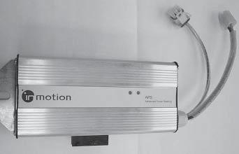
● Remove the panel and the display. Do not disconnect the plug connection. Only put the display down on the side to allow access to the steer module.
Procedure
● Switch the truck on.
● Close the seat switch (sit on the seat), activate the safety pedal and depress the accelerator until the drive wheel starts to turn slowly. Maintain this position and carry out the next step.
● Disconnect the speed detection 6 pole connector (A, Fig. MS-2140-019) while the drive wheel is turning slowly. The system should respond as follows:
-The mechanical brake decelerates the drive wheel.
-The drive module is cut out and the main contactor drops.
-The service display is illuminated.
-In LOG EVENTS, errorno. 180 “ECR3 HALL SENSOR” is stored.
● Switch the truck off.
● Re-connect the speed detection 6 pole connector (A, Fig. MS-2140-019).
● Switch the truck on. The truck should start up as normal with no error message displayed.
● Close the seat switch (sit on the seat), activate the safety pedal and depress the accelerator until the drive wheel starts to turn slowly. Maintain this position and carry out the next step.
● Disconnect the steering motor supply 4 pole connector (B, Fig. MS-2140-019) while the drive wheel is turning slowly. The system should respond as follows:
-The mechanical brake decelerates the drive wheel.
-The drive module is cut out and the main contactor drops.
-The service display is illuminated.
-In LOG EVENTS, error no. 102 “ERROR STEER MOTOR” is stored.
If the test is not successful, the steer module must be replaced before starting the truck again.
183 ESR4500 06/2004 • Printed in GermanyMANY MS-4.3-2140 ELECTRICS
A B
Drive Module Safety Test
DANGER
Danger to personnel in the vicinity!
A faulty safety circuit can cause the truck to start suddenly and accidentally. People standing in the way of the truck could be fatally injured.
Before carrying out the safety test jack the truck up so that the drive wheel is clear of the ground.Wedge the load wheels with blocks.
WARNING
Risk of scalding and injury to eyes.
The power fuse can burn, causing burning metal particles to explode.These particles can cause serious eye injuries and scald unprotected skin.
Always wear protective glasses and appropriate protective clothing. Only use encapsulated power fuses.With these fuses, the fuse strip is covered to prevent liquid metal particles from spraying.
Tools required
A self-assembled test unit. You will require:
2 off35mm² cross section power cable Part no. 812334-004
1 offFuse holder Part no. 802817
1 off200 A power fuse, encapsulated Part no. 802816-004
1 offInsulating plate, approx. 150 x 100 mm
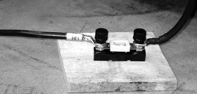
MS-2140-020
Fit the fuse holder onto the insulating plate. Fit each end of the power cable to the fuse holder.
To carry out the test you will then need 2 off M8 nuts. This attaches the test wiring to the motor terminals.
Preparatory measures
● Disconnect the battery.
● Press the horn for approx. 3 seconds. This will fully discharge the drive module capacitors.
● Jack up the truck (see Chapter 1 and safety instruction above).
● Fold up the seat and the panel.
Procedure
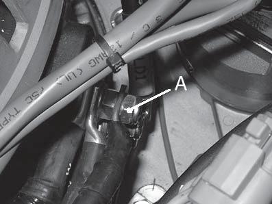
● Using an additional M8 nut (A, Abb. MS-2140021) attach one end of the test wiring to the U terminal of the traction motor. Do not loosen the motor cables themselves in the process.
● Attach the other end of the test wiring to the V terminal of the traction motor using an additional M8 nut. Do not loosen the motor cables themselves in the process.
● Guide the cables and the fuse holder out of the truck so that the folded down seat panel does not damage the cables when they are on the seat. Fold the seat back up and place the fuse holder on the ground.
● Connect the battery.
● Switch the truck on.
184 ESR4500 06/2004 • Printed in Germany MS-4.3-2140
ELECTRICS
MS-2140-021
● Close the seat switch (sit on the seat), apply the safety pedal and depress the accelerator as far as it will go.
● The system should respond immediately as follows:
-The main contactor drops (opens).
-The service display is illuminated.
-In LOG EVENTS, error no. 301 “SHORT CIRCUIT TM” is stored.
● Disconnect the battery again.
● Press the horn for approx. 3 seconds. This will fully discharge the drive module capacitors.
● Disconnect the test wiring from the V terminal of the traction motor and connect it to the W terminal with the additional M8 nut. Do not loosen the motor cables in the process.
● Guide the cables out of the truck so that the folded down seat panel does not damage the cables when they are on the seat. Fold the seat back.
● Connect the battery.
● Switch the truck on.
● Close the sea switch (sit on the seat), apply the safety pedal and depress the accelerator as far as it will go.
● The system should respond immediately as follows:
-The main contactor drops (opens).
-The service display is illuminated.
-In LOG EVENTS, error no. 301 “SHORT CIRCUIT TM” is stored.
If the test fails, replace the drive module.
Final procedure
● Switch the truck off.
● Disconnect the battery again.
● Press the horn for approx. 3 seconds. This will fully discharge the drive module capacitors.
● Remove the test wiring.
● Connect the battery.
● Switch the truck on.
● Test the operation. Close the seat switch (sit on the seat), apply the safety pedal and gently depress the accelerator (not all the way). The drive wheel turns slowly without error message.
● Switch the truck off.
● Jack down the truck.
185 ESR4500 06/2004 • Printed in GermanyMANY MS-4.3-2140 ELECTRICS
Blank page
186 Printed in Germany
187 Printed in Germany
BRAKE
Blank page
188 Printed in Germany
Load Wheel Brake
General
The load wheel brake is a self-adjusting drum brake. The brake is the same size for all truck models, irrespective of the capacity. There is no need for regular adjustment.
Brake Lining
Disassembly
DANGER
Risk of injury.
A non-supported or insufficiently supported truck or truck part can suddenly drop and cause serious injuries if you leave your hands or other body parts underneath it.
Always support a raised truck with wooden blocks or other appropriate equipment to relieve the jack.
● Switch the truck off. Disconnect the battery.
● Risk of tipping. It is essential to observe Chapter 1, Jacking up theTruck. Jack up a load arm until you can pull off the load wheel. The load wheel should be a maximum 10 mm clear of the ground. Support the load arm with hard wooden blocks to relieve the jack.
● Remove the wheel cap and the retaining ring from the steering knuckle.
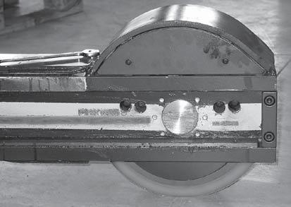
● Pull off the load wheel. If necessary, you can set the brake shoe back slightly. The reverse side of the brake contains 4 holes. Holes A (Fig. MS2140-063) provide access to the eccentrics. Twist these slightly to make it easier to pull off the load wheel. Holes B allow the brake lining thickness to be checked.
DANGER
Risk of injury from pre-tensioned springs.
Pre-tensioned springs can cause serious eye injuries.
Always wear a splint-proof protective glasses and suitable clothing to prevent injuries to your eyes and body.
● Remove springs C, E and F (Fig. MS-2140-064).
● Using a blunt, burr-free lever, lever one brake shoe towards the inside in order to press in the brake cylinder piston. Do not press directly on the piston. This could damage the brake piston sleeve.
● Remove the brake shoe from the brake piston groove.
● Remove the other brake shoe in the same way.
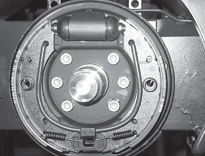
Assembly
● Clean all components. Remove oil and grease as required with a brake cleaning agent. MS-2140-064
189 ESR4500 06/2004 • Printed in Germany MS-5.0-2140 BRAKE
A B MS-2140-063
E F D
C
● Assemble the brake shoes in the reverse order of disassembly.
● Before installing the load wheel with the brake drum: Set the brake shoes using the eccentric to a distance of 199.4 +/- 0.2 mm. Otherwise you will not be able to push the load wheel over the brake shoes.
199,4 +/- 0,2 mm
● Fix the load wheel again.
MS-2140-064
● Now activate the brake pedal approx. 10 times. This will automatically adjust the brake.
Wheel Brake Cylinder
General
For safety reasons, wheel brakes cylinders are only available as complete assemblies. They are not designed to be repaired in the field.
Disassembly
Jack up and secure the truck. See previous section “Brake lining, disassembly”.
● Remove the brake shoes (see previous section).
● Push a flat tray underneath the jacked up load wheel to collect the brake fluid.
● Unscrew the brake line (B, Fig. M0945) from the wheel brake cylinder.
● Undo the two mounting studs (A) from the wheel brake cylinder.
● Remove the wheel brake cylinder.
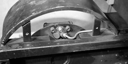
Assembly
● Remove the grease from all components using a brake cleaning agent.
● Insert the new wheel brake cylinder and screw it in tight.
● Re-connect the brake line.
● Re-install the brake shoes and the load wheel. However, do not yet apply the brake. The brake system must first be bled.
Bleeding the load wheel brake and replacing the brake fluid
DANGER
Danger of death!
The use of hydraulic oils or lubrication oil instead of the approved brake fluid will cause the brake to fail. Fatal accidents could result.
Only use brake fluid which complies with the specifications of the lubricant table (see Chapter 1).
Jack up and secure the truck. See previous section “Brake lining, disassembly”.
Bleeding is normally only required for the wheel brake cylinder that has been replaced. When replacing the brake fluid, open the vent screws (C, Fig. M0945) evenly on both wheel brake cylinders to fully remove the old brake fluid from the brake system (by pumping on the brake pedal). Then start to bleed the brake system as follows:
190 ESR4500 06/2004 • Printed in Germany MS-5.0-2140
BRAKE
M0945
A B C
➊ Remove the protective cap from the vent screw.
➋ Insert a transparent hose onto the vent screw, placing the free end in a clean container with some new, uncontaminated brake fluid. The hose end should dip into the brake fluid.
➌ Get an assistant to apply the brake pedal.
➍ While the brake pedal is depressed, open the vent screw half a turn.
➎ When the assistant reaches the stop with the brake pedal and the brake fluid still emerges mixed with air, get the assistant to keep pressing on the brake pedal and close the vent screw.
➏ With the vent screw closed, release the brake pedal in order to get brake fluid from the reservoir into the system.
➐ Check the brake fluid level in the main brake cylinder reservoir. Replenish if the brake fluid is below the max. level. This will prevent air from being suctioned.
● Repeat the steps 3 until 7 until the brake fluid emerges without any bubbles. Then close the vent screw.
191 ESR4500 06/2004 • Printed in Germany MS-5.0-2140 BRAKE
Operating Brake
Disassembly
CAUTION
Do not allow brake components to come into contact with oil or grease.
The item numbers in brackets refer to Figure MP-2140076.
● Disconnect the battery.
● Jack up the truck until the drive wheel is free, support the truck and prevent it from rolling away (see chapter 1).
● Undo the electrical connection (3) from the brake wiring.
● Undo the brake line (B) at the top of the magnetic body.
● Unscrew the three hex. socket screws (1).
● Remove the magnetic body (2) from the motor (including everything connected to it).
Test and Inspection
● Check the friction plate (6) and rotor (5) for even wear, deep grooves, cracks and signs of burning. Replace any worn or damaged components.
● Measure the thickness of the rotor (5). The wear limit is 9.5 mm. If the thickness of the rotor is the same as or less than this, replace the rotor.
Assembly
● Assemble the brake in the reverse order of disassembly.
CAUTION
It is essential to correctly reset the air gap after assembly.
Air gap setting
Befestigugs-Schrauben der Bremse am Fahrmotor (3 Stück)
The operating air gap is measured between the magnetic body and the armature plate when the truck is braked. The air gap must be set to 0.3 mm (see Fig. M1467).
● Unscrew the hollow screws (A) until they rest against the friction plate.
● Torque the hex. socket screws (1) evenly to 9.5 Nm.
● Check the operating air gap along several points using a feeler gauge. The air gap should be even all the way along.
● To increase the air gap unscrew the hollow screws (A) slightly. To reduce the air gap screw the hollow screws (A) into the magnetic body (1). Now, measure again as described above.
● When the air gap has been correctly set, torque the hex. socket screws (1) again to 9.5 Nm.
192 ESR4500 06/2004 • Printed in Germany MS-5.0-2140 BRAKE MS-5.0-1723
193 ESR4500 06/2004 • Printed in Germany MS-5.0-2140 BRAKE MS-5.0-1723 1 2 3 4 5 6
A Air gap B
MP-2140-076
Setting the brake pedal clearance
● Using a steel ruler, measure the brake pedal clearance. The clearance should be 3 +/- 1 mm.
● If necessary, adjust the clearance. Undo the counternut (A) and adjust the clearance using the adjusting screw (B).
194 ESR4500 06/2004 • Printed in Germany MS-5.0-2140
A B
BRAKE 3+/-1mm
MS-2140-065

195 Printed in Germany STEERING
page
196 Printed in Germany
Blank
Steering General
Functional Description
The steering system consists of the steer module (SDM), the nominal value transmitter (steering sensor ECR4), steering feedback sensor (ECR3) and the steer motor (M3).
A steering wheel revolution generates a steering command on the steer module input (SDM) via the nominal value transmitter (ECR4).
ECR4 is a stage motor used as a generator. This stage motor generates (induces) a voltage. The phase position of this voltage depends on the direction of turn, while the voltage depends on the speed of turn.
A voltage to power the steer motor, which is dependent on the input signal, is produced in the steer module. The
Whenever SFS 1SA is switched, the value calculated by the steer module is set to 0°. This corrects any deviation in the position calculation and allows a zero position to be defined via an error routine (e.g. after the drive wheel has been manually turned).
The sensors are activated by a cam on the gear unit cover (Fig. MS-2140-036). If the cam turns passed a sensor, the sensor switches. If a sensor has switched, an LED in
steer motor is a brushless DC motor (EC = Electrical Commutated).
The position of the steered wheel is monitored by the steering feedback sensor (ECR3) fitted in the steer motor. This encoder consists of three Hall sensors on a PCB. The steering feedback sensor calculates the position of the steered wheel to a tolerance level of +/- 0.5°.
This is a 4 quadrant steering system. An inductive proximity switch (SFS 2) recognises the quadrants. The second inductive proximity switch (SFS 1SA) recognises the 0° position of the drive wheel.
the sensor lights up (Fig. MS-2140-045). This allows the status of the sensor to be checked at a glance.
The grey areas in Fig. MS-2140-036 correspond to an angle of approx. +/-5°, with reference to 0°, 90° and-90°. The steer module (SDM) expects the sensors to switch in these sectors.
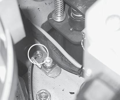
197 ESR4500 06/2004 • PRINTED IN GERMANY MS-6.0-2140
STEERING
SFS 1SA SFS 2 90° - 90° 0° I II III IV
SDM 3 M3 R S T DC Motor ECR 3 HALL C HALL A +5 V DC HALL B COMM Ain 1+ Ain 1+5 V out Ain 2+ Ain 2P5 P6 P4 P2 P1 P3 13 14 15 16 4 ECR 4 123456 1 2 3 4 CA204 1 2 3 4 123456 CA 413 CA 437 CA 412 CA 436 CA 414 3 4 1 6 2 5 1 2 3 4 5 6 MS-2140-037
Kamm LED
MS-2140-036
MS-2140-045
STEERING
Of the four available quadrants, the first and second are used. This produces a working angle of 180° for the steering.
The steering stops electrically at a steer angle of +/- 90°. An additional mechanical stop is applied to a steer angle of +/- 100°.
Quadrant - Definition
The quadrants are defined as follows:
I:1. Quadrant of90° to 0°
II:2. Quadrant of 0° to -90°
III:3. Quadrant of-90° to 180°
IV:4th quadrant of180° to 90°
Error routine INFORMATION
The steering system stores the steer angle at the time the truck is switched off.The next time the truck is powered up (during the self test), the steer module (SDM) compares the current position of the steered wheel with the stored value.
If the new position of the angle is not in the same quadrant as the stored angle, an error routine begins.
When the error routine starts …
● ... the travel speed is reduced to creep mode.
● ... the software stop of the steering system cuts out at +/- 90° and you can steer as far as the mechanical stop at +/- 100°.
● ... the max. permissible speed of the steer motor is restricted to 1500 rpm.
● ... the steer angle display is switched off.
● ... the steer fault display lights up.
● ... the message „STEERING SENSOR. TURN STEER WHEEL“ is shown on the message display.
Ending the error routine
To terminate the error routine and return to normal mode, the SFS 1SA sensor must be recognised once. Now set the accelerator pedal to neutral.
Causes of error routine activation
In most cases the cause will be manual turning of the steered wheel (wheel change, repairs carried out while truck is jacked up on the transmission). During the next self test during power up the following error message is entered in the service menu logbook.
Message:184Start error SDM
Cause:Wrong quadrant detected
The same error message can however be generated by a faulty sensor being identified as faulty during truck power up.
If a sensor fails while the truck is travelling, the following error messages may appear in the service menu log.
Message:182SFS 1 SW expected
Cause:SFS 1SA sensor does not switch.
Message:183SFS 2 SW expected
Cause:SFS 2 sensor does not switch.
Other error causes
With all other errors the steer module SDM interrupts the power supply to the brake (truck brakes) and travelling is disabled. An error message is displayed which will depend on the cause. See Electrics chapter, error messages.
198 ESR4500 06/2004 • Printed in Germany MS-6.0-2140
Examples of steer faults
Here are 2 examples to provide a better understanding of the causes of steer faults.
Example 1:
Manual wheel change, drive wheel turned 160° to the right
The steer module has stored an 80° angle as the position of the drive wheel when the truck was parked. The drive wheel is therefore in the 1st quadrant:
What is the result? The next time the truck starts up, the steer module compares the stored position (80°) with the current position (-80°) and detects an incorrect quadrant (2nd quadrant). The error routine starts.
Ending the error routine
The error routine can only be ended if SFS 1SA has been switched once.
You have the choice of 2 directions for steering and normally you do not know the actual position of the drive wheel.
Let’s assume you want to steer right first of all. What happens?
20° later, the drive wheel reaches the mechanical stop at 100° (see Fig.MS-2140-040). The error routine does not end as you have not reached the switch area of the proximity switch SFS 1 SA.
Let’s suppose you now change the drive wheel. You manually turn the drive wheel 160° to the right in order to access the wheel bolts.
In this situation you can therefore only end the error routine by steering to the left in order to reach the switch area of the proximity switch SFS 1SA.
What happens if you steer left?
You reach the switch area of proximity switch SFS 1SA. The proximity switch is applied. This switch signal resets the stored and calculated values in the drive module to 0°.
If you now release the accelerator pedal, the error routine ends and the truck returns to normal travel mode.
199 ESR4500 06/2004 • PRINTED IN GERMANY MS-6.0-2140 STEERING
SFS 1SA SFS 2 90° - 90° 0° I II MS-2140-038 SFS 1SA SFS
90°
90° 0° I II
2
-
MS-2140-039
90°
90° 0° I II
SFS 1SA SFS 2
-
MS-2140-040
STEERING
Example 2: Manual wheel change, drive wheel turned 70° to the right
The steer module has stored an 80° angle as the position of the drive wheel when the truck was parked. The drive wheel is therefore in the 1st quadrant.
What happens if you steer left?
Starting from the 80° position as the stored value, after a further 10° you reach the software stop at 90°. The steering stops. The steering angle display shows a steer angle of 90°.
MS-2140-041
Let’s suppose you now change the drive wheel. You manually turn the drive wheel 70° to the right.
What is the result? The next time the truck starts up the steer module compares the stored position (80°) with the current position (10°). As the drive wheel is still in the 1st quadrant, the error routine does not start. Steering remains in normal mode.
MS-2140-043
However, the steer angle on the drive wheel is actually only 20° with respect to 0° for normal forward travel. The error routine does not start, as the drive wheel is still within the 1st quadrant.
INFORMATION
When the truck is started, provided the last stored value and the current calculated value for the drive wheel position are in the same quadrant, the error routine will not start.
You will only recognise this error by the fact that the steering wheel display does not match the actual steer angle on the drive wheel. In addition,you will not reach the full steering range of 90° to -90°.
What happens if you steer right?
Starting from 80° as the stored value, after a further 10° you reach the switch area of the proximity switch SFS 1SA. The proximity switch applies. This switch signal resets the stored and calculated values in the drive module to 0°. The steering angle display now matches the actual position of the drive wheel. The full steering range of 90° to -90° is now available again.
200 ESR4500 06/2004 • Printed in Germany MS-6.0-2140
SFS 1SA SFS 2 90° - 90° 0° I II
1SA SFS 2 90° - 90° 0° I II
1SA
2 90° - 90° 0° I II
SFS
MS-2140-042 SFS
SFS
There is no message displayed when the calculated and stored angles are reset, as the steer module is not undergoing the error routine. This happens in normal mode of the steer module every time the cam on the gear unit cover goes into the switch area of the proximity switch SFS 1SA.
To rectify this error, you just need to steer accordingly so that the cam on the gear unit cover goes into the switch area of proximity switch FFS 1 SA.
201 ESR4500 06/2004 • PRINTED IN GERMANY MS-6.0-2140 STEERING
2 90° - 90° 0° I II
SFS
1SA SFS
MS-2140-044
STEERING
Setting the SFS … proximity switches

MS-2140-046
The proximity switches must be set to a length of 46 +/0.5 mm, measured from the bottom of the mount bracket to the top of the proximity switch.
● Switch off the truck and prevent it from being switched on again (disconnect the battery).
● Open the motor compartment cover.
● Disconnect the seat switch connector and remove the seat together with the motor compartment cover.
● Remove connectors PC-436 and PC-437 from the connector console.
● Remove the 3 mounting screws (14) from the steer motor (13).
● Pull the steer motor out from the top.
● In a vice, tension the steer motor around the drive pinion (15) to prevent the motor shaft from twisting (use protective vice chops and only tighten the vice gently).
● Remove the mounting screw (18) from the drive pinion and the washer (17).
● Take the steer motor out of the vice and tighten it around the housing.
● Using a suitable extractor pull out the drive pinion.
Assembly
CAUTION
Risk of damage to the feather key and the drive pinion.
Metal hammers will damage the feather key and the drive pinion.
MS-2140-047
If the length exceeds 46.5mm, the proximity switch may be damaged by the cam passing by it.
If the setting is less than 45.5mm, the proximity switch will either not identify the metal surface of the cam at all, or else switch intermittently and unreliably.
Replacing the steer motor
Disassembly
All item numbers refer to figure MP-2140-007.
Only use a plastic hammer.
Apply a thin layer of type M grease to the drive shaft, the pinion and the contact surface (front side) of the steer motor (see lubricant table Chapter 1).
Assemble the steer motor in the reverse order of disassembly.
202 ESR4500 06/2004 • Printed in Germany MS-6.0-2140
203 ESR4500 06/2004 • PRINTED IN GERMANY MS-6.0-2140 STEERING 4 3 2 14 5 21 20 19 23 15 23 19 22 20 8 7 24 1 9 16 17 18 12 11 6 10 13 25 26 MP-2140-077
STEERING
Steering wheel
Disassembly
There is an opening on the right hand side of the steering wheel panel. Turn the steering wheel until the hex. socket screw (5, Fig. MP-2140-064) can be reached through the opening. Undo the screw and pull off the steering wheel.

MS-2140-055
Assembly
Put the steering wheel onto the shaft. Refit screw 5 and tighten it securely.
204 ESR4500 06/2004 • Printed in Germany MS-6.0-2140
205 ESR4500 06/2004 • PRINTED IN GERMANY MS-6.0-2140 STEERING 1 2 3 4 7 6 8 5 16 15 14 10 11 13 12 17 8 9 18 19
MP-2140-064
STEERING
Steering Sensor (ECR4)
Disassembly
● Remove the steering column cover (9, Fig. MP2140-064 on previous page).
● Remove connector PC414.
● Remove the screws (25) and take off the steering sensor (26).
● Remove the retaining plate from the steering sensor. To do this, remove the screws (23) and nuts (27).
INFORMATION
The steering sensor cannot be serviced. If faulty, replace with a new one.
Assembly
● Attach the retaining plate to the new steer sensor.
● Assemble the steering sensor back into the steering column in the reverse order of disassembly.
● Calibrate the new steering sensor (see service menu in Chapter 4).
206 ESR4500 06/2004 • Printed in Germany MS-6.0-2140
207 ESR4500 06/2004 • PRINTED IN GERMANY MS-6.0-2140 STEERING 1 2 2 3 4 11 5 10 9 8 7 6 17 18 19 20 15 14 13 12 32 30 31 29 28 28 16 21 22 23 24 25 26 27
208 Printed in Germany
Blank page
209 Printed in Germany
MAST
210 Printed in Germany
Blank page
Mast
DANGER
Risk of trapping and severing limbs! When carrying out work on the mast and the attachments: always block the mast stages and attachments to prevent them from accidentally moving. Make sure the wooden blocks and lifting gear used have sufficient capacity.
General
Torque Requirements
All screw connections on the mast must be torqued to the standard values. See Chapter 1 for these values.
Lifting Gear Minimum Capacity
Note the minimum capacity for the lifting gear whenever carrying out work on the mast.
211 ESR4500 06/2004 • Printed in Germany MS-7.0-2140 MAST Rev. 01/03
acityap C mimuMin Gear giftinL Mast theig H iftL * earg gliftin rfo acitycap Min to 2.0 mm 4,592 to mm ,140 4g k 1,000 to 0 2 mm 7,200 to mm ,490 5g k 1,500 to 2.0 mm 11,435 to mm ,120 8g k 2,000 to 6 1 / 4 1 mm 6,090 to mm ,440 4g k 1,000 to 1.6 / 1.4 mm 9,900 to mm ,690 6g k 1,500 to 6 1 / 4 1 mm 0,230 1g k 2,000 rksfo dan ardug adlo gindexclu * ecarriag rkoF sedu earg gliftin rfo acitycap Min l l A kg 150
M01-GB
Mast Testing (Assembled)
Clean the mast channels and test the tracking paths of the rollers in the mast channels. There should only be wear in the rear section of the I beam where the rollers slide. There should not be any grooving or cutting in the I beam caused by the mast rollers. If grooving or cutting is evident, it will normally take place at the side of the roller; 10 mm from the channel face. In this case the mast rollers will have to be adjusted. Remove a shim from underneath the affected mast roller.
A recheck of the mast channel will be required. De-grease the running area of the roller in the mast channel and spray on a thin layer of paint. Extend and retract the mast, and then check the tracking path of the roller (the paint will show up the tracking path).
If the contact pattern matches requirements, apply grease to the contact surfaces (see lubrication table, chapter 1).
When the mast is raised and nearly fully extended, it should not tilt to the right or left but should be even and straight. All mast stages should be aligned. If a tilting condition exists, it is a sign that the shimming is too loose or unbalanced and will need to be adjusted.
All hose guide pulleys should move freely, check hoses for chafing.
Flaking
It is not uncommon for a new mast to appear as if it is flaking or peeling. This appearance indicates that the rollers are seating on the mast channel and this is considered normal. Eventually, this condition will disappear. The grease applied to the channel will retain these particles.
Mast Shock Absorbers
For maintenance and repairs of shock absorbers see the “Fork Carriage” section.
Mast end stops
The mast end stops are so-called “Polystop blocks”. They must be checked regularly for wear.
Fork Adjustment
With the forks fully lowered and level, adjust so that the top of the fork tip is a maximum of 65 mm off the floor.
The maximum fork height (raised) is to be within +/– 25 mm of the fork height specified on the truck data plate.
212 ESR4500 06/2004 • Printed in Germany MS-7.0-2140
MAST
Mast Removal and Assembly
General
DANGER
All assembly work on the mast is hazardous.
Unsecured stage masts and attachments can sever limbs or even cause fatal injuries. Always block and secure the respective components properly prior to starting assembly.
Pressurised hydraulic systems can cause serious injury when the system is opened.
High pressure hydraulic oil can cause serious injuries.
Whenever a high pressure fluid enters the skin it must be treated as an emergency, even if the skin initially shows no reaction.
Physical effects may take time to set in.
Secure all connections before re-applying system pressure. Keep hands and body away from any ports as high pressure hydraulic oil can emerge.
Use absorbent paper to trace leaks, never use your hands!
It is necessary to remove the mast in order to replace the mast rollers, to remove the fork carriage and to transport the truck.
Disassembly
All item numbers in brackets refer to diagram MP2140-055 on the following page.
● Extend the mast fully.
● Remove the forks or the attachment.
● Remove the load backrest.
● Attach a load sling around the top cross member of the 1st and 2nd mast stages (2,3).
● Reduce the system hydraulic pressure: Open the filler neck lid on the hydraulic reservoir.
DANGER
Risk of trapping and severing limbs!
Falling assemblies can sever limbs and cause fatal injuries.
Note the minimum capacity for the lifting gear required. Additionally secure raised mast stages with square wooden blocks to prevent them from accidentally lowering.
● Place a flat tray underneath the mast area and collect any spilled hydraulic oil.
● Now raise the 1st and 2nd mast stages (2, 3) until the main hydraulic line on the distributor and the mast mounting screws (27) are accessible.
● Secure the work area: Place square wooden blocks in the tracks of the outer mast and lower the 1st and 2nd mast stages onto them.
● Unscrew the main hydraulic line from the distributor block located at the bottom of the mast. Seal both ends with filler plugs.
● Loosen the mast mounting screws (27) from the reach carriage. Do not yet remove the screws!
● Remove the wooden blocks and lower the 1st and 2nd mast stages.
● Remove the load sling from the 1st and 2nd mast stages and attach it to the highest cross members of the outer mast (1), of the 1st and 2nd mast stages. Take care not to damage the height encoder wiring in the process.
● Tension the mast with the crane.
213 ESR4500 06/2004 • Printed in Germany MS-7.0-2140 MAST
214 ESR4500 06/2004 • Printed in Germany MS-7.0-2140 MAST 1 2 3 4 5 4 5 6 7 8 7 7 31 27 28 29 30 16 17 9 10 11 12 13 14 9 10 11 12 13 14 15 21 22 18 19 24 23 20 26 25 2nd mast stage 1st mast stage Outer mast
MP-2140-055
● Now remove the 8 mast mounting screws from the reach carriage and the screws (27) at the bottom of the mast.
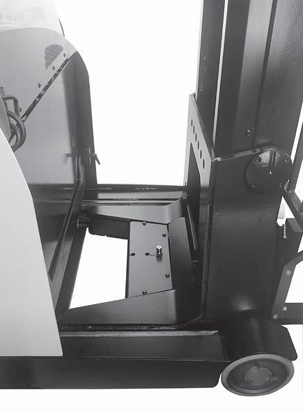
● Remove the cover (A, Fig. MS-2140-001).
● Remove the covers (6, 8 and for 2.0 tonne mast also 31) of the lift cylinders on the left and right hand sides of the outer mast.
● Mark the hydraulic hose connections (Fig. MS2140-010) for the auxiliary function on the left channel of the 1st mast stage for later re-assembly.
● There is a danger of mixing up the screws.
● Disconnect the hydraulic hose connection for the auxiliary function. Apply filler plugs to all open ports.
● Remove the connector and where necessary the wire attachments of all the electrical connections from the reach carriage to the mast. Pull out and upwards all the wires from the reach carriage to the mast. Temporarily attach the loose wires to the mast.
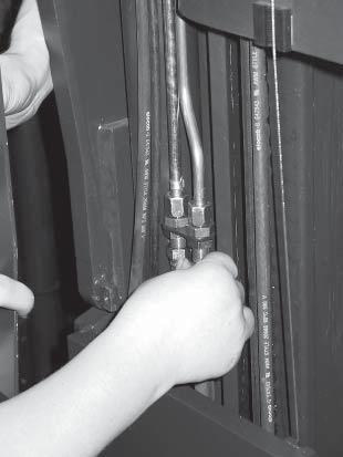
● Secure the fork carriage with a load sling to prevent it from moving in the mast.
● Raise the mast up out of the reach carriage.
● Place the mast with its back (the side facing the driver) onto a suitable surface with sufficient capacity (pallets, steel benches).
Assembly
Assembly is the reverse of disassembly.
After assembling, check or adjust as follows:
● Bleed the lift cylinders and free-lift cylinder
● Test the hydraulic system
● Check / adjust the chain tension
● Check / calibrate the height encoder
● Check / calibrate the load sensor
215 ESR4500 06/2004 • Printed in Germany MS-7.0-2140 MAST
A
MS-2140-001
MS-2140-010
Dismantling and Assembling the Mast
General
When dismantling switches and lines (electrical, hydraulic), the mast attachments (base plates, clamps) must always be undone.
This facilitates positioning for later re-assembly and normally saves having to adjust the switches.
For lift chains it is preferably to loosen the chain bolt, not the chain anchor. Here too you can avoid most of any subsequent adjustment work.
Dismantling
Fork Carriage Removal
● Remove the mast (see previous section) and place it down horizontally.
● Remove the free lift switch (FLS), otherwise it will be damaged when the fork carriage is extended.
● Remove the shock absorbers and the free lift chain.
● Undo and remove all the hydraulic lines and if applicable the electrical connections to the fork carriage.
● Attach a load sling around the fork carriage.
● Using the crane, move the fork carriage “down” from the 2nd mast stage.
2nd Mast Stage Removal
● Remove all mast cables, hydraulic hoses and lines and if applicable the height encoder and the camera system including all wiring and ropes, up to the outer mast. The wires and hoses should not run into the inner area of the mast stages. This would damage them when the mast is dismantled further.
● Remove the free lift chain and the pulley from the free lift cylinder. Store the chain so that it is protected from contamination.
● Remove the lift chains. Store the chains so that they are protected from contamination. Mark the position of the chains (left / right) in order to be able to re-fit them in their original sides.
● Using a crowbar, push the 2nd mast stage down until the bottom mast rollers are accessible.
● Remove the bottom mast rollers and shims of the 2nd mast stage. Place the rollers and shims in such a way that they can later be easily fitted back at the same place.
● Attach 2 load slings (one for the lower and one for the upper section of the 2nd mast stage).
● Guide the 2nd mast stage (without rollers!) out of the 1st mast stage, using a crane. Place the second mast stage on a suitable surface.
1st Mast Stage Removal
● Remove the guide pulleys for the hoses and chains at the top left and right of the 1st mast stage.
● Remove the covers (2, 6) and the brackets (4, 7) from the outer mast (see Fig. MP-2140-086 on the following page).
● Remove the screws (18 and 16, Fig. MP-2140055) and the locking screws (17) from the lift cylinders.
● Using a crowbar, push the 1st mast stage up until the mast stage can be attached to the crane with 2 load slings. The ends of the lift cylinder piston rods should no longer be in the mast stage seats, and should be free.
● Using the crane, pull the 1st mast stage out until the mast stops become visible through the circular hole at the bottom.
● Undo the mounting screws (9, Fig. MP-2140-055) from the mast stops and remove the mast stops from the channel.
216 ESR4500 06/2004 • Printed in Germany MS-7.0-2140
MAST
217 ESR4500 06/2004 • Printed in Germany MS-7.0-2140 MAST 19 21 20 22 3 4 15 18 17 14 13 10 11 9 8 3 12 16 7 6 5 1 2
MP-2140-086
● Using a crowbar push the 1st mast stage in the outer mast down until you can remove the top and bottom mast rollers.
● Now using the crane pull the 1st mast stage completely out of the outer mast. Place the mast stage on a suitable surface.
Replacing the Mast Rollers
General
You will need the special tool (P/N 810705) to calculate the required roller diameter. The mast roller bearing journals are slightly angled. Calculating the diameter by manually pulling the roller through the channel will produce an incorrect result.
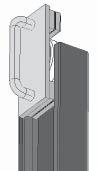
The mast rollers are replaced in 2 main stages:
● Calculating the required roller diameter to prevent jamming or excessive play above the running area of the roller in the mast channel.
● Calculating the number of shims required to prevent lateral jamming or tipping between the left and right-hand mast channels.
Remove the mast and dismantle it as described in the previous sections. Clean the mast channels and remove all mast rollers and the shims.
Mast Roller Assembly
Calculating the Roller Diameter
You have a choice of 3 roller diameters:
Code B, 101,47 mm, Part No. 807334-002
Code C, 102,14 mm, Part No. 807334-003
Code D, 102,45 mm, Part No. 807334-004
● Always start with roller Code D. Fit the roller onto the tool (Fig. MS-2140-011).
INFORMATION
Rollers do not run in 500 mm areas (see Fig. MS-2140-012)! Only apply the tool outside these areas in order to calculate the required roller diameter. For fork carriages with 6 rollers, always select the mean roller diameter to be one grade lower than calculated.This will avoid jamming when the rollers enter the mast channel.
● Using the tool, pull the roller through the corresponding mast channel (see Fig. MS-2140-012). The roller should not jam at any point, nor should it even become stiff. In this case repeat the process with the next smallest roller until the roller easily rolls along the full running area of the mast channel. Put the roller down so that it can easily be identified at a later stage. Repeat these steps for all the mast rollers and the fork carriage rollers in their respective mast channels.
Calculating the Required Number of Shims
There are shim sizes available:
1.6 mm thicknessPart No. 060030-057
0.7 mm thicknessPart no. 060030-85
0.4 mm thicknessPart no. 795534
Outer Mast / 1st Mast Stage
● Fit both rollers (without shims) at the top of the outer mast.
● Position the 1st mast stage in the outer mast.
218 ESR4500 06/2004 • Printed in Germany MS-7.0-2140 MAST
MS-2140-011
Outer mast 1st mast stage 2nd mast stage
Lower mast rollers of 1st mast stage and corresponding running area
Upper mast rollers of outer mast and corresponding running area
Upper mast rollers of 1st mast stage and corresponding running area
Lower mast rollers of 2nd mast stage and corresponding running area
Running area of all mast rollers of the fork carriage
219 ESR4500 06/2004 • Printed in Germany MS-7.0-2140 MAST 500 mm 500 mm 500 mm 500 mm 500 mm 500 mm 500 mm 500 mm
MS-2140-012
● Using a crowbar push the 1st mast stage in the outer mast down until you can fit the top and bottom rollers (without shims) of the 1st mast stage. Fit the rollers and push the 1st mast stage back into the outer mast (same position as for retracted mast).
● Prepare a pile of shims, each consisting of a 1.4 mm, 0.7 mm and 0.4 mm shim.
● In the area of the upper mast rollers, press the 1st mast stage with a crowbar until the opposite mast rollers come into contact with the channel of the outer mast.
● Take the prepared stack of shims. Try to push the pile into the gap between the outside of the roller and the mast channel. It should be possible to push the shims without them becoming stiff or jamming.
● If required, increase or decrease the number of shims. Try to use as few shims as possible. Therefore try first with a thick shim before using thinner ones. Often you can use a thick shim instead of several thin ones.
● When you have calculated the required number of shims, distribute them evenly on either side.
● Now calculate the number of shims required for the bottom mast rollers. Distribute these evenly on either side as well.
● Remove the 1st mast stage from the outer mast.
INFORMATION
In the next stage do not distribute the shims crosswise, see Figs. M0381 and Abb. M0382.
● Place the previously calculated shims under their corresponding mast rollers.
● Push the 1st mast stage back into the outer mast.
● Pull the 1st mast stage with the crane as far up as possible into the outer mast until you can re-fit the mast stoppers.
● Fit the mast stoppers.
● With the 1st mast stage at the stop, check again the clearance of the mast rollers.
● Push the 1st mast stage back fully into the outer mast.
● Re-fit both lift cylinders.
● Re-fit the guide pulleys for the lift chains and hoses. Assemble the hoses and the rollers. It will not be possible to assemble the hoses at a later stage for reasons of space.
1st Mast Stage / 2nd Mast Stage
● Lift the second mast stage into the first stage.
● Using a crowbar push the 2nd mast stage down in the first mast stage until you can fit the top and bottom rollers (without shims). Fit the rollers and push the 2nd mast stage back into the 1st mast stage (same position as for retracted mast).
● Prepare a pile of shims, each consisting of a 1.4 mm, 0.7 mm and 0.4 mm shim.
● In the area of the upper mast rollers of the 1st stage, press the 2nd mast stage with a crowbar until the opposite mast rollers rest in the channel of the 1st mast stage.
● Take the prepared stack of shims. Try to push the pile into the gap between the outside of the roller and the mast channel. It should be possible to push the shims without them becoming stiff or jamming.
● If required, increase or decrease the number of shims. Try to use as few shims as possible. Therefore try first with a thick shim before using thinner ones. Often you can use a thick shim instead of several thin ones.
● Using a crowbar press against the upper mast rollers of the 1st mast stage until the opposite mast rollers come into contact with the channel of the outer mast. Try to push one of the thinnest shims into the gap between the outside of the roller and the mast channel. It should not be possible to push the shim in, but there should be a small amount of clearance.
220 ESR4500 06/2004 • Printed in Germany MS-7.0-2140 MAST
The numbers in brackets indicate the number of shims placed underneath.
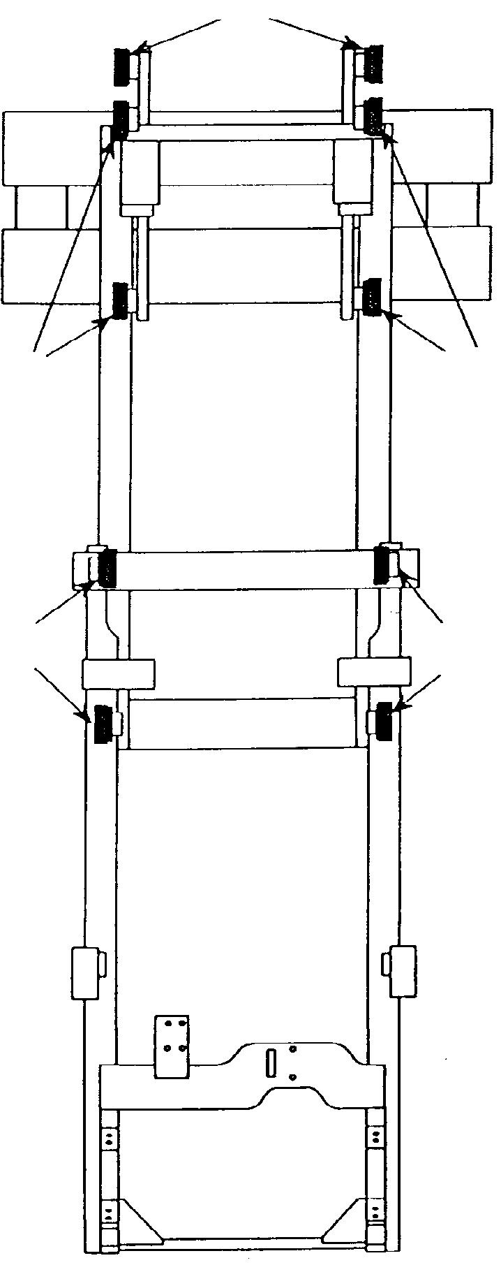
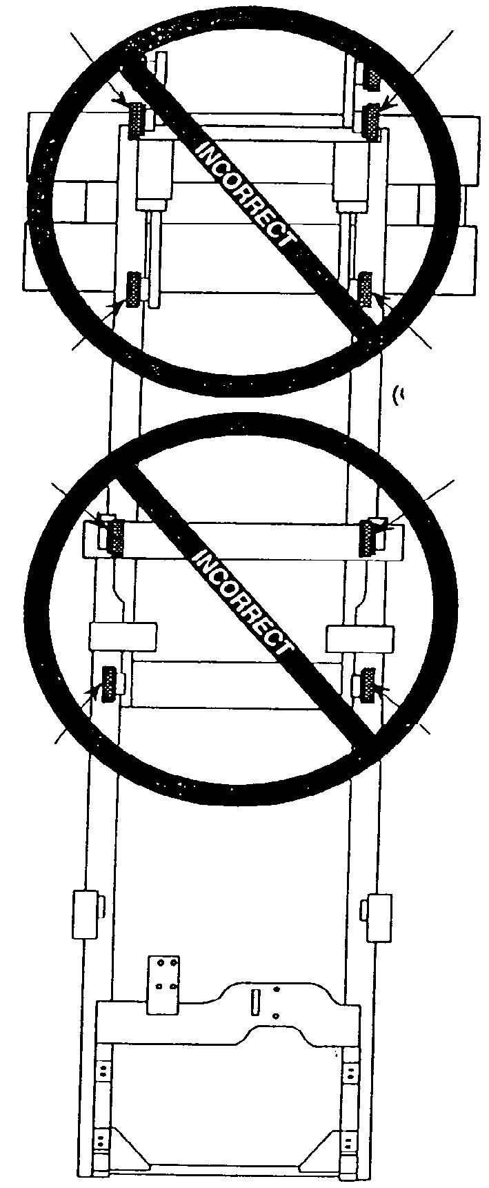
221 ESR4500 06/2004 • Printed in Germany MS-7.0-2140 MAST
M0381
(1) (2) (1)
M0382
(2) (2) (1) (1) (2) (1) (2) (2) (1)
● When you have calculated the required number of shims, distribute them evenly on either side.
● Now calculate the number of shims required for the bottom mast rollers. Distribute these evenly on either side as well.
INFORMATION
In the next stage do not distribute the shims crosswise, see Figs. M0381 and Abb. M0382.
● Push the 2nd mast stage down so that you can remove the rollers and insert the shims.
● Push the 2nd mast stage back into the neutral position.
● With the exception of the free lift switch, re-fit all the previously disassembled components which are not directly connected to the fork carriage.
Fork Carriage INFORMATION
Fork carriages for 2000 kg lift masts have 6 rollers. Fork carriages for lesser capacities have 4 rollers.
● Fit all rollers (without shims) to the fork carriage. For fork carriages with 6 rollers, always select the mean roller diameter to be one grade lower than calculated. This will avoid jamming when the rollers enter the mast channel.
● Guide the fork carriage into the 2nd mast stage from below.
● Push the fork carriage right up until the top rollers are at the end of the mast channel.
● Prepare a pile of shims, each consisting of a 1.4 mm, 0.7 mm and 0.4 mm shim.
● Using a crowbar press against the upper mast rollers of the fork carriage until the opposite mast rollers come into contact with the channel.
● Take the prepared stack of shims. Try to push the pile into the gap between the outside of the roller and the mast channel. It should be possible to push the shims without them becoming stiff or jamming.
● If required, increase or decrease the number of shims. Try to use as few shims as possible. Therefore try first with a thick shim before using
thinner ones. Often you can use a thick shim instead of several thin ones.
● For fork carriages with 6 rollers, push the fork carriage further up until the middle roller are at the end of the mast channel.
● Prepare a pile of shims, each consisting of a 1.4 mm, 0.7 mm and 0.4 mm shim.
● Using a crowbar press against the middle mast rollers of the fork carriage until the opposite mast rollers come into contact with the channel.
● Take the prepared stack of shims. Try to push the pile into the gap between the outside of the roller and the mast channel. It should be possible to push the shims without them becoming stiff or jamming.
● If required, increase or decrease the number of shims. Try to use as few shims as possible. Therefore try first with a thick shim before using thinner ones. Often you can use a thick shim instead of several thin ones.
● When you have calculated the required number of shims, distribute them evenly on either side.
● Pull the fork carriage back out of the 2nd mast stage.
● The lower rollers on the fork carriage are not accessible in the highest mast position. To calculate the number of shims required, proceed as follows:
Initially, use the same number of shims on the lower fork carriage rollers as for the upper (for 4 rollers) or middle (for 6 rollers) rollers.
INFORMATION
In the next stage do not distribute the shims crosswise, see Figs. M0381 and M0382.
● Fit the shims under the fork carriage rollers.
● Raise the fork carriage back into the 2nd mast stage.
● Manually push the fork carriage back up as far as the stop. The fork carriage should not jam.
● Now check the clearance of the lower fork carriage rollers in the 2nd mast stage: Using a crowbar press against the lower mast rollers of the fork carriage until the opposite mast rollers come into contact with the channel. The
222 ESR4500 06/2004 • Printed in Germany MS-7.0-2140
MAST
clearance should not be greater than that of the middle or upper rollers. To compare, you can move the fork carriage and check the top and bottom clearance alternately. If the clearance is greater on the bottom rollers, pull the fork carriage out of the 2nd mast stage until the bottom rollers are accessible. Insert a thin shim (0.4 mm) underneath. Manually push the fork carriage back up as far as the stops. Check the clearance again. If necessary, place another thin shim underneath. Important: It should be possible to push the fork carriage manually to the top end without jamming.
Final Work and Settings
● Re-fit all components that have been removed.
● Re-fit the mast in the reach mechanism.
● Bleed the hydraulic system.
● Check the mast stoppers. When the mast is fully extended it should not tilt to the side. The left and right stops on the mast stages should strike the stoppers at the same time. If necessary, fit shims. Note the position in which the plastic block is installed. The plastic must face the mast stop (see spare parts manual for details).
● If the height encoder and load monitor are present, they must be re-calibrated (see Chapter 4).
● Adjust the lift cylinders so that there is no clearance.
● Check the fork height setting and the lift chain tension.
223 ESR4500 06/2004 • Printed in Germany MS-7.0-2140 MAST
Free lift cylinder removal / installation with mast attached
DANGER
Risk of trapping and severing limbs! When carrying out work on the mast and the attachments: always block the mast stages and attachments to prevent them from accidentally moving. Make sure the wooden blocks and lifting gear used have sufficient capacity.
General
Torque Requirements
All screw connections on the mast must be torqued to the standard values. See Chapter 1 for these values.
Lifting Gear Minimum Capacity
DANGER
Risk of trapping and severing limbs!
Falling assemblies can sever limbs and cause fatal injuries.
Note the minimum capacity for the lifting gear required.
Additionally secure raised mast stages with square wooden blocks to prevent them from accidentally lowering.
Refer to the start of this chapter for the minimum capacity required for the lifting gear used.
Disassembly
DANGER
Pressurised hydraulic systems can cause serious injury when the system is opened.
High pressure hydraulic oil can cause serious injuries.
Whenever a high pressure fluid enters the skin it must be treated as an emergency, even if the skin initially shows no reaction.
Physical effects may take time to set in.
Secure all connections before re-applying system pressure. Keep hands and body away from any ports as high pressure hydraulic oil can emerge.
Use absorbent paper to trace leaks, never use your hands!
● Raise the fork carriage until the shock absorbers and the FLS switch are accessible.
● Secure the fork carriage: Attach a load sling around the fork carriage and hold it with the crane.
● Remove the shock absorbers and the free lift switch (FLS), otherwise it will be damaged when the fork carriage is extended.
● Place a flat tray underneath the mast area and collect any spilled hydraulic oil.
● Remove the protective cover for the hoses / cables and the free lift chain from the top of the free lift cylinder.
● Depressurise the lift circuit (activate lowering for at least 5 seconds)
● Undo and remove all the hydraulic lines and electrical connections to the fork carriage. Seal open hydraulic ports with filler plugs.
● Remove the free lift chain mounting studs.
224 ESR4500 06/2004 • Printed in Germany MS-7.0-2140 MAST Rev. 01/03
● Undo the bottom stud at the base of the free lift cylinder.
● Using the crane lower the fork carriage down onto a pallet positioned underneath it.
● Place a load sling around the highest cross member of the second mast stage.
● With the crane slowly raise the 2nd mast stage until the fork carriage rests freely on the pallet.
● Using a forklift, remove the fork carriage from the work area.
● Place the second mast stage onto wooden blocks placed underneath it.
● Remove the pressure line below the free lift cylinder. Fully remove the two steel hydraulic lines attached to the free lift cylinder. Seal the ports with filler plugs.
● Place a load sling below the middle attachment plate around the free lift cylinder. Gently tension the load sling with the crane. This will prevent the cylinder from falling out when you undo the final two mounting studs.
● Undo the two mounting studs (24) from the free lift cylinder.
● Using the crane, lift the cylinder out and put down on one side.
Assembly
Assembly is the reverse of disassembly.
Before bleeding, replenish with hydraulic oil up to the max. marking. After assembling, bleed the hydraulic system and check the operation of the FLS free lift switch.
225 ESR4500 06/2004 • Printed in Germany MS-7.0-2140 MAST
226 ESR4500 06/2004 • Printed in Germany MS-7.0-2140 MAST 1 2 3 4 5 4 5 6 7 8 7 7 31 27 28 29 30 16 17 9 10 11 12 13 14 9 10 11 12 13 14 15 21 22 18 19 24 23 20 26 25 2nd mast stage 1st mast stage Outer mast
MP-2140-055
227 ESR4500 06/2004 • Printed in Germany MS-7.0-2140 MAST 1 2 3 4 5 4 5 6 7 8 7 7 31 27 28 29 30 16 17 9 10 11 12 13 14 9 10 11 12 13 14 15 21 22 18 19 24 23 20 26 25 2nd mast stage 1st mast stage Outer mast
MP-2140-055
Lift cylinder removal / assembly
DANGER
Risk of trapping and severing limbs!
When carrying out work on the mast and the attachments: always block the mast stages and attachments to prevent them from accidentally moving.
Make sure the wooden blocks and lifting gear used have sufficient capacity.
General
You only need to remove the cylinders when carrying out repairs.
Lifting Gear Minimum Capacity
DANGER
Risk of trapping and severing limbs!
Falling assemblies can sever limbs and cause fatal injuries.
Note the minimum capacity for the lifting gear required.
Additionally secure raised mast stages with square wooden blocks to prevent them from accidentally lowering.
Refer to the start of this chapter for the minimum capacity required for the lifting gear used.
Disassembly
DANGER
Pressurised hydraulic systems can cause serious injury when the system is opened.
High pressure hydraulic oil can cause serious injuries.
Whenever a high pressure fluid enters the skin it must be treated as an emergency, even if the skin initially shows no reaction.
Physical effects may take time to set in.
Secure all connections before re-applying system pressure. Keep hands and body away from any ports as high pressure hydraulic oil can emerge.
Use absorbent paper to trace leaks, never use your hands!
● Fully lower the fork carriage.
● Place a flat tray underneath the work area and collect any spilled hydraulic oil.
● Remove the cylinder panels (6,8, 31 Fig. MP2140-055) and the top panels (2, 6 Fig. MP-2140086 on following page) with the brackets (4,7).
● Raise the fork carriage. Now lower the fork carriage onto approx. 20 cm long hard wooden blocks placed in the channels of the outer mast. Now lower the fork carriage further onto approx. 35-40 cm long hard wooden blocks placed in the channels of the 1st mast stage. This will prevent the mast from accidentally lowering.
● Now lower the fork carriage completely, the lift chains are now discharged.
● Remove the cylinder attachments (16, 17 and 18, Fig. MP-2140-055). Remove the chain bolts from the top of the cylinder tube connection. Secure the lift chains with wire to prevent them from falling down.
228 ESR4500 06/2004 • Printed in Germany MS-7.0-2140 MAST
229 ESR4500 06/2004 • Printed in Germany MS-7.0-2140 MAST 19 21 20 22 3 4 15 18 17 14 13 10 11 9 8 3 12 16 7 6 5 1 2
MP-2140-086
● Now depressurise the lift circuit (open the emergency lowering valve on the valve block)
● Manually pull the piston rod down out of the top seat. Do not use any tools. Tools will damage the piston rod.
● Press the piston rod into the lift cylinder as far as the stop.
● Place a load sling below the tappets of the cylinder tube and gently tension the cylinder with the crane.
● Undo the hydraulic connection to the lift cylinder (seal open hydraulic ports with filler plugs).
● Raise the lift cylinder out of the mast.
Assembly
Assembly is the reverse of disassembly. Note also:
DANGER
Risk of trapping and severing limbs!
You can injure your hands when inserting the piston rod into the top seat on the mast.
Never guide the piston rod with your hands, always hold the cylinder by the cylinder tube.
● To insert the piston rod in the top seat you will need an assistant to activate lifting (ideally a forklift driver with some experience in using this truck). Guide the piston rod into the seat (only hold the cylinder by the cylinder tube), while the assistant slowly and carefully activates lifting.
Adjust the screw (17 , Fig. MP-2140-055) until there is no longer a gap in the bottom cylinder seat. Torque the screw counternuts to 70 -80 Nm.
Before bleeding, replenish with hydraulic oil up to the max. marking. After assembly, bleed the hydraulic system.
230 ESR4500 06/2004 • Printed in Germany MS-7.0-2140 MAST
231 Printed in Germany
Blank page
Lift Chains
General
Lift chains are a major component of a fork lift truck. The chain system on this mast is designed to transmit the lift force from the hydraulic cylinder to the fork reliably and efficiently. Safe, uninterrupted truck operation depends on careful servicing and maintenance of the lift chains.
Most complaints about the chain performance are due to lack of maintenance. Highly stressed precision chains require regular maintenance to ensure a long useful life.
Inspection
The chain must be inspected every 100 hours for any signs of faults or damage. If used in a corrosive or dusty environment, this interval must be reduced to 50 hours. If this cannot be performed on the truck, the lift chains must be removed.
Irrespective of the result of the inspection, the lift chains, detachable chain anchors and anchor bolts must be replaced after max. 6000 service hours or three years, whichever comes first.
The inspection should include the following:
● Chain wear and elongation.
● Pitting due to rust or corrosion, in particular on the outer surfaces of the connection plates.
● Pins turning in or extruding from the outside plates.
● Loss of freedom of movement.
● Damage to the anchor bolt attachment
● Wear and corrosion to the anchor bolt and anchor.
● Wear between the bolts and the connection plates.
The following sections cover the above items in detail.
Cleaning
WARNING
Never use chemical solvents or steam to clean the chains.
The lubricant applied at the factory will be removed from the inner plate surfaces.
The chain surface should be cleaned with paraffin, a hard bristle brush and lint-free cloth.
After inspection apply another film of chain spray. The oil acts both as a lubricant and as an anti-corrosive protection.
Wear
The chain bends as it passes over the chain rollers. This leads to a gradual wearing of the joints.
Any slack a chain undergoes during its lifetime is due to wear to the links and the chain plate eyelet.
232 ESR4500 06/2004 • Printed in Germany MS-7-2140
Rev. 01/03
MAST
DANGER
When checking for chain wear be sure to measure a part of the chain which passes over the guide pulleys. Never repair chains by cutting out the worn section and replacing it with a new section. If a chain is worn, always replace both lift chains.
Chain wear can be measured with a wear gauge (Crown No. 106440) or a steel tape measure (see Fig. 2271).
Before testing the chain slack it is important to tension the lift chain if necessary. For non-detachable lift chains the weight of the fork carriage or mast is sufficient. If the lift chain is detached it must be kept taut during measurement.
The chain slack test must cover at least ten links, over at least three different points in a section of the chain which always passes over a pulley during operation.
Freedom of Movement of Chain Links
Each individual chain link must flex freely. Tight joints (Fig. 2775si) increase friction and the chain tension during lifting. Excessive chain tension in turn accelerates material wear.
Centre Chain Dimensions (Dimension C in Fig. 2271).
New:10 links = 254 mm
Wear limit:10 links = 262 mm
Outer Chain Dimensions
New:10 links = 190.5 mm
Wear limit:10 links = 196 mm
DANGER
If just one of the faults mentioned in this chapter is detected, both chains together with their chain anchors or bolts must be immediately replaced.
Never repair damaged chains!
This can result in fatal accidents!
Possible causes of stiff joints are as follows:
● Bent pins or plates
● Rusty joints.
● Peened plate edges.
Plate edge distortion is caused by:
● Ruptured chain pinion.
● Constant overloading of the chain.
● Chain striking the mast components.
Immediately replace any chains with stiff joints.
Chain Tension
When installed, both lift chains should have the same chain tension to ensure even distribution of the load over the two chains when lifting.
When replacing the forks make sure that both forks lie evenly on the surface. If they are not even, compensate the chain length via the chain anchor so that both chains have the same chain tension.
After adjusting, tighten the counternuts of the chain anchor again (for correct torques see Chapter 1, Torque table).
233 ESR4500 06/2004 • Printed in Germany MS-7-2140 MAST
2775si
Chain Anchor and Pulleys
Protruding or Turned Chain Pins
DANGER
Never attempt to repair the chain by driving pins back into the chain.This can result in accidents with severe or even fatal injuries if the chain tears. Fit new chains.
In the course of checking the chain system, the chain anchors, chain bolts and pulleys must be checked for wear.
On the chain anchor watch out for wear and cracking of the individual fingers. If one of the above problems occurs replace the chain anchor.
Detachable chain anchors and anchor bolts must be replaced after max. 6000 service hours or three years, whichever comes first.
Pulleys with heavily worn flanges and contact surfaces must be replaced. Worn flanges are due to misalignment. The chain tension and mast roller setting must be checked.
Worn Connection Plates
Generally speaking, material wear is the cause of worn or missing connection plates. The plates near the chain pin hole (Fig. 2774si) can crack after a large number of lifting cycles with heavy loads.
Replace both chains immediately if cracking shows or plates are missing.
Considerable frictional forces between the connection plates and the pins occur when lifting heavy loads with an insufficient or non-existent film of oil. In extreme cases the frictional torque in the joints can be such that the pins turn and gradually work out of the chain (Fig. 2776si). This can result in chain failure.
Turned pins can be rapidly identified if the flat ends are not all pointing in the same direction.
Chains with twisted or protruding pins must be replaced immediately.
Corrosion
The chains used on fork lift trucks are highly stressed precision components. It is particularly important to maintain the original fatigue strength throughout its useful life.
Corrosion considerably reduces the capacity of a lift chain. It results in cracking in the side plates.
Lift chains must therefore be protected from corrosion. The layer of grease applied in the factory hot dip galvanizing process is an excellent protection and fully penetrates the joints.
234 ESR4500 06/2004 • Printed in Germany MS-7-2140 MAST
2776si 2774si
2773si
Do not remove this layer! After commissioning the chain supplement the factory lubrication through a regular lubrication schedule.
Rust film on lift chains can be removed and neutralised by cleaning with chain oil. Always replace heavily corroded and rusting chains. The risk of cracking as a result of rust is too great.
Chain Lateral Wear
Wear traces along a stretch of the chain on the pin heads and the outer plates indicate misalignment. This can have one of two causes: uneven chain tension or misalignment between the pulleys and the chain anchors.
Uneven Chain Tension
When fitting or adjusting the chains make sure that they are evenly charged. If for example the fork heel height or the platform height are changed, the chain anchors must be loosened until both forks touch the ground. Both chains must have equal amounts of air or tension at this point. The lower chain anchor nuts must be tightened by the same number of turns. When the required height has been reached, fix the setting with the top (chain side) lock nut and its respective lock washer.
Misalignment of Lift Components
Misalignment of the chain pinion and the chain due to the wrong number of washers on the mast or a damaged mast or cylinder components can also contribute to wearing of the chain sides.
To test whether this is the case, proceed as follows: Place the truck on a horizontal surface in the service station. Support the fork carriage and detach both ends of the lift chain from the chain anchor and visually inspect the alignment with the anchor slots.
235 ESR4500 06/2004 • Printed in Germany MS-7-2140 MAST
Lift Chain Lubrication
Lubrication is the most important factor in lift chain maintenance. It considerably affects the chain’s useful life. Highly stressed chains under constant use cannot last sufficiently long if they are not regularly lubricated within a planned maintenance schedule.
As with all contact surfaces, the tensiled steel precision moving parts require a durable lubricant film between the contact surfaces to avoid excessive wear.
Maintaining a lubricant film on all the chain surfaces provides the following benefits:
● Restricts joint wear to a minimum (chain elongation)
● Avoids corrosion
● Reduces the risk of chain bolts turning
● Restricts the danger of chain joints turning in to a minimum
● Ensures an even movement of the chains and thus reduces noise levels
● Reduces the chain tension due to less friction in the chain system
Key factors when considering which lubricant to use are as follows:
● High degree of penetration in the narrowest of gaps
● Maximum tolerance of pressure and shearing forces before the lubricant film comes off.
● Suitability to the operating temperature range, especially important for cold store trucks.
You will find details of Crown approved chain oils in the Lubricant table in Chapter 1 of this manual.
Lubrication intervals depend on the operating conditions and the environment. Trucks parked outdoors, in cold stores or which are subjected to extreme weather conditions must be lubricated more frequently.
Dust will gather on oiled chains in dusty environments. However, even in these conditions, regular lubrication can considerably reduce wear.
A paste mixture of oil and dirt will gather on the chain joints, but they will not wear as fast as they would if they were left to dry, leaving a metal to metal contact between the pins and plates.
Note: A lift chain must never be allowed to dry. In dusty operating conditions the multi-plate chains can be more efficiently lubricated than roller chains. Multi-plate chains consist of several plates. Therefore they provide several paths for the lubricant to reach the chain
bolt (see Fig. 277si) and allow the oil to penetrate to the bearing surface on the chain bolt, even when the chain is dirty.
In normal operating conditions the chains should be cleaned and immediately lubricated every 100 service hours. In extreme conditions this interval must be reduced accordingly.
236 ESR4500 06/2004 • Printed in Germany MS-7-2140
MAST
277si
Oil film
Detaching Lift Chains
Lift chains are supplied by the meter and must be cut to the required length.
Tools and Equipment Required
● A secure working plate with a hole slightly larger than the head diameter of a chain bolt. The hole must be deeper than the chain bolt length.
● A bearing ring (washer) with a hole slightly larger than the head diameter of a chain bolt. The bearing ring thickness must be slightly larger than the height of the head of a chain bolt.
● A grinder.
● A hole with a diameter slightly shorter than the chain bolt and a hammer. Or a press with a suitable mandrel.
Detachment
WARNING
Wear protective glasses.
● Carefully grind the head of the chain bolt. The inner plate surface must not be damaged.
● Place the bearing ring onto the hole in the working plate. The bearing ring prevents the inner plate surface from being damaged when you drive out the chain bolt.
● Place the head of the chain bolt to be driven out into the bearing ring.
● Make sure the chain bolt, the bearing ring and the hole are aligned in the working plate and drive the chain bolt out.
237 ESR4500 06/2004 • Printed in Germany MS-7-2140 MAST
Connecting plate
Grinder
Hole in working plate Bearing ring
Fork Tines
General
The fork tines (Fig. M0344) must be checked by trained personnel at the specified maintenance intervals (see chapter 1) for cracks, damage and wear.
If the forks are used to transport abrasive loads the inspection must be carried out at shorter intervals.
Terms
Fork blade
Repairs
DANGER
Never carry out repair welding to surface cracks, damaged or worn parts around the heel of the fork.
Fork repairs must only be carried out by the manufacturer / qualified personnel. When repairing supporting members always carry out a load test and check for signs of cracking.
Checking the Fork
DANGER
Forks showing signs of cracking, distortion or wear beyond the stated tolerance levels must be de-commissioned.They endanger the life of the operator and other people.
Crack Inspection
Inspect all fork tine surfaces for signs of cracks. Fatigue cracking tends to occur around the heel of the forks. Check this area with particular care. If necessary carry out a non-rupturing crack test (paint penetration process or Magnaflux).
Fork Identification
The data plate is on the side of the fork back (Fig. 0345) and comprises the following data:
● Capacity
● Load centre of gravity
● Manufacturing Data (Month / Year)
● Company logo
● Manufacturing site
For upper and lower fork hangers (Fig. M0347) including their fork back attachments check for cracks on the welding seam. If any cracking is discovered which could affect safety remove the relevant fork.
238 ESR4500 06/2004 • Printed in Germany MS-7-2140
MAST
M0344
Fork shank
Fork heel
Fork hanger
Fork identification
M0345
Cracks
M0346
M0347
Welding seams
Verticality Test
Check verticality of fork tip (Fig. M0350). If the tolerance level has been exceeded, de-commission the fork.
Measuring the Fork Tip Width
Fork Blade Warping
Measure the angle deflection between the top of the fork blade and the front of the fork shank (Fig. M0353). If dimension x is outside the tolerance range, the fork must be aligned by a specialist and re-checked.
500 mm x - 17 mm x + 8.5 mm
If the fork tip width S is less than a + 6 mm (a = fork back width) do not use the fork (Fig. 0355).
Fork Tine Height Difference
Check the height of the fork tines in relation to each other (Fig. M0354) if the fork is fixed to the fork carriage. If the difference is greater than 3 % of the fork blade length the fork tines must be correctly aligned.
Example: If the length of the fork blade is 1150mm the maximum permissible deviation is approx. 35mm.
However, this would prevent the fork from working. In practice, forks must be aligned if the deviation is max. 10 mm.
239 ESR4500 06/2004 • Printed in Germany MS-7-2140 MAST 500 mm Ruler max. 6 mm L 1st fork 2nd fork 3% from L
M0354
M0355
M0353 x
250 mm 2 mm Fork stop Ruler M0350
Stop Mechanism
Check the stop mechanism (Fig. M0356) on both fork tines. The mechanism should lock securely, otherwise the fork must be de-commissioned.
Fork Blade Wear
Check the fork blade for wear, the heel is particularly subject to wear. If the width is 90 % or less than the original value, the fork must be taken out of service. For the inspection, use the calliper with part no. 107330 (see Fig. 0357).
This calliper has 2 opposite tappets. The outer tappet is used to determine the original fork blade thickness at a section with no wear. This is the fork shank. This determines the 100% value. The inner tappets correspond to 90% of the value previously obtained.
● Scan the thickness of the fork shank using the outer tappets (Point a = 100% in Fig. MS-2232-013). Fix the calliper.
● Now use the inner tappets (90%) to scan the fork blade between the shank and the start of the curved area. If the calliper fits at any point over the fork blade, then the fork is worn. Take the fork out of service.
Scanning area
90% wear limit
240 ESR4500 06/2004 • Printed in Germany MS-7-2140
MAST
M0356
Stop mechanism a = 100%
MS-2232-013
100% 90%
M0357
241 Printed in Germany
Blank page
Reach
The reach carriage (see Fig. MS-2140-058) is equipped on each side with 2 rollers and 2 side rollers. The side rollers counter lateral forces and guide the reach carriage in a parallel manner into the outriggers. The side rollers in the left hand side are adjustable. This provides smooth operation with no slack along the entire reach path. A backing roller on each side counters any tilt forces and also stabilises the mast.
● Turn back the adjusting screws on the right hand side rollers. The side rollers are adjusted after the reach carriage has been installed.
● Undo the locknuts of the eccentric axles on both backing rollers. They should only be handtightened. Turn the eccentric axles of the backing rollers so that the backing rollers no longer contact the channel of outriggers when the reach carriage is assembled.
● Push the pre-assembled reach carriage into the outriggers using a crane.
Side Roller Adjustment
● Push the reach carriage forward (see Abb. MS2140-056), until the cover plate of the reach carriage (A) covers the back plate (B) of the chassis.
roller
Disassembly
● Remove the mast (see “Mast Disassembly” in this chapter)
● Make sure that all electric and hydraulic connections have been removed from the reach carriage.
● Undo the connection between the reach cylinder and the reach carriage.
● Secure the reach carriage with a crane and move the reach carriage out of the outriggers.
Assembly
● Replace any worn rails.
● Replace any faulty side rollers, rollers and backing rollers on the reach carriage.
● Using a mounting iron, press the reach carriage against the channel in the left outrigger until both side rollers are resting against the web of the channel.
● Record on both sides the gap between the U section of the outrigger and the side panel (see Fig. MS-2140-057 on following page) of the reach carriage around the side rollers.
242 ESR4500 06/2004 • Printed in Germany MS-7.0-2140
MAST
Rollers
Side rollers
MS-2140-058
Backing
A B
MS-2140-056
● If the difference exceeds +/- 2 mm, compensate the left hand side rollers with additional 1 mm spacers. Note that the same number of spacers must be used on the front and rear rollers to avoid tilting the reach carriage. The aim is to obtain approximately the same gap on the left and right hand side rollers so that the reach carriage is centrally aligned in the chassis.
● Using a mounting iron, press the complete reach carriage once more against the channel in the left outrigger until both side rollers are resting against the web of the channel.
● Turn in both adjusting screws of the side rollers on the right-hand side of the reach carriage until the side rollers are contacting the channel of the outrigger. Secure the adjusting screws with the counternuts (70 +/- 5 Nm, without twisting them.
● Now test the setting: Manually move the reach carriage 10 times over the full reach path as far as the limit positions. It should be possible to move the reach carriage manually without it jamming. If necessary, correct the setting via the adjusting screws for the right hand side rollers.
● To calculate the side slack: Using a mounting iron, press the complete reach carriage once more against the channel in the left outrigger until both left hand side rollers touch the web of the channel. Measure the gap on the right hand side and record it. Using a mounting iron, press the complete reach carriage against the channel in the right outrigger until both right hand side rollers touch the web of the channel. Measure the gap again on the right hand side. The max. permissible deviation for these dimensions is 0.5 mm. If necessary, correct the setting via the adjusting screws for the right hand side rollers.
Backing Roller Adjustment
INFORMATION
The mast must be attached in order to adjust the backing rollers.Without the mast, the additional tilt moment will be lacking, and the setting will be wrong.
● Refit the mast (see “Mast Disassembly / Assembly” in this chapter)
● Check the M20 - Umbraco nuts (22, Fig. MS2140-057 on the eccentric axle. They should only be hand-tightened.
● Turn the M24 nuts (23) on the eccentric axle (24) manually, until they rest on the reach carriage plate.
● Turn the eccentric axle (24) of the backing roller (25) with a wrench key – set to 20 - 25 Nm – until the wrench key engages. This will ensure that the backing roller rests on the running strip in the outrigger with the correct pre-tension.
● Hold up the eccentric axle (24) and torque the M24 nut (23) to 650 - 720 Nm. Do not twist the eccentric axle in the process.
243 ESR4500 06/2004 • Printed in Germany MS-7.0-2140 MAST 21.5 mm 21.5 mm
Left Right
MS-2140-057
39 33 23 24 25 26 27 11 15 17 22 MP-2140-049
Reach Cylinder
The reach cylinder is installed at the bottom right of the truck. The piston rod is attached to the chassis. The cylinder base is attached to the reach carriage.
Disassembly
● Extend the reach fully.
● Lower the fork carriage onto the ground.
● Depressurise the hydraulic system (see Chapter 2 or Chapter 7).
● Switch off the truck and disconnect the battery.
● Jack up and secure the truck (see Chapter 1).
● Place a flat tray underneath the truck and collect any spilled hydraulic oil.
● Remove the hydraulic hoses from the cylinder, seal all ports immediately with filler plugs.
● Remove any attachments present for the cylinder cables and hoses.
● Remove all retaining elements from the cylinder attachments.
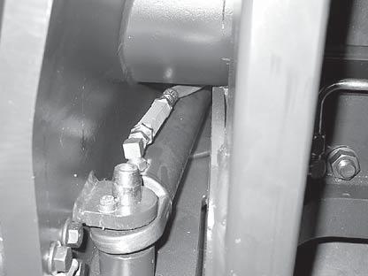
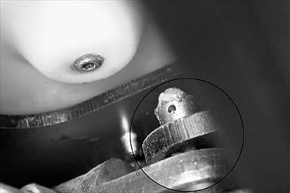
● Drive the bolts out with a plastic hammer and if necessary a soft material mandrel. Do not use steel tools.
● Lift the cylinder out.
Assembly
● Re-assemble the reach cylinder in the reverse order.
● Bleed the hydraulic system (see Chapter 2)
244 ESR4500 06/2004 • Printed in Germany MS-7.0-2140 MAST
M1663
MS-2140-059
Integrated Sideshifter
Disassembly
(See Figure M1500)
● Lower the fork carriage onto a pallet.
● Depressurise the hydraulic system (see Chapter 2 or Chapter 7).
● Switch off the truck and disconnect the battery.
● Place a flat tray underneath to collect any spilled hydraulic oil.
● Remove the load backrest.
● Unscrew the stopper (25) and remove the forks.
● Undo all the hydraulic connections to the sideshifter (seal all ports with filler plugs).
● Unscrew the lug (18).
● Tilt the frame (20) up and slide it from the frame on the side. Make sure you do not push the slide pieces (12) out of their seats in the process.
● Dismantle the cylinder if necessary.
Assembly
● Clean all contact surfaces and lubricate them again.
● Use new seals and deflector rings if have dismantled the cylinder.
● Assemble all components in the reverse order of disassembly.
● Bleed the sideshifter cylinder by moving it from the left to right ends approximately 20 times. The cylinder has an internal valve and is self-bleeding. Bleed the tilt cylinder as usual via the ports (see Chapter 2, note the safety instructions!)
245 ESR4500 06/2004 • Printed in Germany MS-7.0-2140 MAST
246 ESR4500 06/2004 • Printed in Germany MS-7.0-2140 MAST
M1500
CYLINDERS
247 Printed in Germany
page
248 Printed in Germany
Blank
Cylinders
General
Safety when working on hydraulic systems
WARNING
Risk of serious injury from pressurized hydraulic oil.
Pressurized hydraulic oil can penetrate the skin.This is a serious medical emergency which requires immediate medical attention.
The skin will not show any obvious initial damage and the physical effects will not be manifested immediately. Seek medical assistance if your skin has been affected by pressurized hydraulic oil.
For your personal protection:
Depressurise the hydraulic system before starting assembly work on the hydraulic system.
After carrying out assembly work carefully check to see that all ports are tightened before re-pressurising the system.
Wear protective clothing, safety glasses and safety gloves when tracing leaks or bleeding the system.
Use a piece of absorbent paper to trace leaks, never use your hands.
Follow the hydraulic oil manufacturer’s safety instructions when handling these oils.
General Instructions for Repairing Hydraulic Components
Hydraulic systems are sensitive to dirt.
● Thoroughly clean any hydraulic components you have removed before dismantling them and placing them on a workbench.
● Always repair hydraulic components in a clean working environment.
● Immediately protect cleaned and de-greased components with a thin coating of hydraulic oil. Use the same type as is used in the truck.
● Protect all components from re-contaminating until they are installed again.
● Immediately seal any open hydraulic ports on repaired assemblies with filler plugs. This also
applies to the open ports and lines on the truck when you remove any hydraulic components.
● Do not refinish any cylinder surfaces! Replace any damaged components.
● When carrying out repairs always replace all the seals in the assembly. Never recycle seals which have already been used.
249 ESR4500 06/2004 • Printed in Germany MS-8.0-2232 CYLINDERS
Rod Seal Assembly
General
All tools and equipment used for rod seals must be burr-free and not have sharp edges. The tools should be made either of soft metal (aluminium, brass) or a suitable plastic.
Do not use hooks to remove seals. The same rule applies: Burr-free, rounded tips and made of soft metal to avoid damaging the seal seat.
Screwdrivers or similar tools will damage the seal seats and the seals. This will result in leaks.
Large Rod Seal Assembly
Tools required:
● Tool body (outer diameter must fit the internal diameter of the gland).
● Three pins (1, 2 and 3). Pin (1) is fixed; pins (2) and (3) are moveable.
Assembly:
● Apply a thin coating of hydraulic oil to the rod seal and the seal seat in the gland.
● Place the rod seal over the fixed pin (1).
● Bend the rod seal under pin (2) (see Fig. MS2232-019).
To remove rod seals from the lift cylinder and the freelift cylinder, you will require 2 specially produced tools (see Figure MS-2232-016).
If the seal has to be pushed over sharp edges, cracks or nicks, use appropriate protective mechanisms.
Screwdriver, shaft min . 150 mm long, max. 4mm Ø
4mm self-tapping screw
Insulating tape
Hard-soldered screw, soldering joint sanded.
MS-2232-016
We will now demonstrate 2 processes – depending on the seal rod diameter – for ensuring safe assembly.
● Bend the loop created in this way so far up that pin (3) can be pushed into the loop.
● Now push the tool body into the gland until the rod seal is aligned with the seal seat (see Fig. MS-2232-020).
250 ESR4500 06/2004 • Printed in Germany MS-8.0-2140
CYLINDERS
MS-2232-013
1 2
MS-2232-019
3 1 2 3
MS-2232-020
● Pull back pin (3). A section of the rod seal jumps into the seal seat (Fig. MS-2232-022).
Small Seal Rod Assembly
Tools required:
Groove aligning arbor. The outer diameter must fit the internal diameter of the gland. The arbor should end at the bottom of the seal seat.
Arbor to drive in the seal.
● Apply a thin coating of hydraulic oil to the rod seal and the seal seat in the gland.
● Place the gland onto the groove aligning arbor.
● Gently squeeze the rod seal together.
● Place the rod seal at one point of the seal seat.
● Now pull back pin (2). The rod seal is now fully seated in the seal seat.
● Pull the tool body out of the gland.
● Press the rod seal and the arbor into the seal seat.
251 ESR4500 06/2004 • Printed in Germany MS-8.0-2232 CYLINDERS
3
2
MS-2232-022
MS-2232-021
MS-2232-024
CYLINDERS
Rod Seal Assembly, Sealing Lip First
The sealing lip is sensitive and must not be damaged. You therefore require special protective sleeves when pushing the seal over the thread and holes.
Sealing lip assembly direction: Always to the pressure side!
252 ESR4500 06/2004 • Printed in Germany MS-8.0-2140
Bearing ring Protective sleeve Seal Tool
MS-2232-025
Blank page
Printed in Germany 253 SAFETY
254 ESR4500 06/2004 • Printed in Germany MS-8.0-2140
1 2 3 4 5 6 7 8 9 10 11 12 120 - 140 Nm 5 - 6 Nm
CYLINDERS
MS-2140-066
MP-2140-052
Lift cylinder
General
Make sure the components and the working area are clean. Thoroughly clean the cylinder before dismantling it. Hydraulic systems are sensitive to contamination. When carrying out repairs, always replace all the seals and bearing rings. Apply a thin layer of hydraulic oil to all the seals and internal metal surfaces prior to assembly. Use hydraulic oil according to the temperature range of the area of application (see Lubricant table in Chapter 1).
Removal and Assembly
Inspect the piston rod for damage over the full lift height before removing it. Damaged piston rods damage the seals very rapidly. Replace the damaged piston rod whenever you fit new seals.
● Refer to the Mast chapter for the removal and assembly of the lift cylinders.
Dismantling
CAUTION
Possible damage!
The cylinder tube can become damaged when you clamp the cylinder. Do not overtighten the devices for holding the cylinder.
Rod Seal Removal
● Clamp the removed cylinder to prevent it from twisting.
● Unscrew the cylinder cap (8) from the cylinder tube.
● Remove the deflector ring (10), the rod seal (9), the bearing ring (7), the guide ring (5) and the O ring (6) from the cylinder cap.
● Thoroughly clean all metallic components with a suitable light solvent. In particular, the seats of the seals and the bearing rings must be absolutely clean and free of foreign bodies. Apply weak, dry compressed air to the components until they are dry. Immediately protect shiny metal surfaces with a thin film of hydraulic oil (for the oil type refer to the lubricant table in Chapter 1).
Piston Rod Removal
● To replace the guide ring (2), first remove the piston rod. Pull the piston rod from off the cylinder tube.
● Remove the guide ring (2). Take the half shelves (3) off the piston rod.
Assembly
CAUTION
Possible damage!
Incorrect handling during assembly can result in leaks. Take care not to damage the piston rod and the new seals during assembly. Use guide bushing and burr-free tools without sharp edges.
Apply a thin coating of hydraulic oil to all seals and components prior to assembly. Observe the general instructions on assembling seal rods in this chapter.
Piston Rod Assembly
● Insert the half shelves (3) into the groove of the piston rod.
● Pull up a new, lubricated bearing ring (2).
● Push the piston rod into the cylinder tube.
Installing the Rod Seal
● Insert a new deflector ring (10), a new rod seal (9), a new bearing ring (7), a new O ring (6) and a new guide ring (5) into the cylinder cap. Cover threads and sharp edges with suitable means to avoid damage during assembly.
255 ESR4500 06/2004 • Printed in Germany MS-8.0-2232 CYLINDERS
MS-2232-018
Seal seat
CYLINDERS
● Screw the cylinder cap back on, while taking care not to damage the bearing ring (7).
● Torque the cylinder cap to 120 – 140 Nm
● Refit the lift cylinder (see Mast chapter).
● Bleed the cylinder (see Hydraulics chapter).
● Perform a drift test (see Hydraulics chapter).
256 ESR4500 06/2004 • Printed in Germany MS-8.0-2140
Blank page
Printed in Germany 257 SAFETY
258 ESR4500 06/2004 • Printed in Germany MS-8.0-2140
1 2 3 4 5 6 7 8 9 10 11 12 13 14 15 16
CYLINDERS
MP-2140-053
120 - 140 Nm 5 - 6 Nm
MS-2140-067
Free-Lift Cylinder
General
Make sure the components and the working area are clean. Thoroughly clean the cylinder before dismantling it. Hydraulic systems are sensitive to contamination. When carrying out repairs, always replace all the seals and bearing rings. Apply a thin layer of hydraulic oil to all the seals and internal metal surfaces prior to assembly. Use hydraulic oil according to the temperature range of the area of application (see Lubricant table in Chapter 1).
Removal and Assembly
Inspect the piston rod for damage over the full lift height before removing it. Damaged piston rods damage the seals very rapidly. Replace the damaged piston rod whenever you fit new seals.
● Refer to the Mast chapter for the removal and assembly of the free-lift cylinder.
Dismantling
CAUTION
Possible damage!
The cylinder tube can become damaged when you clamp the cylinder. Do not overtighten the devices for holding the cylinder.
Rod Seal Removal
● Clamp the removed cylinder to prevent it from twisting.
● Unscrew the cylinder cap (12) from the cylinder tube.
● Remove the deflector ring (14), the rod seal (13), the bearing ring (11), the guide ring (9) and the O ring (10) from the cylinder cap.
● Thoroughly clean all metallic components with a suitable light solvent. In particular, the seats of the seals and the bearing rings must be absolutely clean and free of foreign bodies. Apply weak, dry compressed air to the components until they are dry. Immediately protect shiny metal surfaces with a thin film of hydraulic oil (for the oil type refer to the lubricant table in Chapter 1).
Piston Rod Removal
● To replace the guide ring (3), first remove the piston rod. Pull the piston rod from off the cylinder tube.
● Remove the guide ring (3). Take the half shelves (4) off the piston rod.
Cushion Removal
● Remove the inner retaining ring (5). Remove the piston (6) and the spring (7) from the piston rod.
Assembly
CAUTION
Possible damage!
Incorrect handling during assembly can result in leaks.Take care not to damage the piston rod and the new seals during assembly. Use guide bushing and burrfree tools without sharp edges.
Apply a thin coating of hydraulic oil to all seals and components prior to assembly. Observe the general instructions on assembling seal rods in this chapter.
Cushion Installation
● Push the spring (7) and the piston (6) into the piston rod.
● Fix the spring and the piston with the inner retaining ring (5).
Piston Rod Assembly
● Place new half shelves (4) on the piston rod and pull up a new guide ring (3).
● Push the piston rod into the cylinder tube.
Installing the Rod Seal
● Insert a new deflector ring (14), a new rod seal (13), a new bearing ring (11), a new O ring (10) and a new guide ring (9) into the cylinder cap. Cover threads and sharp edges with suitable means to avoid damage during assembly.
● Screw the cylinder cap back on, while taking care not to damage the bearing ring (3).
259 ESR4500 06/2004 • Printed in Germany MS-8.0-2232 CYLINDERS
Dichtungssitz
MS-2232-018
● Torque the cylinder cap to 120 – 140 Nm
● Refit the free lift cylinder (see Mast chapter)
● Bleed the cylinder (see Hydraulics chapter)
● Perform a drift test (see Hydraulics chapter)
260 ESR4500 06/2004 • Printed in Germany MS-8.0-2140 CYLINDERS
Blank page
Printed in Germany 261 SAFETY
262 ESR4500 06/2004 • Printed in Germany MS-8.0-2140
1 2 3 3 4 5 6 7 8 9 10 11 12 13 14 15 16 17 17 17 17 18 18 19 20 19 20 21 22 21
CYLINDERS
MS-2140-068
120 - 140 Nm 180 - 200 Nm
MP-2140-047
Reach Cylinder
General
Make sure the components and the working area are clean. Thoroughly clean the cylinder before dismantling it. Hydraulic systems are sensitive to contamination. When carrying out repairs, always replace all the seals and bearing rings. Apply a thin layer of hydraulic oil to all the seals and internal metal surfaces prior to assembly. Use hydraulic oil according to the temperature range of the area of application (see Lubricant table in Chapter 1).
Removal and Assembly
Inspect the piston rod for damage over the full lift height before removing it. Damaged piston rods damage the seals very rapidly. Replace the damaged piston rod whenever you fit new seals.
● Refer to the Mast chapter for the removal and assembly of the reach cylinder.
Dismantling
CAUTION
Possible damage!
The cylinder tube can become damaged when you clamp the cylinder. Do not overtighten the devices for holding the cylinder.
Rod Seal Removal
● Clamp the removed cylinder to prevent it from twisting.
● Unscrew the ball joint (16). Pull the spacer sleeve (22) and the O rings (21) off the piston rod (6). Flange up the safety plate (9) in order to unscrew the cylinder cap. Unscrew the cylinder cap (10) from the cylinder tube.
● Remove the deflector ring (13), the rod seal (12), the bearing ring (8), the guide ring (11) and the O ring (7) from the cylinder cap.
● Thoroughly clean all components with a suitable light solvent. In particular, the seats of the seals and the bearing rings must be absolutely clean and free of foreign bodies. Apply weak, dry compressed air to the components until they are dry. Immediately protect shiny metal surfaces with a thin film of hydraulic oil (for the oil type refer to the lubricant table in Chapter 1).
Piston Rod Removal
● To replace the guide ring (4) and the rod seal (5), first remove the piston rod. Pull the piston rod from off the cylinder tube.
● Remove the guide ring (4). Take the seal (5) off the piston rod.
Assembly
CAUTION
Possible damage!
Incorrect handling during assembly can result in leaks. Take care not to damage the piston rod and the new seals during assembly. Use guide bushing and burr-free tools without sharp edges.
Apply a thin coating of hydraulic oil to all seals and components prior to assembly. Observe the general instructions on assembling seal rods in this chapter.
Piston Rod Assembly
● Place a new seal (5) on the piston rod and pull up a new guide ring (4).
● Push the piston rod into the cylinder tube.
Installing the Rod Seal
● Insert a new deflector ring (13), a new rod seal (12), a new bearing ring (8), a new O ring (7) and a new guide ring (11) into the cylinder cap. Cover threads and sharp edges with suitable means to avoid damage during assembly.
● Screw the cylinder cap back in with a new safety plate (9). Torque the cylinder cap to 120 – 140 Nm. Flange the safety plate, it must lie in the notch of the cylinder cap.
● Push the spacer sleeve (22) and the O rings (21) onto the piston rod. Refit the ball joint (16) with the counternut (15) and washer (14). Do not yet counterfix the nut as the screw depth must still be adjusted on assembly.
263 ESR4500 06/2004 • Printed in Germany MS-8.0-2232 CYLINDERS
CYLINDERS
● Refit the reach cylinder (see Mast chapter)
● Bleed the cylinder (see Hydraulics chapter).
264 ESR4500 06/2004 • Printed in Germany MS-8.0-2140
265 ESR4500 06/2004 • Printed in Germany MS-8.0-2232 CYLINDERS
M1500
Sideshift, Cylinder
INFORMATION
The sideshifter must be removed from the truck in order to repair the cylinder. For removal instructions see chapter 7.
Dismantling
WARNING
Risk of serious injuries from components flying off at high speed.
If you remove the frame (20) and apply the sideshift to extend the piston rods, the piston rods will shoot out like a bullet!
Depressurise the hydraulic system prior to dismantling the cylinder. Prevent the truck from being switched on again. Manually pull the piston rods off the cylinder tube, never force them out at pressure.
● Pull the left and right hand piston rods (6) off the cylinder.
● Push the washers (4) out of the guides.
● Remove the deflector rings (5) and the rod seals (3).
● Remove the slide bearings (2) and the coupling parts (27).
● Thoroughly clean all components and the seal seats with a solvent.
● Remove any burrs from the piston rod ends.
● Replace any components showing signs of grooves or damage.
Assembly
● Lubricate all components with hydraulic oil.
● Note the installation position of the rod seals: Pressure seals are installed with the lip facing the pressure side!
● Re-assemble the cylinder in the reverse order.
266 ESR4500 06/2004 • Printed in Germany MS-8.0-2140
CYLINDERS
ELECTRICAL DIAGRAMS
267 Printed in Germany
page
268 Printed in Germany
Blank
Blank page
269 ESR4500 06/2004 • Printed in GermanyMANY MS-DIA-2140 DIAGRAMS
Blank page
270 ESR4500 06/2004 • Printed in Germany MS-DIA-2140 DIAGRAMS
Blank page
271 ESR4500 06/2004 • Printed in GermanyMANY MS-DIA-2140 DIAGRAMS
Blank page
272 ESR4500 06/2004 • Printed in Germany MS-DIA-2140 DIAGRAMS
Drive
ESR4500 06/2004 • Printed in Germany MS-DIA-2140 273 DIAGRAMS
- AC System FU 7 = 425 A FU 1 = 15 A 48 V BATT. 3 M2 Motor-Shunt Motor-Shunt +48 +5 B+ BUBI_Mess I_Mess U_Mess U_Mess U_Mess U_Batt Control U V W S+ 12 V Ch. A Ch. B Gnd 3 5 6 4 T THS 2 PTC Temp GND17 12 21/13 8/7 23/22 1+ FAN KYS CAN_H CAN_L CAN_Gnd ID GND ID1 Card BV+ FU 2 = 15 A HORN HNS UBVCM HDMHydraulic
8 23 22 Lift/lower Reach Sidesh. 5th. funct Tilt Acc.- Pedal 12 V O CAN_H CAN_L CAN_Gnd UT Ain 1 Ain 2 Ain 3 Ain 4 Ain 5 Ain 6 GND_OUT 6 21 35 36 37 20 34 7 28 RES 1 L+ LRES 2 L+ LGND GND Di 9 HGT(R)S Di 16 FLS/LCS Di 3 RS Di 4 ACS Di 5 SPS Di 7 RES 1 Di 1 SES Di 10 BFS Di 11 BPS Di 12 BRS Di 2 FS Di 15 ORS Di 6 KYS L+ UBp 1 2 3 4 CHNL A CHNL B B+5V ECR 5 LS Di 14 Ch B Di 13 Ch A 38 9 25 4 5 16 2 19 32 3 33 40 POUT_14 POUT_1 POUT_3 POUT_4 POUT_5 POUT_6 POUT_7 POUT_8 POUT_15 ED1 POUT_2 POUT_11 POUT_9 42 1 15 29 13 27 41 12 26 1 2 3 to SDM, TDM & Display 120 Ohm CAN_H CAN_L CAN GND to TDM to TDM & Display D A B Height Encoder LIGHTING K1,2 Kn... BRAKE FU6 FU5 15A 15A C K 2 KEY KYS and SDM 18 17 CAP 15/14 Temp 16 to Display E 4 3 2 1 S+ 12 V GND S1 ECR 2 SPEEDSENSOR Z Z Di 8 RES 2 39 PLS Di 17 PLS G CA 205 AN_21 BLS12 AN_22 LS/FKS 13 C digital input 11 10 24 Travel alarm Beacon F F UBEDS G FAN 2 HDM EDS mechanical) Pin 2 2 B COLDSTORE POWER SUPPLY K 5 K 6 OPTIONS + 12 V Display GND Display HORN K7,8 - BV K8 FU6 LAMP G K10 G K9,10 - BV FU5 OPTIONS K 1 K 4 K 3 K7 K9 K1 F1V1Charge-R1 C5 V5 R2 1 K11 ED1 ED1 30 31 CA 205 CA 206 CA 205 Module Ch B Ch. A FAN 3 FAN 4 2 x 24 V POT 1 POT 2 POT 3 POT 4 POT 5 POT 6 PVL SVH PVRE PVRT PVAL PVAR SVT SVS SV5 CA 201 CA 201 G CA 422 CA 604 CA 601 CA 801 2942 2938 2943 2921 CA 802 CA 801 2941 2939 206 207 206207 29532954 2955 2956 2957 2958 508 509 510 511 2921 CA 422 2906 2907 2913 019 017 002 003 004 018 022 001 007 008 009 005 023 2917 2915 2916 2911 2914 2910 027 316 622 028 317 623 315 314 CA 604 310 CA 422 CA 422 2909 021 020 024 CA 422 CA 604 029 2949 CA 604 CA 422 2942 2921 2940 5902 300 305 304 303 302 301 306 106 101 102 103 104 105 600 605 604 603 602 601 606 504 113 313 310 CA 440 CA 440 900 905 614 512 2959 2935 5920 5913 29252960 513 006 5911 CA 422 CA 604 CA 801 CA 601 5921 5922 5923 5924 5926 5925 5910 5909 5907 5908 5906 5905 5904 5903 2948 2947 2946 2945 2944 2930 200 201202 2951 2901 9 2 10 2904 29025928 5902 START UP CARD 2923 501 5914 5901 2928 2927 2926 203 / 204 293129322933 591559165918 5919 5919 2929 903/904 908/909 617/618 607 625 319 900/901 905/906 614/615 500 / 505 506 508 / 509 510 511 307 010 011 608 609 107 CA 6 CA 604 04 CA 4 CA 422 22 CA 402 4 12 3 11 CA 422 2 A 4 3 3 C 14 8 1 13 4 14111017 32 31 12 6 8 9 10 16 12 11 11 1 55 5 1888 2 6 7 3 4 5 9 7 6 14 112 7 BR-LIGHT OUT V2 C1,2 12V OP 48V I/P 0V OP 0V I/P 1 2 3 4 DC/DC 14 6 5 4 BVCA 600 PC 416 CA 428 1 2 CA 419 A C CA 417 A C CA 406 A C CA 404 A C 1 1 1 1 1 3 3 3 3 3 3 1 2 2 2 2 2 2 CA 418 CA 407 CA 408 CA 409 CA 410 CA 411 CA 807 1 3 CA 808 2 CA 810 2 CA 809 2 CA 811 2 CA 811 1 CA 809 1 CA 810 1 CA 808 1 CA 807 2 CA 426 A C 2918 CA 805 A B C CA 806 1 2 3 48 V CA 434 1 CA 435 2 CA 415 1 CA 401 1 CA 415 2 CA 401 2 CA 421 1 3 CA 421 4 CA 421 2 CA 433 2 1 CA 433 4 3 CA 429 2 3 1 4 CA 430 1 2 6 3 CA 600 CA 601 4 5 CA 601 CA 600 CA 803 4 2 3 15 1 4 2 3 1 CA 801 9 10 CA 601 9 10 CA 422 6 33 503 4 2 CA 420 A 1 CA 420 C 29962997 2 K12K13 K13 K12 UB502 2924 927 4 Relay-Options CA 812 B A C FKS ORG BRN BLK RED Option 2960 2959 813134_2I_sh1
Wiring Diagram
Wiring Diagram - AC System

ESR4500 06/2004 • Printed in Germany 274 MS-DIA-2140
813134_2I_sh2 B+ MOTOR STEPPER 3 M1 Motor-Shunt Motor-Shunt B+ BUBI_Mess I_Mess U_Mess U_Mess U_Mess U_Batt Control U V W S+ 12 V Ch. A Ch. B Gnd T THS 1 PTC Temp GND Card TDMTraction Drive Module B to "A" A SDM Steering Drive Module 11 10 3 CAN_GND to VCM, D FU 4 = 30 A B+ BBUB8 7 1 2 SFS 1SA L+ LSFS 2 L+ LGND GND C to "C" DI 1 SFS 1 SA DI 2 SFS 2 3 M3 R S T DC Steering ECR 3 STEERING HALL C HALL A +5 V DC HALL B COMM Ain 1+ Ain 1+5 V out Ain 2+ Ain 25 6 P5 P6 P4 P2 P1 P3 HDM & PC 416 BV+ BV+ Key 12 V Out GND UBCAN_GND CAN_L CAN_H µ proc. with ext. memory 256 k D Temp CAP 13 14 15 16 4 E 4 3 2 1 S+ 12 V GND ECR 1 SPEEDSENSOR ECR 4 Z Z BRAKE 9 V3 FU 3 = 15 A 12 V Out 11 V GND Z C Ch. B Ch. A 123456 1 2 3 4 204 / 205 204 205 2903 2950 59275912 29362937 025 619 026 311 312 505 506 CA 204 618 909 904 109 110 111 112 700701 702 803802801 612 309 016 015 014 2905 902/903 907/908 616/617 3 5 6 4 16 17 308 012 013 610 611 108 19 16 14 20 1/4 2/5 3/6 15 17 CA 204 CA 204 CA 202 CA 202 CA 203 202 2908 318 319 507 906/907 901/902 615/616 613 624 1 2 3 4 123456 CA 413 CA 437 CA 412 CA 436 CA 425 2 3 1 4 CA 427 1 2 12 21/13 8/7 23/22 1 15/14 620 CA 439 A B C CA 438 1 2 3 5 CA 402 6 Integrated in START UP CARD CA 402 13 CA 402 14 CA 402 B CA 431 A CA 431 CA 414 3 4 1 6 2 5 18 CA 203 4 CAN_H CAN_L 120 Ohm DISPLAY 1 2 3 4 5 6
DIAGRAMS
ESR4500 06/2004 • Printed in Germany MS-DIA-2140 275 DIAGRAMS Wiring Diagram Option COLDSTORE 30 85 86 87 87a +RELAY_24 V 30 85 86 87 87a +RELAY_24 V COLDSTORE (48 V) 30 85 86 87 87a +DRIVING LIGHTS 12V RELAY_12 V 30 85 86 87 87a +WORKING LIGHTS 12V RELAY_12 V 85 87 30 86 85 87 3 1 2 5 3 1 2 5 BRAKE LIGHTS 12 V 30 85 86 87 87a +RELAY_24 V 30 85 86 87 87a +RELAY_24 V 30 86 85 87 30 86 85 87 24V O/P 48V I/P 0V O/P 0V I/P DC/DC DC/DC_24 V 12V O/P 48V I/P 0V O/P 0V I/P DC/DC DC/DC_12 V 123456 12 11 10 9 8 7 FU1FU2FU3FU4FU5FU6 FUSE_BOX from MAIN HARNESS +48 V BV THS3 Heater Assy Brake lights 2 x 12 V/21 W Working 2x 12 V / 55 W SW Converter Converter - BV Sig. GND OPTIONS Options OPTIONS Options cabin WINDSCREEN WIPER INTERIOR LIGHTING XENON FLASH Br-Light out TRAVEL ALARM HORN K7,8 K8 POUT_11 (VCM) - BV LAMP BEACON POUT_14 (VCM) Connect to MAIN LOOM Connect to OPTION LOOM PC 421 PC 433 2x 12 V / 55 W VIDEO CAMERA MONITOR - BV + 48 V Supply OPTIONS 12/24 VCABIN 12 V ADD (3) (1) (2) (5) (3) (1) (2) (5) Tail Lights Parking Lights Head Lights Lights SD GND 12V (632) 2 1 GND 12V SI 4x 12 V / 10 W Indicator INDICATOR MODUL 49 3149a K1 K2 K4 K3 K5 K6 522 2962 523 2963 333 632 337 637 636 336 335 341 334 635 342 634 339 344 633 346 345 343 332 340 347 631 338 526 921 922 331 2961 2960 2966 2964 2965 2967 2968 920 2969 520 521 525 524 380 from FU6 K9,10 from FU5 - BV K10 PC 433 BEACON PC 421 TRAVEL ALARM after ED1 S2 (FU2) K7 K9 2 CA 440 1 CA 440 3 CA 440 4 CA 440 8 511 2958 2957 2955 2956 1 PC 446 2 1 CA 447 2 5 CA 447 4 36 5 36 JC 447 4 1 JC 447 2 5 CA 441 6 1 2 CA 441 CA 441 3 4 CA 441 11 CA 442 12 CA 442 10 CA 442 5 CA 442 6 4 7 CA 442 3 1 CA 442 3 CA 443 4 1 CA 443 2 CA 443 4 PC 444 2 PC 444 3 PC 445 1 PC 445 1 2 4 CA 421 3 CA 421 1 3 CA 433 2 4 CA 433 CA 443 CA 442 7 CA 440 510 - BV 5 CA 440 6 CA 440 508 509 Working Lights 24 V 2 x 24 V / 70 W 1 JC 440 2 SW Heater R1-R10 642 / 643 354 355 544 2995 2990 29912992 541 642 643 354 355 544 2995 2954 2953 K13 K12 2997 2996 29592960 ED1 3 4 K13 K12 - BV 3 4 5 6 7 8 CA 441 4 1 1 CA 449 4 CA 449 CA 448 CA 448 4 3 CA 448 3 CA 449 4 CA 450 5 CA 451 1 1 5 CA 448 4 2 CA 449 4 2 CA 450 4 CA 451 4 CA 451 2 CA 450 1 2 R = 33 Ohm/25W 1 7 CA 206 2 8 12 CA 442 CA 442 648 647 371372 12 CA 442 647648645644 646 631 638 8 651 647 2 648 CA 442 646 631 368367366365 376375370369 373374 644 364 645 363 651 361 638 646/649 362 357 356 545 349348 640639 360 359 358350 351 1 3 4 2 330 381 2x 12 V / 10 W 2x 12 V / 4-5 W 652 651 630 CA 442-2 GND to GND 12V (630) to GND 12V (630) 2x GND 2x +12V +12/24V GND KEY KYS ED-sw 201 2951 2901 CA 420 A CA 420 C 2924 to SP1 30 86 813383_2D
Wiring Diagram Coldstore Cabin
ESR4500 06/2004 • Printed in Germany 276 MS-DIA-2140
12V O/P 48V I/P 0V O/P 0V I/P DC/DC DC/DC_12 V 123456 12 11 10 9 8 7 FU1FU2 FU3 FU4 FU5 FU6 FUSE_BOX from MAIN HARNESS Converter - BV 522 2962 630 632 381 637 330 PC 421 TRAVEL ALARM 3 CA 440 2957 1 CA 447 2 4 CA 447 5 36 1 PC 445 4 7 CA 440 510 355 / 643 354 / 642 544 2995 2 2 2954 K13 2997 2960 3 2 652 337 651 333 SP25 +12 V +12V PC 433 BEACON 2955 2953 K12 2996 2959 2956 CA 440-2 SP26 GND 12 V CA 442-4 380 CA 442-2 FU 7 = 425 A 48 V BATT.+ + EDS NOT-AUS S1 S2 Screw Screw ED1 BUS-BAR BUS-BAR CA 440-1 - BV Options cabin Coldstore - BV + 48 V 523 2963 8 CA 440 4 511 2958 4 CA 446 3 2 1 87z 31 15 87 +87a +30 K14 Loom 48 V M SW_R Windscreen wiper REAR M SW_F Windscreen wiper FRONT SW_I Interior Lighting 1 CA 458 2 1 CA 457 2 Heater screen FRONT H. Heater screen REAR H. Heater screen LEFT SIDE H. Heater screen RIGHT SIDE H. Heater screen TOP H. SW_H FU 8 = 30 A FU 9 = 50 A SW_D M 48 V / 1500 W 48 V / 225 W 48 V / 126 W 48 V / 168 W 48 V / 304 W 48 V / 380 W FAN GND +12V GND 87z 15 31 87 1 CA 459 1 CA 460 1 CA 461 1 CA 462 1 CA 463 2 CA 459 2 CA 460 2 CA 461 2 CA 462 2 CA 463 48 V 10-20 W 2x 12 V / 5 W 12 V / 60 W 12 V / 60 W SPS SW SPS A JC 419 B FU2 SP9 2914 +48 V BV C 005 VCM (CANION) Connection to Harness main loom 812909 A CA 465 B C +12 V COMPONENTS ASSEMBLY HEATER SCREEN ASSEMBLY HEATER / FAN ASSEMBLY CA 464 CA 464 SW Heater SW door cabin TIME DELAY RELAY + 48 V int.-SW S2 S1 Screw Screw ED3 Contactor + 48 V S2 S1 Screw Screw ED2 Contactor ED2 ED3 ++ RED BLACK Connection to Beacon Loom 813524 2985 538 4 3 2 1 KEY KYS EDS 201 2951 2901 CA 420 A CA 420 C K13 K12 UB502 2924 927 Relay-Options SP1 BEACON 30 - BV (Controller traction) PC 467 4 3 2 1 CA 466 GND GND - BV (Controller traction) GND GND Connection Point Connection Point Connection Point C B A CA 456 SW_HS 4 3 2 1 JC 446 HEATED SEAT V.01 207 206 203 200 220 221 222 223 555550 551 29113 29120 29119 050 559 29117 558 661 393 29118 390 392 29116 29114291102911129112 29115 557 554 553 552 556 660 391 662 394 663 395 664
DIAGRAMS
814564_2A_Wiring diagr. coldstore cabin
The following table contains the numbers of the wire harnesses used on the ESR4500. The list contians the wire harness number and a reference to the area in which the wire harness is located.
277 ESR4500 06/2004 • Printed in GermanyMANY MS-DIA-2140 DIAGRAMS
Item No.Assigned toPage 812909Main Harness297,280
Reach
813524Harness Options285 813774Harness Beacon Switch287 813485Harness Cold store288 813526Harness Working Light 12V289 813779Harness Working Light 24V290 813836Harness Driving Light291 813527Harness Travel Alarm292 814056Harness
12V/24V Supply to b/w Monitor296
Monitor or Connection Box to Connector Panel297 814407Harness
to Reach Carriage298 814408Harness
814498Harness
812326Harness Connector Panel to Reach Carriage283 812327Harness
Carriage284
DC/DC Converter with Harness Options 813445293 813753Har ness DC/DC Converter without Harness Options 813445294 814430Harness Heated Seat295 814405Harness
814499Harness s/w
(Camera) Connector Panel
(Camera) Reach Carriage to Mast299 814521Harness (Camera) Mast to Camera300
(Camera) TFT Display to Connection Box301 814526Harness 12V Supply to Connection Box302 814475Harness and Installation Drawing 6th Function303
814337Har ness Davis Derby System304
814565-001Harness 1 Coldstore Cabin307 814565-002Harness 2 Coldstore Cabin308
Blank page
278 Printed in Germany
ESR4500 06/2004 • Printed in Germany MS-DIA-2140 279 DIAGRAMS PINWire No. Wire No. Wire No. Wire No. Wire No. Wire No. Wire No. Wire No. Wire No. Wire No. Wire No. Wire No. Wire No. Wire No. Wire No. 1303 2103 3603 4 PC 409 (POT4 TLT) PC 408 (POT3 Reach) Fuse No.PIN FU 1 1200 15 A / 80 V7201 / 202 FU 2 2203 / 204 15 A / 80 V82926 FU 3 3204 15 A / 80 V92903 FU 4 4205 30 A / 80 V102936 2937 FU 5 5206 15 A / 80 V11295 FU 6 6207 15 A / 80 V12295 FUSE-BOX PIN 12931 25915 PC 401 (FAN 1) PIN 12929 25919 3307 12 V + 4608 GND 5010 CH. A 6011 CH. B 7617 CAN GND 8618 CAN GND 9 10 11 12 13 14908 CAN L 15909 CAN L 16107 TMP 17609 TMP GND 18 19 20 21 22903 CAN H 23904 CAN H PC 201 Pump (HCM) PIN 12905 23308 12 V + 4610 GND 5012 CH. A 6013 CH. B 7616 CAN GND 8617 CAN GND 9 10 11 12 13 14907 CAN L 15908 CAN L 16108 TMP 17611 TMP GND 18 19 20 21 22902 CAN H 23903 CAN H PC 202 Tract. (TCM) PIN 12902 2 1 590 ED1 (LINE-CONT.) PIN 12932 25916 PC 415 (FAN 2) PIN 1302 2102 3602 4 PIN 1304 2104 3604 4 PC 410 (POT5 SS) PIN 1305 2105 3605 4 PC 411 (POT6 AUX) PINWire No. Wire No. Wire No. Wire No. Wire No. Wire No. Wire No. Wire No. Wire No. Wire No. 1301 + 2101 S 36014 PC 407 (POT2 Lift) 505 B506 B618 CAN GND 700 025 SFS 1 A 026 SFS 2 2936 B+ 2937 B+ 5912 BRAKE 909 CAN L 904 CAN H 109 A1 + 110 A1111 A2 + 112 A2PC 204 (SDM) 5904 SVH 001 SES 002 FS 003 RS 004 ACS 300 12 V + 600 12 V 614 CAN GND 020 ECR 5 A 5920 BEACON 5910 5908 2930 B+ 5905 005 DMS 2909 018 RES 1 022 RES 2 104 106 900 CAN H 905 CAN L 245902 ED1 25017 FLS / LCS 26 21 20 22 18 17 19 23 5911 275907 28 504 B295906 PVRT 30019 HGT(R)S 31007 32008 BPS 33009 BRS 34105 35101 LIF 36102 a. 37103 TIL 38021 ECR 5 39024 PLS 40023 ORS 415909 425903 PC 205 006 BLS 113 LS 1 2 3 4 5 6 7 8 9 10 11 12 13 14 15 16 1 2 3 4 5 6 7 8 9 10 11 12 13 14 15 16 1 2 3 4 5 6 7 8 9 10 11 12 13 14 15 16 PC 206 (VCM) 1109 P1 2701 P5 3110 P3 4111 P4 5702 P2 / P5 6112 P6 PC 414 (ECR 4) PIN 12911 2009 PIN A5914 BC501 PC 405 PIN A2907 BC003 PC 406 (RS) (HNS) PIN A2906 BC002 PC 404 (FS) S 200 / 206 207 S1 (LINE-CONT.) Power B+ 1014 B 2015 C 3 016 A 4309 5 V+ 56612 GND PC 412 (ECR 3) PC 413 (SDM) PIN 1801 2802 3803 4K6 PIN Wire No. PIN Wire No. PIN Wire No. PIN 1906 CAN L 2 901 CAN H 3615 CAN GND 4907 CAN L 5902 CAN H 6616 CAN GND 7 8 9 10 11 12 13 14 318 11 V+ Output 15624 GND B16319 11 V+ Output 17 182908 B+ KEY 19202 B+ perm. 20 507 GND BPC 203 (Display) K5 K S 1500 / 505 506 (HCM) B12910 ORS 2023 (ORS) PIN 1201 22951 EDS (aux. Contactor) PIN 12904 22923 35901 42927 55912 62903 750 8292 9-10-115914 122928 135927 142950 15-16-PC 402 PIN PIN Wire No. PIN A2951 BC2901 PC 420 (KYS) (BRS) 180 180 Wire No. PIN 1900 901 CAN H 905 906 CAN H 2 3 4 614 615 CAN GND5319 11 V+ 6625 GND Display PC 416 (CAN-CON.) Wire No. S 1205 (HCM) B+ S 2 203 / 2923 S2 (LINE-CONT.) Power B+ K1 K1 S 1508 / 509 / 510 511 (HCM) BPIN 12925 25913 32960 4513 PC 421 (Travel Alarm) 607 607 5902/5928 2902 5928 SP12 SP13 SP3 SP8 SP1 SP5 SP6 SVS PVAL PVRE KYS POT 5 POT 1 SV5 PVAR POT 6 POT 2 POT 3 POT 4 SVT PVL 5913 Travel AL. B 3 8 8 8 3 8 8 8 2960 2997 2959 2996 2996 2924 927 2953 2997 927 502 2954 RELAY-OPTIONS K12 K13 Start up Card SP4 SP7 (VCM) 110 109 wire wire wire 110 wire 109 Main Harness 812909_2R_Main-loom_sh1
DIAGRAMS
ESR4500 06/2004 • Printed in Germany 280 MS-DIA-2140
812909_2R_Main-loom_sh2 Wire No. 2901 2904 2905 2908 2909 after Key B+ PINWire No. 12917 2001 PC 428 (SES) PINWire No. 12928 25901 (HORN) PINWire No. 1306 2106 3606 4 PC 418 (POT1 ACC) PINWire No. 1308 2012 3013 4610 PC 425 Tract. (ECR 1) PINWire No. 1108 2611 PC 427 (THS1) PINWire No. 12915 2007 (BFS) PINWire No. A2913 B C004 PC 417 (ACS) PINWire No. A2914 B 3005 PC 419 (DMS) PINWire No. 1014 B 2015 C 3016 A 4309 5 V + 56612 GND PC 436 Steer (ECR 3) PINWire No. 1801 2802 3803 4PC437 (SDM) PIN 1307 2010 3011 4608 PC 429 Pump (ECR 2) PIN 1107 2609 PC 430 (THS 2) PINWire No. 12916 2008 (BPS) Cr PINWire No. 1910 25918 PC 435 (FAN 4) PINWire No. 12933 2910 PC 434 (FAN 3) 700 701 702 SP7 5 V + PINWire No. A2918 B C006 PC 426 (BLS) PINWire No. A2950 B5927 C PC 431 (Brake) PINWire No. 1311 + 12 V 2 3 PC 439 (SFS 1 SA) PINWire No. 1312 + 12 V 2 3 4 PC 438 (SFS 2) 5915 5916 5918 5919 K8 K9 318 310 311 312 K10 K11 PINWire No. 15909 2019 HGT(R)S 3017 FLS LCS 4022 RES 2 55910 6310 12 V + 7613 GND 12 V85903 95904 105905 115907 125908 13018 RES 1 142921 + BV 15503 GND -BV 165906 17024 PSL 185911 19--20--21--22--23--24--25--26--27--28--29--30--31020 ECR 5 A 32021 ECR 5 B 33113 LS 34coldstore 35coldstore 36--37 38 39--40--PC 422 (MAST) 624 613 619 620 625 Wire No.Wire No.Wire No. Wire No. Wire No. Wire No. Wire No. Wire No. Wire No. Wire No. Wire No. Wire No. Wire No. 2952 2913 2914 2915 2916 2917 2918 PINWire No. 12955 22956 32957 42958 5508 6509 7510 8511 PC 440 OPTION (+/-BV) 300 301 302 303 304 305 306 2926 2927 2929 2930 2931 2906 2907 2910 2911 2952 2932 SP3 after ED1 (FU2) SP9 after ED1 (FU2) SP10 11 V + DisplaySP11 GND Display 2925 2935 500 501 502 503 504 507 512 513 SP4 GND B2953 2955 2956 2959 2954 2957 2958 2960 PINWire No. 12935 25920 32959 4512 PC 433 (BEACON) 600 601 602 603 604 605 606 SP6 GND 12 V619 GND 025 Sig. 2924 coldstore R 9 coldstore R 9 coldstore R 10 coldstore R 10 coldstore R 8 coldstore R 8 SP12 after FU5 (Option)SP13 after FU6 (Option) SP8 SP1 SP5 +12V SP11 SP10
STARPOINTS
SVT SVS PVL SVH PVRE PVAR PVAL PVRT SV5 2933 C 2921 620 GND 026 Sig.A B C SP9
Harness
SP9
SP
Main
793217-022
793217-027
793217-022
793217-027
793217-022
793217-027
793217-022
793217-027
793217-022
793409-00x
793217-022
793217-027
793217-022
793217-027
793217-022 813444-001
793217-037
793409-00x 793217-038
793409-00x
793217-036
793409-00x 793217-035
793409-00x 793217-034
814151
814152 814151
803450-26
814154-001
814154-002
814320-001
814320-002
814154-001
793217-039
793217-040
812909_2R_Main-loom_sh3_PARTS
Pins RequiredHousing Connector
Anti BackoutPin No.
792881-001
PC4012 792883
PC40216116858
793091-001 116851
792881-002793091-002
PC4043792883
792881-002
793091-002
PC4053792883
792881-002
793091-002
PC4063792883
792881-003
793091-003
PC4074792883
792881-003
793091-003
PC4084792883
PC4094792883
792881-003793091-003
792881-003
793091-003
PC4104792883
792881-003793091-003
PC4114792883
814137
PC4126814139
PC4134814141
814140
814157-001
PC4146814158-001
792881-001
793091-001
PC4152792883
792881-004
793091-004
PC4166792883
792881-002
793091-002
PC4173792883
792881-003
793091-003
PC4184792883
792881-002
793091-002
PC4193792883
792881-002
793091-002
PC4203792883
792881-003
793091-003
PC4214792883
812339-001
PC42240792883
PC4254814143
814142
792881-002
793091-002
PC4263792883
814144
PC4272814143
792880-001
793090-001
PC4282792882
PC4294814143
PC4302814143
814142 814144
793217-042 793217-041 812909_2R_Main-loom_sh4_WIRE
792880-002
793090-002
PC4313792882
792881-003
793091-003
PC4334792883
792881-001
793091-001
PC4342792883
PC4352792883
792881-001793091-001
GND
PC4366814147
PC4374814149
814145 814148
792881-003
793091-003
PC4384792883
792881-002793091-002
PC4393792883
PC4408
793091-005
792881-005
4--PC 204 1505 B-Screw M8 B-Ring-T 2506 B-Screw M8 B-Ring-T 3 618 CAN GND PC 2018 4700 5V+SP 7--5 025 SFS 1SA PC 439C 6026 SFS2PC 4383 72936 B+FUSE BOX10 82937 B+FUSE BOX10 95912 BRAKEPC 4025 10909
ESR4500 06/2004 • Printed in Germany MS-DIA-2140 281 DIAGRAMS from Connector Pin-No.: Pin-No.: Wire-No.: to Connector from Connector Pin-No.: Pin-No.: Wire-No.: to Connector PCPC 201 12929SP 3--- 205 1PC 4229 25919SP 8--- 2PC 4282 3307 12V+PC 4291 4 PC 406C 4608 GNDPC 42945PC 417C 5010 CH. APC429 26SP 5--6011 Ch. BPC 42937SP 6--7 617 CAN GND PC 20288PC 4163 8 618 CAN GND PC 20439PC 42231 12607PC 2011310PC 4332 13607PC 20112 11PC 4212 14908 CAN LPC 2021512PC 4225 15909 CAN LPC 2041013PC 42212 16107 TMPPC 4301 14SP 3--17 609 TMP GND PC 430215PC 42210 22903 CAN HPC 2022316PC 419C 23904 CAN HPC 20411 17SP 1--PC 202 12905SP 1---18PC 42213 2---------19PC 4224 3308 12V+PC 425120PC 4102 4610 GNDPC 425421PC 4182 5012 Ch. APC 425222PC 4161 6013 Ch. BPC 4253 25PC 4223 7 616 CAN GND PC 203626PC 42218 8 617 CAN GND PC 201727PC 42211 14907 CAN LPC 203428SP 4--15908 CAN LPC 20114 29PC 42216 16108 TMPPC 427130PC 4222 17 611 TMP GND PC 427231BFS 22902 CAN HPC 203532BPS 23903 CAN HPC 20122 33BRS PC 203 1906 CAN LPC 4162 34PC 4112 2901 CAN HPC 4161 35PC 4072 3 615 CAN GND PC 4163 36PC 4082 4907 CAN LPC 20214 37PC 4092 5902 CAN HPC 20222 38PC 42232 6 616 CAN GND PC 2027 39PC 42217 14318 11V+SP 10--40ORSCrimp Crimp Crimp Crimp 15624 GND B-SP 11--41PC 4221 16319 11V+PC 4165 42 A 5904 SVH 001 SES 003 RS 004 ACS 300 12V+ 600 12V614 CAN GND 020 ECR 5 5920 Beacon 5913 Travel AL. 5910 SVS 5908 PVAL 2930 B+ 5905 PVRE 005 SPS 2909 KYS 018 RES 1 022 RES 2 104 POT 5 106 POT 1 900 CAN H 017 FLS/LCS 5911 SV5 5907 PVAR 504 B5906 PVRT 019 HGT(R)S 007 BFS 008 BPS 009 BRS 105 POT6 101 POT2 102 POT3 103 POT4 021 ECR 5 B 024 PLS 023 ORS 5909 SVT 5903 PVLPC 4228 18 2908 B+ KEY SP 1--- PC 206 12006 BLSPC 426C 19202 B+FUSE BOX713113 LSPC 42233 20507
APC
CANION DISPLAY VCM HDM TDM SDM VCM
B-SP
CAN LPC 20115 11904 CAN HPC 20123 13109 A1+PC 4141 14110 A1-PC 4143 15111 A2+PC 4144 16112
416
792883 812909_2R_Main-loom_sh4_PARTS WIRE_TABLE PARTS_TABLE PARTS_TABLE PC201 PC202 PC203 PC204 PC205 PC206 Screw M8 B- HDM Screw M8 B- HDM Screw M10 S2 Power B+ FUSE-BOX Screw M10 S1 Power B+ Screw M8 B+ HDM Relay-Options BPS BFS EDS ED1 ORS BRS HORN Label Con. Wire 109 & 110 Pins 2 2 2 2 2 2 2 12 8 1 1 1 1 1 16 13 12 15 42 (36 small / 6 medium) (8 small 7 medium) 2 Housing Part-No.: 806702 811996-001 814150 814150 803450-25 814153 814155
814153
Pin
P.-No.:
Connector Table
PC 401 12931SP3--- PC 422 15909SVTPC20541 25915SP8---2019HGT(R)SPC20530
PC 402 12904SP1---3017FLS/LCSPC20525 22923ScrewM10S2Ring-T4022RES2PC20519 35901HORNCrimp55910SVSPC20512 42927SP3---6310+12VSP10--55912PC20497613GNDSP11--62903FUSEBOX985903PVLPC20542 92902ED1Crimp95904SVHPC2051 105928ED1Crimp105905PVREPC20515 115914PC405A115907PVARPC20527 122928HORNCrimp125908PVALPC20513 135927PC431B13018RES1PC20518 142950PC431A142921+BVSP9---
PC 404 A2906SP3---15503-BVSP4--C002PC2053165906PVRTPC20529
PC 405 A5914PC4021117024PLSPC20539 C501SP4---185911SV5PC20526
PC 406 A2907SP3---31020ECR5APC2059 C003PC205432021ECR5BPC20538
PC 407 1301+12VSP5---33113LSPC20613 2101SPC20535 PC 425 1308PC2023 3601GNDSP6---2012PC2025
PC 408 1302+12VSP5---3013PC2026 2102SPC205364610PC2024 3602GNDSP6--- PC 426 A2918SP9---
PC 409 1303+12VSP5---C006PC20612 2103SPC20537 PC 427 1108PC20216 3603GNDSP6---2611PC20217
PC 410 1304+12VSP5--- PC 428 12917SP9--2104SPC205202001PC2052 3604GNDSP6--- PC 429 1307PC2013
PC 411 1305+12VSP5---2010PC2015 2105SPC205343011PC2016 3605GNDSP6---4608PC2014
PC 412 1014BPC4361 PC 430 1107PC20116 2015CPC43622609PC20117 3016APC4363 PC 431 A2950PC40214 4309+5VPC4364B5927PC40213 6612GNDPC4366 PC 433 12935SP9---
PC 413 1801PC437125920PC20510 2802PC437232959FUSEBOX11 3803PC43734512SP4---
PC 414 1109P1PC20413 PC 434 12933SP9--2701P5SP7---2910PC4351 3110P3PC20414 PC 435 1910PC4342 4111P4PC2041525918SP8--5702P2/P5SP7--- PC 436 1014BPC4121 6112P6PC204162015CPC4122
PC 415 12932SP3---3016APC4123 25916SP8---4309+5VPC4124
PC 416 1900/901CANHPC205/2032226612GNDPC4126
2905/906CANLPC205/203231 PC 437 1801PC4131 3614/615GNDPC205/2038/32802PC4132 531911V+PC203163803PC4133
6625GNDSP11--- PC 438 1312+12VSP10---
PC 417 A2913SP9---2620GNDSP11--C004PC20553026Sig.PC2046
PC 418 1306+12VSP5--- PC 439 A311+12VSP10--2106SPC20521B619GNDSP11--3606GNDSP6---C025Sig.PC2045
PC 419 A2914SP9--- PC 440 12955SP12--C005PC2051622956SP12---
PC 420 A2951EDSCrimp32957SP13--C2901SP1---42958SP13---
PC 421 12925SP3---5508ScrewM8HCMRing-T 25913PC205116509ScrewM8HCMRing-T 32960FUSEBOX127510ScrewM8HCMRing-T 4513SP4---8511ScrewM8HCMRing-T
1200ScrewM10S1Ring-TRing-T200206/207FUSEBOX156 7201/202EDSPC203Ring-T19Ring-T2032923FUSEBOX/PC4022/2 2203/204ScrewM10S2Ring-TRing-T205FUSEBOX4 82926SP3---Ring-T500505506SP4PC204---/1/2 3204FUSEBOX3 92903PC4026
4205ScrewM8B+Ring-TCrimp2911SP3--102936/2937PC2047/8Crimp009PC20533 5206ScrewM10S1Ring-TCrimp2910SP3--112959/2996PC433RelayOpt.3/30Crimp023PC20540 6207ScrewM10S1Ring-TCrimp2928PC40212 122960/2997PC421RelayOpt.3/30Crimp5901PC4023 Crimp201FUSEBOX7C rimp2915SP9--Crimp2951PC421ACrimp007PC20531 Crimp2902PC4029Crimp2916SP9--Crimp5902/5928PC205/PC40224.OktCrimp008PC20532 302996FUSEBOX11302997FUSEBOX12 862924SP3---86927K1285 85927K138685502SP4--872953SP12---872954SP13---
ESR4500 06/2004 • Printed in Germany 282 MS-DIA-2140 DIAGRAMS
Pin-No.:Wire-No.: to Connector from Connectorfrom Connector Pin-No.: Pin-No.:Wire-No.:to Connector Pin-No.:
APS MOT SFS 2 SFS 2 OPTION (+/-BV) BEACON FAN 3 24V FAN 4 24V Steer ECR3 SPS KYS ACS POT1 ACC. Travel Alarm Tract. ECR1 BLS THS 1 SES Pump ECR2 THS 2 BRAKE FAN 2 48V CAN-CON POT6 5th f. Steer ECR3 APS MOT Stepper ECR4 POT2 Lift POT3 Reach POT4 TLT POT5 SS FS HNS RS Start up Card FAN 1 48V MAST Pin-No.:Wire-No.:to Connector Pin-No.: Pin-No.: Wire-No.:to Connector Pin-No.:
from Connectorfrom Connector ED1 FUSE BOX HORN EDS Screw M8 BBRS ORS Screw M10 S1 Screw M10 S2 Screw M8 B+ Screw M8 B508509/510 511 Ring-TPC4405/678 BFS BPS K12 Relay Options Relay Options K13 24/10 SP1
WIRE_TABLE WIRE_TABLE Connector
812909_2R_Main-loom_sh5
Table
Harness: Connector Panel to Reach Carriage
ESR4500 06/2004 • Printed in Germany MS-DIA-2140 283 DIAGRAMS 3 4 6 2 5 6 Pin No.Wire No. 11 1 1 1 1 1 1 1 1 2 2 2 2 2 2 2 2 2 2 2 3 3 3 3 3 3 3 3 3 3 3 4 5 6 7 8 9 10 11 12 13 14 15 16 17 18 19 20 21 DiscriptionColour 22 23 24 25 26 27 28 29 30 31 32 33 34 35 36 37 38 39 40 JC 422 GRNBLK BLU BLK BLU ORG GRN WHT RED RED ORGBLK ORG SVT HGT(R)S FLSLCS RES2 SVS PVAR PVAL RES1 +BV GND-BV +12V GND12VWHTBLK RED/BLK WHTBLK BLU ORGBLK GRNBLK WHT WHTBLK ORG ORGBLK GRNBLK PVL SVH PVRE PVRT PLS SV5 LS ECR5Ch.A ECR5REDBLK Ch.B BLK GRN coldst.R8 coldst.R8 1 2 3 9 7 8 10 6 14 12 13 15 11 4 2 3 5 1 19 17 18 20 16 29 27 28 30 26 34 32 33 35 31 24 22 23 25 21 39 37 38 40 36 JC 422 REDBLK GRN WHT RED BLK SP14 +BV STARPOINTS 2938 2939 2940 2941 + BV (RED) SP14 + BV 2942 313 314 + 12 V (ORG) SP15 + 12 V SP15 +12 V 2 9 17 8 3 410 511 612 PC 604 2 9 17 8 3 410 511 612 PC 601 2 9 17 8 3 410 511 612 PC 600 11 2 9 71 8 3 104 115 126 JC 600 COLDSTORE ! COLDSTORE ! Pin 11 & 12 are reserved for R 8 (LS FKS) 1 2 coldst.3 R9 coldst.R9 coldst.R10 coldst.R10 Pin No. Wire No.Colour Discription 2938 2939 313 GRN BLK WHT ORG BLK SVT SV5 RED / WHT WHT BLK RED / WHT BLU RED / BLK ORG BLK + BV + BV FLS LCS SVS + 12V LS GRN coldst. R 8 coldst. R 8 1 2 3 4 5 6 7 8 9 10 11 12 PC 601 + BV Pin No. Wire No.Colour Discription 2942 314 BLK WHT GRN / BLK RES 2 PVAR PVAL RES RED / BLK WHT BLK RED BLU ORG GRN ORG BLK RED / WHT GND 12 VSVH PVL PVRE PVRT PLS ORG + 12 V 1 2 3 4 5 6 7 8 9 10 11 12 PC 604 coldst. R 10 Pin No. Wire No.Colour Discription 2940 2941 BLK WHT GRN / BLK GND -BV HGT(R)S ORG / BLK WHT BLK RED BLU ORG GRN ORG BLK RED / WHT ECR5 Ch. A ECR5 Ch. B + BV + BV coldst. R 9 coldst. R 9 ORG coldst. R 10 1 2 3 4 5 6 7 8 9 10 11 12 PC 600 coldst. R 10 Pin No. Wire No. Discription GND -BV HGT(R)S ECR5 Ch. A ECR5 Ch. B + BV + BV coldst. R 9 coldst. R 9 coldst. R 10 1 2 3 4 5 6 7 8 9 10 11 12 PC 600 Pin No. Discription GND -BV ECR5 Ch. A ECR5 Ch. B + BV 1 2 3 4 ECR5 (Height Encoder) PC803 Pin No. Discription + BV coldst. R 9 HGT(R)S coldst. R 9 1 2 3 4 HGT(R)S PC802 NO ITEM NO PART DESCRIPTION QUANTITY 28 1233 8G HOUSIN IN P1 36 92881-00 7G HOUSIN OCKET S3 43 9288 7P CRIM OCKET S5 3 52 9288 7P CRIM IN P0 3 62 9322 7N PI LANKING B1 1 74 51051-00 0E TI ABLE C6 8--E ABL Cm 5 0 97 93409-00 7E SLEEV HRINK Sm 0,05 0 18 93217-01 7R CONNECTO UTT B2 1 16 93091-00 7T BACKOU NTI A3 GB-T 812326
812326_2G
Harness: Reach Carriage
ESR4500 06/2004 • Printed in Germany 284 MS-DIA-2140
PC 807 PC 808 PC 809 24 13 PC 806 B A C PC 805 PC PVL SVH 810 PC 811 1 2 3 4 PC 806 RES 2 A B C PC 805 RES 1 317 623 028 316 622 027 + 12V ORG BLU BLK ORG BLU BLK GND - 12V RES 1 + 12 V GND 12 V RES 2 Pin No. Wire No.Colour Discription Pin No. Wire No.Colour Discription Pin No. Wire No.Colour Discription SP16 1 2 3 Pin No. Wire No. 5921 2944 5922 PVRE PVAL 1 2 Pin No. Wire No. 2945 5923 1 2 Pin No. Wire No. 2947 5926 PVRT 1 2 Pin No. Wire No. 2946 5924 PVAR 1 2 Pin No. Wire No. 2948 5925 PLS 1 7 18 2 3 6 4 5 6 15 16 028 621 5921 5922 5923 5925 5926 027 5924 029 2943 315 BLK BLK BLK RES 2 PVAR PVAL RES 1 BLU WHT / GRN WHT GRN WHT GRN WHT GRN WHT / GRN WHT / GRN RED WHT GND 12 VPVL SVH PVRE PVRT PLS ORG + 12V + BV STARPOINTS SP: 2944 2945 2946 2947 2943 SP16 + BV 2948 316 317 315 SP17 + 12 V SP18 GND - 12 V 2949 622 623 621 8 13 14 12 14 2 9 1 7 8 3 10 4 11 5 12 6 JC 604 1 2 3 4 5 6 7 8 9 10 11 12 JC 604 SP18 SP17 029 2949 13 14 NO. ITEM NO. PART DESCRIPTION QUANTITY 16 92880-00 7G HOUSIN IN P1 22 92881-00 7G HOUSIN OCKET S1 32 93091-00 7T BACKOU NTI A1 43 92881-00 7G HOUSIN OCKET S1 53 93091-00 7T BACKOU NTI A1 63 9288 7P CRIM OCKET S6 72 9288 7P CRIM IN P2 1 82 9322 7N P LANKING B1 6 17 93217-02 7E SLEEV NSULATION I2 8 16 93090-00 7T BACKOU NTI A1 GB-T 812327 812327_2G
DIAGRAMS
ESR4500 06/2004 • Printed in Germany MS-DIA-2140 285 DIAGRAMS 3085868787a +RELAY K3_24 V 3085868787a +RELAY K4_24 V 3085868787a +COLDSTORE (48 V) RELAY K1_24 V 3085868787a +RELAY K2_24 V 2 7 1 5 6 3 8 4 JC 440 RELAY K1RELAY K2RELAY K3 RELAY K4 JC 440 BRAKE LIGHTS 86 87 30 30 85 86 85 87 3 2 1 5 2 6 14 5 3 PC 441 24 13 PC 443 PC 441 (Coldst.) PC 443 (Work-L) 32154 +DRIVING LIGHTS RELAY K5_12 V 32154 +WORKING LIGHTS RELAY K6_12 V RELAY K5RELAY K6 2964 2966 2960 SP23 + BV 524 525 521 SP24 BV2965 332 335 333 SP25 + 12 V 334 331 336 337 347 633 635 632 SP26 GND 12 V 634 631 636 637 638 24 13 PC 446PC 446 (48V) + BV B+ BV BTHS 3 THS 3 Sig n GND + 12 V Brak e L. GND + 12 V GND SW SW + 12 V HL GND + 12 V PL + 12 V + 12 V GND + 12 V GND + 48 V B2 6 14 5 3 PC 447 PC 447 (DC-DC) + BV B+ 12 V GND + 12 V GND 339 340 343 SP27 +12 V 345 346 344 SP28 +12 V SD 2 SD 1 + 12 V Indicator GND 10 11 13 6 7 13 STARPOINTS SP: 16 16 18 18 15 15 17 8 9 13 2 9 17 8 3 10 4 11 5 12 6 PC 442 PC 442 (Drive-L) 4 5 13 14 SP24 SP23 SP28 SP27 SP26 SP25 6 7 13 8 9 13 6 7 13 PC 444 (Opt. 12 V) 24 13 PC 444 14 PC 445 (Cab 12 V) 24 13 PC 445 SP35 SP34 651 652 630 SP34 GND 12 V 380 381 330 SP35 +12 V + 12 V GND 86 87 30 85 86 30 85 87 3 2 1 5 1 2 3 Pin No. Wire No. 342 634 335 4 341 1 2 3 Pin No. Wire No. 636 4 336 1 2 3 Pin No. Wire No. 652 637 381 4 337 1 2 3 Pin No. Wire No. 2963 523 4 1 2 3 Pin No. Wire No. 2962 522 330 4 630 5 333 6 632 1 2 3 Pin No. Wire No. 2960 2961 2962 4 2963 5 520 6 521 7 522 8 523 1 2 3 Pin No. Wire No. 2969 520 2968 4 525 5 2964 6 2967 30 85 86 Pin No. Wire No. 2966 524 920 87 2969 87a 30 85 86 Pin No. Wire No. 2965 920 2967 87 2968 87a 30 85 86 Pin No. Wire No. 922 526 921 87 338 87a 30 85 86 Pin No. Wire No. 331 921 2961 87 922 87a 3 2 1 Pin No. Wire No. 332 633 340 5 345 4 3 2 1 Pin No. Wire No. 334 635 341 5 342 4 1 2 3 Pin No. Wire No. 339 651 346 4 380 5 343 6 344 7 347 8 638 9 10 526 11 338 12 631 NO. ITEM NO. PART DESCRIPTION QUANTITY 46 92880-00 7G HOUSIN IN P1 56 93090-00 7T BACKOU NTI A1 63 92880-00 7G HOUSIN IN P4 73 93090-00 7T BACKOU NTI A4 84 92880-00 7G HOUSIN IN P2 94 93090-00 7T BACKOU NTI A2 0 15 92880-00 7G HOUSIN IN P1 1 15 93090-00 7T BACKOU NTI A1 GB-T 813445-1 NO. ITEM NO. PART DESCRIPTION QUANTITY 3 12 9288 7P CRIM IN P3 4 4 12 9322 7N PI LANKING B5 5 11 13444-00 8T SOCKE LAT F0 2 6 12 13444-00 8T SOCKE LAT F4 7 11 11996-00 8T SOCKE ELAY R4 8 12 11996-00 8T OCKE S2 9 14 51051-00 0) (BLK TIE ABLE C2 GB-T 813445-2 813445_2E_Option_wiring - Loom_sh1 Harness Options
ESR4500 06/2004 • Printed in Germany 286 MS-DIA-2140 DIAGRAMS BEACON 791036 813774 3085868787a +RELAY K9_24 V 3085868787a +RELAY K10_24 V 30 85 86 87 87a RELAY K10 RELAY K9 30 85 86 87 87a 2984 5930 924 923 923 924 2983 2985 BEACON 86 87 30 85 86 30 85 87 24 13 JC 433 86 85 BS BEACON Switch 538 2985 Insert this cable instead of jumper wire, when Beacon Switched is used 7 6 4 3 2 USE the Loom 813774 only by BEACON SWITCHED (3rd. Corner) Pin No. Wire No. Pin No. Wire No. JC 433 BEACON 1 2 3 4 2983 5930 2984 538 Pin No. Wire No.
NO. ITEM NO. PART DESCRIPTION QUANTITY 23 92880-00 7G OUSIN H1 33 93090-00 7T BACKOU NTI A1 42 9288 7P CRIM IN P4 61 13444-00 8T SOCKE LAT F8 71 11996-00 8T SOCKE ELAY R2 GB-T 813524 Harness Beacon
813524_2F_Beacon Loom
ESR4500 06/2004 • Printed in Germany MS-DIA-2140 287 DIAGRAMS NO. ITEM NO. PART DESCRIPTION QUANTITY 28 93217-00 7E RECEPTACL EMALE F2 31 13444-00 8T SOCKE LAT F2 GB-T 813774 86 85
BEACON Switch 2 3 813774_2B Harness Beacon Switch
Use only by BEACON SWITCHED (3rd. CORNER)
ESR4500 06/2004 • Printed in Germany 288 MS-DIA-2140
STARPOINTS SP: 2974 2975 2976 2970 SP19 +BV 1 2 5 1 2 5 2 1 R3 2 1 R4 2 1 R5 2 1 R6 R2 2 2 1 1 R1 2 1 4 6 5 3 JC 441 R4 ACS/ACC R3 KYS R6 BLS R5 SPS R2 FW/REV & HORN R1 EDS JC 441 THS 3 R7 HEATER 180 W & FAN LS / FKS R8 1 2 5 1 2 5 1 2 5 3 4 5 1 2 5 11 5 2 1 R7 Heater Ass. 796158 2978 2979 2980 2976 SP20 +BV 530 531 532 528 SP21 -BV 534 535 536 532 SP22 -BV 2977 2981 537 533 2973 2972 Connect to OPTION_WIRING - LOOM SP20 HGT(R)S R9 2993 542 2975 531 ECR5 Height Enc. R10 2994 543 5 2993 2994 542 543 SP22 SP21 SP19 5 Pin 35 of PC 422 Pin 34 of PC 422 Pin 38 of PC 422 Pin 37 of PC 422 Pin 40 of PC 422 Pin 39 of PC 422 1 2 Pin No. Wire No. 2978 534 1 2 Pin No. Wire No. 2977 533 1 2 Pin No. Wire No. 2974 530 1 2 Pin No. Wire No. 2980 536 1 2 Pin No. Wire No. 2981 537 1 2 3 4 5 6 Pin No. Wire No. 2970 528 2971 529 2972 2973 1 2 Pin No. Wire No. 2971 529 1 2 Pin No. Wire No. 2979 535 813485_2C_Coldstore Loom MO ITEM NO PART DESCRIPTION QUANTITY 11 92881-00 7G HOUSIN OCKET S7 21 93091-00 7T NTIBACKOU A7 34 92881-00 7G HOUSIN OCKET S1 44 93091-00 7T NTIBACKOU A1 53 9288 7P CRIM OCKET S6 2 1 19 93217-00 7W ELBO RECEPTACLE EMALE F2 GB-T 813485
Coldstore
DIAGRAMS
Harness
ESR4500 06/2004 • Printed in Germany MS-DIA-2140 289 DIAGRAMS 2 4 3 1 JC 443 JC 443 (Working Light) 4 3 2 Working Light 12 V Working Light 12 V SW (Switch Working lights) 7 7 7 8 + 12 V GND SW SW 639 / 640 348 / 349 350 351 349 640 1 2 3 Pin No. Wire No. 348 639 350 4 351 813526_2D_Working Light Loom 12V NO. ITEM NO. PART DESCRIPTION QUANTITY 23 92881-00 7G HOUSIN OCKET S1 33 93091-00 7T BACKOU NTI A1 43 9288 7P CRIM OCKET S4 72 93217-02 7E RECEPTACL ASTON F6 87 93217-02 7E SLEEV NSULATION I2 GB-T 813526 Harness Working Light12 V
ESR4500 06/2004 • Printed in Germany 290 MS-DIA-2140 DIAGRAMS 4 3 2 Working Light 24 V Working Light 24 V SW (Switch Working lights) 7 7 7 8 + BV BV2 7 1 5 6 3 8 4 JC 440 JC 440 5 2990 2991 2992 541 2991 2992 1 2 3 Pin No. Wire No. 2990 4 5 6 7 541 8 NO ITEM NO PART DESCRIPTION QUANTITY 25 92880-00 7G HOUSIN OCKET S1 35 93090-00 7T BACKOU NTI A1 42 9288 7P CRIM OCKET S2 52 9322 7N PI LANKING B6 72 93217-02 7E RECEPTACL ASTON F6 87 93217-02 7E SLEEV NSULATION I2 GB-T 813779
Harness Working Light 24 V
813779_2D_Working Light Loom 24V
ESR4500 06/2004 • Printed in Germany MS-DIA-2140 291 DIAGRAMS 8 3 2 Rear Lights Head-Lights SD (SW Driving Lights) 4 5 10 11 + 12V HL GND 9 JC 442 (Drive-L) 2 9 17 8 3 10 4 11 5 12 6 JC 442 360 359 SI (SW Indicator) 2 6 14 5 3 PC 450 2 6 14 5 3 PC 451 24 13 PC 449 24 13 PC 448 358 363 364 PC 450 PC 451 PC 449 PC 448 545 Insert wire 545 to CA 206 pin 7 (Main harness loom) 363649361 + 12V PL + 12V SD 2 SD 1 + 12V Ind. GND Sig. GND + 12V Brake GND GND + 12 V HL + 12 V PL + 12 V Ind. + 12V Brake + 12V TL + 12V Ind. GND 365 367 364 SP29 +12V Ind. 366 STARPOINTS SP: lower view of Relay Socket 49a 49 368 647 649 646 SP30 GND 648 371 372 362 SP31 +12V Brake 373 374 356 SP32 +12V HL 369 375 357 SP33 +12V PL 370 376 13 14 GND + 12 V HL + 12 V PL + 12 V Ind. 16 12 8 9 6 7 8 9 Wire insertion view 377/ 378 377 378 + 12V Brake + 12V TL + 12V Ind. GND Indi HL = Head Light PL = Parking Light TL = Tail Light cator 4 5 8 9 6 7 8 9 SP31 SP29 SP33 SP32 SP30 1 2 3 Pin No. Wire No. 645 374 4 370 5 366 6 1 2 3 Pin No. Wire No. 644 373 4 369 5 365 6 1 2 3 Pin No. Wire No. 371 376 368 4 647 1 2 3 Pin No. Wire No. 372 375 367 4 648 1 2 3 Pin No. Wire No. 356 644 357 4 358 5 359 6 360 7 361 8 645 9 10 545 11 362 12 646 49 31 49a 31 NO. ITEM NO. PART DESCRIPTION QUANTITY 26 92881-00 7G HOUSIN OCKET S1 36 93091-00 7T BACKOU NTI A1 44 92881-00 7G HOUSIN OCKET S1 54 93091-00 7T BACKOU NTI A1 63 92881-00 7G HOUSIN OCKET S1 73 93091-00 7T BACKOU NTI A1 83 9288 7P CRIM OCKET S7 2 92 9322 7N PI LANKING B5 0 12 93217-02 7E RECEPTACL ASTON F5 1 17 93217-02 7E SLEEV NSULATION I5 2 11 14320-00 8T ONTAC C1
11 13444-00 8T SOCKE LAT F3
11 11996-00 8T SOCKE ELAY R1 6 13 94611-00 7R ESISTO R1 GB-T 813836
Harness Driving Light
3
4
813836_2C
ALARM CORD / VOLUME ADJUST 796401
TRAVEL ALARM 126035
ESR4500 06/2004 • Printed in Germany 292 MS-DIA-2140
DIAGRAMS
3085868787a +RELAY K7_24 V 3085868787a +RELAY K8_24 V RELAY K7 RELAY K8 TRAVEL ALARM 86 87 30 85 86 30 85 87 24 1 3 JC 421 JC 421 TRAVEL ALARM 540 2989 7 6 3 2 4 14
ALM CONNECT THE RED WIRE WITH 2989 & THE GREEN WIRE WITH 540 TINED HIGH RED GRN 30 85 86 Pin No. Wire No. 925 926 2987 87 2989 87a 30 85 86 Pin No. Wire No. 2988 5931 926 87 925 87a 1 2 3 Pin No. Wire No. 2987 5931 2988 4 540 SET NO. ITEM NO. PART DESCRIPTION QUANTITY 23 92880-00 7G HOUSIN IN P1 33 93090-00 7T BACKOU NTI A1 42 9288 7P CRIM IN P4 61 13444-00 8T SOCKE LAT F8 71 11996-00 8T SOCKE ELAY R2 81 11995-00 8V 24 ELAY R2 4 10 93217-01 7E SPLIC UTT B2 GB-T 813527
Harness Travel
813527_2B_Travel Alarm Loom
Alarm
ESR4500 06/2004 • Printed in Germany MS-DIA-2140 293 DIAGRAMS 2995 544 354 642 4 3 2 + BV B+ 12 V / 24 V GND DC / DC Converter 2 1 4 6 5 3 JC 447 Pin no.Wire no. 1 2 3 4 5 6 JC 447 (DC-DC) 10 354 642 544 2995 6 355 643 355 643 + 12 V / 24 V GND 10 6 + 48 V - BV + 12 V / 24 V 12 V GND NO. ITEM NO. PART DESCRIPTION QUANTITY 24 92881-00 7G HOUSIN OCKET S1 34 93091-00 7T BACKOU NTI A1 43 9288 7P CRIM OCKET S6 62 93217-02 7E RECEPTACL ASTON F4 0 17 93409-00 7E SLEEV HRINK S4 GB-T 814056 814056_2C_DC-DC Supply-Loom Harness DC/DC Converter with Harness Options 813445
ESR4500 06/2004 • Printed in Germany 294 MS-DIA-2140
PC 443 PC 443 (12 V / 24 V) 6 3 2 GND + 12/24 V 2 1 7 6 5 3 8 4 JC 440 JC 440 OPTIONS 7 6 5 4 12 352 641 539 2986 + 48 BV - BV Jumper DC/DC Converter 8 + 48 V - BV + 12 V 12/24 V GND 1 2 3 Pin No. Wire No. 353 641 353 4 352 1 2 3 Pin No. Wire No. 2986 4 5 6 7 539 8 2 1 3 4 NO ITEM NO PART DESCRIPTION QUANTITY 23 92880-00 7G HOUSIN IN P1 33 93090-00 7T BACKOU NTI A1 45 92880-00 7G HOUSIN IN P1 55 93090-00 7T BACKOU ANTI 8P W1 62 9288 7P CRIM IN P6 72 9322 7N P LANKING B6 82 93217-02 7E RECEPTACL ASTON F4 GB-T 813753 813753_2E_DC-DC Conv.-Loom_Options Harness DC/DC Converter without Harness Options 813445
DIAGRAMS
ESR4500 06/2004 • Printed in Germany MS-DIA-2140 295 DIAGRAMS JC 456 from Heated Seat (Special) Switch (3rd Corner) 29105 548 - BV + 48 BV 3 4 2 B A C PC 456 Pin No.Wire No. A B C PC 456 29104 29105 24 13 JC 446 Pin No.Wire No. 1 2 3 4 JC 446 29104 548 - BV + 48 BV 6 7 5 PC 446 from Harness Option 813445 SH (Switch Heater) 8 9 NO. ITEM NO. PART DESCRIPTION QUANTITY 22 9288 7P CRIM N P2 32 08123-00 8G HOUSIN IN P1 42 93090-00 7T BACKOU NTI A1 53 9288 7P CRIM OCKET S2 63 08124-00 8G HOUSIN OCKET S1 73 93091-00 7T BACKOU NTI A1 82 93217-02 7E RECEPTACL ASTON F2 97 93217-02 7E SLEEV NSULATION I2 GB-T 814430
Harness Heated Seat
814430_2A_Heated Seat Loom
Harness 12V / 24V Supply to B/W Screen
ESR4500 06/2004 • Printed in Germany 296 MS-DIA-2140
12 V / 24 V Supply Pin No.Wire No. 1 2 3 4 JC 443 / 444 - optional WHT BRN + 12/24 V GND BRN WHT 2 4 1 3 JC 443 / 444 Input 12 V / 24 V Supply from M55-K Monitor s/w 4 5 6 1 2 3 4 DC 12/24 V + 12 V / 24 V GND 3 2 --> to PC 443 from Loom 813753 or to PC 444 from Loom 813445 NO. ITEM NO. PART DESCRIPTION QUANTITY 23 9288 7P CRIM OCKET S2 33 08124-00 8G HOUSIN OCKET S1 43 93091-00 7T BACKOU NTI A1 58 1685 1L TERMINA EMALE F3 66 03450-00 8G LU P1 GB-T 814405 814405_2A_Cable Motec Cam-Supply sw Monitor
DIAGRAMS
ESR4500 06/2004 • Printed in Germany MS-DIA-2140 297 DIAGRAMS Monitor s/w SUFFIX 814499-001 814499-002 Application for M 55-K Monitor s/w DISCRIPTION / REMARKS JC 453 1 2 3 4 Mon.-VID or MB 1100.12 Box Application for MB 1100.12 Box & MD 3680 TFT Display 24 1 3 PC 453 Pin No.Wire No. 1 2 3 4 PC 453 WHT braid WHT YEL braid RED GND SH VCC VID Pin No.Wire No. 1 2 3 4 Monitor-VIDEO WHT braid WHT YEL braid RED GND SH VCC VID Shield braid Shield braid 3 4 2 NO. ITEM NO. PART DESCRIPTION QUANTITY 23 08123-00 8G OUSIN H1 32 9288 7P CRIM IN P4 43 93090-00 7T BACKOU NTI A1 GB-T 814499
Motec Cam.-Monitor Inst draw Harness Monitor B/W or Connection Box to Connector Panel
814499_2A_Cable
Harness (Camera) Connector Panel to Reach Carriage
ESR4500 06/2004 • Printed in Germany 298 MS-DIA-2140 DIAGRAMS 3 4 Pin No.Wire No. 1 2 3 4 JC 453 WHT braid WHT YEL BLK GND SH VCC VID 24 13 PC 454 Pin No.Wire No. 1 2 3 4 PC 454 WHT braid WHT YEL BLK GND SH VCC VID 2 2 4 1 3 JC 453 6 7 8 5 NO ITEM NO PART DESCRIPTION QUANTITY 22 9288 7P CRIM IN P4 33 08123-00 8G HOUSIN IN P1 43 93090-00 7T BACKOU NTI A1 53 9288 7P CRIM OCKET S4 63 08124-00 8G HOUSIN OCKET S1 73 93091-00 7T BACKOU NTI A1 GB-T 814407 814407_2A_Cable Motec Cam-Comp-Reach
ESR4500 06/2004 • Printed in Germany MS-DIA-2140 299 DIAGRAMS PC 454 JC 455 3 4 Pin No.Wire No. 1 2 3 4 JC 454 WHT braid WHT YEL BLK GND SH VCC VID 24 13 PC 455 Pin No.Wire No. 1 2 3 4 PC 455 WHT braid WHT YEL BLK GND SH VCC VID 2 2 4 1 3 JC 454 3 4 2 NO. ITEM NO. PART DESCRIPTION QUANTITY 23 9288 7P CRIM OCKET S8 33 08124-00 8G HOUSIN OCKET S2 43 93091-00 7T BACKOU NTI A2 GB-T 814408 814408_2A_Cable Motec Cam.-Mast
(Camera) Reach Carriage to Mast
Harness
Harness (Camera) Mast to Camera
ESR4500 06/2004 • Printed in Germany 300 MS-DIA-2140 DIAGRAMS PC 455 Fork Camera Pin No.Wire No. 1 2 3 4 JC 455 WHT braid WHT YEL braid RED GND SH VCC VID Pin No.Wire No. 1 2 3 4 Camera-VIDEO WHT braid WHT YEL braid RED GND SH VCC VID 2 4 1 3 JC 455 3 4 2 1 2 3 4 Cam.-VID NO ITEM NO PART DESCRIPTION QUANTITY 22 9288 7P CRIM IN P4 33 08123-00 8G HOUSIN IN P1 43 93090-00 7T BACKOU NTI A1 GB-T 814521 814521_2B_Cable Motec Cam-Fork-Camera Inst draw
ESR4500 06/2004 • Printed in Germany MS-DIA-2140 301 DIAGRAMS TFT-Display 1 2 3 4 Display MB-Box MB 1100.12 Box Pin No.Wire No. 1 2 3 MB-Box Pin No.Wire No. 1 2 3 4 TFT-Display WHT braid WHT YEL braid RED GND SH VCC VID Shield braid Shield braid 4 5 6 7 8 9 GND VID SH MIRH POC/VCC 1 2 3 4 5 6 7 8 9 814498_2A_Cable Motec Cam-Display-Box Harness
Display to Connection Box
(Camera) TFT
ESR4500 06/2004 • Printed in Germany 302 MS-DIA-2140 DIAGRAMS 12 V Supply Pin No.Wire No. 1 2 3 4 JC 443 / 444 - optional WHT BRN + 12 V GND BRN / BRN WHT 2 4 1 3 JC 443 / 444 Input 12 V Supply MB 1100.12 Box 4 5 6 DC 12 V + 12 V GND 3 2 --> to PC 443 Loom 813753 or to PC 444 Loom 813445 BRN +12 V Jumper (TFT-Display) 1 2 3 4 814526_2A_Cable Motec Cam-Supply TFT Display Harness 12 V Supply to Connection Box
Information: Installation drawing, electrical schematic 6th hydraulic function
NOTES:
Circuit shown with Momentary SW in relaxed position - in this state the 5th function should operate as normal.
Depressing the Momentary SW will cause the 6th function to operate instead of the 5th function.
ESR4500 06/2004 • Printed in Germany MS-DIA-2140 303 DIAGRAMS 8
Connect wire GREEN to cable 5911 from PC 422 pin 18 Insert wire GREEN to pin 18 from PC 422 Insert wire GREEN / WHITE to pin 35 from PC 422 GRN GRN / WHT Momentary SW & Cable 814475 6 MOMENTARY SW_MOMENTARY GRN Connection to 5911 GRN GRN WHT RED +BV CA 422 WHT GRN 2938+ BV + BV C61 GRN BLK C61 GRN GRN GRN BLK BLK + + GRN 7 5
2921 (SP9 FU2) GRN GRN WHT GRN WHT GRN WHT GRN GRN GRN 2 8 12 7 8 12 14 18 35 SP 14 +BV CA 601 CA 801 SP 804 +BV SV6 SV5 NO. ITEM NO. PART DESCRIPTION QUANTITY 3x 93092-00 7E SLEEV VC Pm 2 2 53 9288 7P CRIM OCKET S2 67 93217-00 7W YELLO SPLICE UTT B1 70 93217-01 7D RE SPLICE UTT B1 86 9648 7H WITC S1 GB-T 814475
6th Function
814475_2A_Cable Diagr 6th function
Harness and Installation Drawing
Harness Davis Derby System
ESR4500 06/2004 • Printed in Germany 304 MS-DIA-2140
1 2 3 4 5 6 7 8 9 10 11 12 13 14 15 16 17 18 19 20 21 22 23 24 25 26 27 28 29 30 31 32 33 34 35 36 37 38 39 40 41 42 ITEM 16 ITEM 16 ITEM 16 ITEM 17 29100 29101 211 210 547 BLU (C1) RED (C1) C2 C2 YEL (C1) GRN (C1) C2 C2 5932 546 ITEM 17 ITEM 17 C3 ITEM 17 C3 ITEM 17 ITEM 17 ITEM 17 ITEM 17 ITEM 17 ITEM 17 C3 ITEM 17 C3 ITEM 17 C3 ITEM 17 ITEM 16 ITEM 16 ITEM 17 ITEM 17 ITEM 17 ITEM 17 ITEM 17 ITEM 17 ITEM 17 ITEM 17 ITEM 16 Davis Derby EV16 control unit Davis Derby EV16 3085868787a +RELAY K14_24 V 3085868787a +RELAY K15_24 V 30 85 86 87 87a RELAY K14 C1 RED (C 1) BLU (C 1) YEL (C 1) GRN (C 1) RELAY K15 Pin No.Wire No. Pin No.Wire No. 30 85 86 87 87a 29102 5932 928 929 929 928 212 29103 86 87 30 85 86 30 85 87 12 11 1 2 3 4 5 6 12 11 10 9 8 7 FU1 FU2 FU3 FU4 FU5 FU6 FUSE_BOX Pin No.Wire No. 1 2 3 4 5 6 Fuse No. 7 8 9 10 11 12 Pin No.Wire No. FU1 FU2 FU3 FU4 FU5 FU6 Fuse type 208 209 210 212 211 Fuse Box 5 A 80 V 5 A 80 V C1: connection to EV 16 Control Unit / Antenna C2: connection to Remote Keypad / Card Reader C3: connection to Collision sensor (Shock) B A C JC 420 JC 420 8 9 10 546 / 547 29101 (LIFT) 29100 (DRIVE) 208 / 209 B- (HDM) +BV S1 (ED1) phase U (TDM) phase U (HDM) 21 4 4 4 4 21 23 16 17 18 19 20 24 4 13 14 22 Pin No.Wire No. A B C 29102 29103 7 Pin No.Wire No.Pin No.Wire No. NO. ITEM NO. PART DESCRIPTION QUANTITY 24 51051-00 0E TI ABLE CR A 47 93409-00 7E SLEEV HRINK S4 72 92880-00 7G HOUSIN IN P1 82 93090-00 7T BACKOU NTI A1 92 9288 7P CRIM IN P2 0 12 9322 7N P LANKING B1 1 11 13444-00 8T SOCKE LAT F8 2 11 11996-00 8T SOCKE ELAY R2 3 12 06703-00 8) (80V 5A USE F2 4 12 0670 8X BO USE F1 GB-T 814337-1 NO. ITEM NO. PART DESCRIPTION QUANTITY 6 13 1443 8G PLU AVITY C6 7 12 1443 8G PLU AVITY C5 2 8 11 1443 8L SEA IRE W1 1 9 13 14320-00 8T ONTAC C1 1 0 25 1415 8G LU P1 1 26 93217-00 78 M TERMINAL ING R2 2 27 96217-01 78 M TERMINAL ING R1 3 23 93217-01 70 M1 TERMINAL ING R1 4 22 93217-02 7E RECEPTACL ASTON F4 GB-T 814337-2 814337_2C_DD EV 16 Trucklog Loom
DIAGRAMS
INTERFACE UNIT
(RED)
ESR4500 06/2004 • Printed in Germany MS-DIA-2140 305 DIAGRAMS SMART CARD READER or KEYPAD 5A 5A 806702 211 210 208 209 FU 7 = 425 A 48 V BATT.+ + EDS ED1 3085868787a +RELAY K14_24 V 3085868787a +RELAY K15_24 V 86 87 30 85 86 30 85 87 1 2 3 4 5 612 11 10 9 8 7 FU1 FU2 FU3 FU4 FU5 FU6 FUSE_BOX 212 929 928 5932 JC 420 B C A 29102 29103 KEY SWITCH CONNECTOR (HARNESS MAIN LOOM) 211 BLU RED GRN YEL BLU RED GRN YEL
W B+ U BHYDRAULIC DRIVE MODULE (HDM) V 1 23 12 13 CA201 W B+ U BTRACTION DRIVE MODULE (TDM) V 1 23 12 13 CA202 29101 29100 BUS-BAR BUS-BAR CONTROL UNIT COLLISION SENSOR (SHOCK) ONLY ONE 5932 210 29101 29100 546 547 GRN RED BLK YEL BLU CAN 0V CAN +5V CAN H CAN L CAN 0V CAN +5V CAN H CAN L
C1 C2
C3
Function PIN No. CAN OUT 0V CAN OUT +5V CAN OUT HIGH CAN OUT LOW CAN EXT 0V CAN EXT +5V CAN EXT HIGH CAN EXT LOW OPTO O/P 1 +VE +VE SUPPLY IN SHOCK1 0V SHOCK1 +5V SHOCK1 INPUT INPUT 1 INPUT 2 4 5 18 19 6 7 20 21 8 2 30 31 26 11 12 INPUT 3 32 SHOCK2 0V SHOCK2 INPUT 27 25 (RED) (RED / WHT) (RED / WHT) -VE SUPPLY IN 3(GRN) OPTO O/P 1
22(GRN) 15, 29, 42SPARE 0V
814341_2A_DD EV 16 Trucklog circ-diagr Davis Derby EV 16 Circuit Program
-VE
INTERFACE UNIT
ESR4500 06/2004 • Printed in Germany 306 MS-DIA-2140 DIAGRAMS SMART CARD READER or KEYPAD 5A 5A 806702 211 210 208 209 FU 7 = 425 A 48 V BATT.+ + EDS ED1 3085868787a +RELAY K14_24 V 3085868787a +RELAY K15_24 V 86 87 30 85 86 30 85 87 1 2 3 4 5 612 11 10 9 8 7 FU1 FU2 FU3 FU4 FU5 FU6 FUSE_BOX 212 929 928 5932 JC 420 B C A 29102 29103 KEY SWITCH CONNECTOR (HARNESS MAIN LOOM) 211 BLU RED GRN YEL BLU RED GRN YEL C1 C2 W B+ U BHYDRAULIC DRIVE MODULE (HDM) V 1 23 12 13 CA201 W B+ U BTRACTION DRIVE MODULE (TDM) V 1 23 12 13 CA202 29101 29100 CONTROL UNIT COLLISION SENSOR (SHOCK) ONLY ONE 5932 210 29101 29100 546 547 GRN RED BLK YEL CAN 0V CAN +5V CAN H CAN L CAN 0V CAN +5V CAN H CAN L C3 T-CONNECTOR CAN 0V (BLU) CAN +5V (RED) CAN H (YEL) CAN L (GRN) 4 3 1 2 5 Pin BLU RED GRN YEL
Function PIN No. CAN OUT 0V CAN OUT +5V CAN OUT HIGH CAN OUT LOW CAN EXT 0V CAN EXT +5V CAN EXT HIGH CAN EXT LOW OPTO O/P 1 +VE +VE SUPPLY IN SHOCK1 0V SHOCK1 +5V SHOCK1 INPUT INPUT 1 INPUT 2 4 5 18 19 6 7 20 21 8 2 30 31 26 11 12 INPUT 3 32 SHOCK2 0V SHOCK2 INPUT 27 25 (RED) (RED / WHT) (RED / WHT) -VE SUPPLY IN 3(GRN) OPTO O/P 1 -VE 22(GRN) (RED) 814532_2A_DD S16 Trucklog circ.-diagr Davis Derby
16 Circuit Program
S
ESR4500 06/2004 • Printed in Germany MS-DIA-2140 307 DIAGRAMS 1 2 Heater REAR 4 8 Heater RIGHT Heater LEFT PC 460 PC 461 PC 462 553 ED1 S1 B220 / 221 550 / 551 Traction Drive Module Traction Drive Module B220 221 ED2 S2 29111 FU 8 / FU 9 Connection Point BSUPPLY LINE for 550 551 11 12 11 12 11 12 4 9 4 10 4 8 4 8 4 7 554 552 29112 29110 Heater SCREEN 1 2 29112 554 Pin No. Wire No. 1 2 29111 553 Pin No. Wire No. 1 2 29110 552 Pin No. Wire No. NO ITEM NO PART DESCRIPTION QUANTITY 73 93217-04 75 M -TERMINAL ING R2 85 93217-03 78 M -TERMINAL ING R4 94 93217-04 78 M -TERMINAL ING R1 0 15 93217-04 70 M1 -TERMINAL ING R1 1 12 14817-00 8E FEMAL LUG P3 2 12 14818-00 8T OCKE S6 GB-T 814565-001
Loom_01 Harness 1 Coldstore Cabin
814565_2A_Coldstore
NTI A1 0 23 92881-00 7G HOUSIN OCKET S2 1 23 93091-00 7T BACKOU NTI A2
2 23 9288 7P CRIM OCKET S8
3 22 9288 7P CRIM IN P2
4 22 9322 7N PI LANKING B4
5 21 13444-00 8T SOCKE LAT F4
ESR4500 06/2004 • Printed in Germany 308 MS-DIA-2140
390 / 393 Heater FRONT 29113 Time Delay Relay 556 557 555 29119 29120 SW door cabin 9 10 9 10 12 4 PC 459 Windscreen wiper FRONT PC 457 Assembly 11 PC 464 392 24 13 JC 466 JC 466 (+ 48 V) 24 13 JC 445 JC 445 (Options cabin) SW Heater Screen Heater TOP PC 463 9 10 Windscreen wiper REAR PC 458 9 10 395 663 / 664 664 29114 / 29115 222 223 558 / 559 15 30 31 87z 392 29118 390 / 391 660 661 / 29116 /29117 K14 RELAY SOCKET 87 Heater / Fan 29118 29117 222 223 559 ED3 S2 Connection Point BED2 S2 ED3 B+ Coil ED2 B+ Coil ED2 B- Coil ED3 B- Coil Interior Lighting 17 23 16 B A C PC 465 PC 465 B A C JC 419 JC 419 Connection Point B- ED2 S1 (FU8) ED3 S1 (FU9) FU 8 FU 9 SPS interrupt 13 12 14 15 14 19 22 18 21 22 20 21 22 20 24 24 24 5 6 6 6 27 26 25 12 13 12 13 12 13 6 6 x2 2x 2x 1 2 3 4 29116 558 Pin No. Wire No. 1 2 3 4 662 660 394 391 Pin No. Wire No. A B C 29119 050 Pin No. Wire No. A B C 29120 050 Pin No. Wire No. 1 2 29114 556 Pin No. Wire No. 1 2 29113 555 Pin No. Wire No. 1 2 29115 557 Pin No. Wire No. 1 2 662 394 Pin No. Wire No. 663 395 1 2 661 393 Pin No. Wire No. NO. ITEM NO. PART DESCRIPTION QUANTITY 53 93217-04 75 M -TERMINAL ING R2 65 93217-03 78 M -TERMINAL ING R6 92 14817-00 8E FEMAL LUG P4 0 12 14818-00 8T OCKE S8 1 15 1473 8E COMPLET ONNECTOR C1 2 12 93217-02 7E RECEPTACL ASTON F8 3 17 93217-02 7E SLEEV NSULATION
4
52062-00
DIAGRAMS
I6
11
0E SPLIC ND E2 5 12 52062-00 0E SPLIC ND E1 6 12 92880-00 7G N HOUS IN P1 7 12 93090-00 7T BACKOU NTI A1 8 12 92881-00 7G HOUSIN OCKET S1 9 12 93091-00 7T BACKOU
GB-T 814565-002 814565_2A_Coldstore Loom_02 Harness 2 Coldstore Cabin
6 23 13444-00 8T SOCKE LAT F1 7 21 11996-00 8T SOCKE ELAY R1
HYDRAULIC SCHEMATIC
309 Printed in Germany
310 Printed in Germany
Blank page
Hydraulic Schematic
Abbreviations see chapter M2 – Hydraulic System, “Operation”
ESR4500 06/2004 • Printed in Germany MS-HYD-2140 311 HYDRAULIC SCHEMATIC
Strainer
MS-2140-070
Suction Strainer Return Filter and Breather (contains a filter) Tank Reach Cylinder Tilt Cylinder Sideshift
5th Function Lift Reach Mast Functions Velocity Fuse Primary Lift
Lift
Cylinders
CylinderSecondary
Cylinder
Hydraulic Lines to the Valve Block
NOTE 1Torque to20 - 25 Nm
NOTE 2Torque to24 - 28 Nm
NOTE 3Torque to40 - 44 Nm
NOTE 4Torque to80 - 88 Nm
NOTE 5Torque to34 - 37 Nm
NOTE 6Torque to107 - 119 Nm
NOTE 7Torque to77 - 85 Nm
to the valve block, port B2 to the valve block, port A2 to the pump to the tank
ESR4500 06/2004 • Printed in Germany MS-HYD-2140 312 HYDRAULIC SCHEMATIC
MS-2140-083