5 minute read
ASSEMBL Y

from CNH Hydraulic Drain Line (XT-TC, Z-Bar) 121F XT 21F XT W50C TC W60C TC 121F ZB Instruction Manual

2 - KIT CONTENT
Kit overview
NOTICE: To check the items part numbers this kit, please refer the Parts Catalogue. NOTE: The following table shows the items numbered in the installation instruction.
Kit 51560399 (Z - bar version)
Item Description
1 Drain hose (rear frame side) 2 Coated closed clamp 14.3 bolt 3/8 3 W asher 9 X X 1.6 4 Bolt X 5 Drain hose (loader arm side) 6 Coated closed clamp 12.7 bolt 1/2 7 Cable tie 8 Bulkhead union 6 1/4 in 9 Bulkhead locknut 6 1/4 in ° swivel elbow 11 Female quick coupling W asher 11 X X 2 Nut M10 Double loop cable tie 300 – 397
Kit 51560400 (T ool Carrier version)
Item Description
1 Bulkhead union 6 1/4 in 2 Bulkhead locknut 6 1/4 in 3 Drain hose (loader arm side) 4 Drain hose (rear frame side) 5 Cable tie 6 Bulkhead union 5/8 in 7 Bulkhead locknut 5/8 in 8 ORFS reducing adapter 9 ORFS tube end nut 5/8 in Coated closed clamp 14.3 bolt 3/8 11 W asher 9 X X 1.6 Bolt X ° swivel elbow Female quick coupling
Quantity
1 1 1 1 1 1 4 1 1 1 1 1 1 2
Quantity 1 1 1 1 6 1 1 2 2 1 1 1 1 1
3 - GENERAL INFORMA TION ###_1_###
Basic instructions
READ THE FULL INSTRUCTION BEFORE ARTING THE INST ALLA TION!
• References “left” and “right” are determined from the rear , facing in the direction travel the machine during operation. • To access the dif ferent components, see the operator ’s manual the machine. • Callout references:
- Numeric callout references (example: (1) refers item (1) in the kit content list. - Letter callout references (example: (A) refers the component the unit, not item in the kit content list.
• Use A NTIFRET minimize fretting corrosion between two metal surfaces. Fretting corrosion is caused very slight oscillations vibrations. This may lead serious damage in bearings and other machine parts and can make dismounting almost impossible. • Always tighten the hardware unless instructed not tighten in the step involved. • Tighten the hardware the standard torque specifications unless otherwise instructed. • Make sure use the hardware specified in tapped holes. Install a metric bolt in a metric thread inch bolt in inch thread, otherwise you will damage the threads! • Install flat washers over all slotted holes unless truss - head carriage bolts are used. Install a lock washer all the bolts unless a jam nut a lock nut is specified. • Install special hardened washers where specified.
4 - PRE-ASSEMBL Y
PREP ARING FOR ASSEMBL Y
Preparation
Park the machine a level surface and lower the bucket the ground. Stop the engine and apply the parking brake. W ait 5 s. Then, turn the ignition key the position. the joystick, slide the roller switch (forward and backward, least three times) discharge the auxiliary line pressure. Press the Quick Coupler switch the OFF position. The light switch should not illuminated. Move the joystick in both directions (at least times) discharge the pilot control accumulator pressure. T urn the ignition key the OFF position. T urn the master disconnect switch the OFF position.
5 - ASSEMBL Y
Install
Installation
Installation kit 51560399 (Z - bar version)
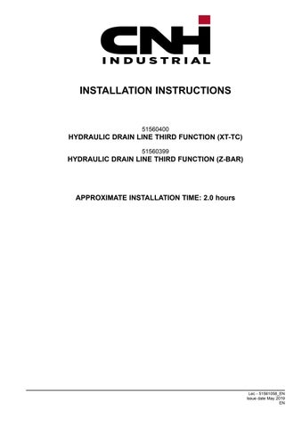
LEIL19CWL0278F A 1 Kit Installation Overview
NOTE: For a better visualization the kit installation, the following figures depict machine views with several components not shown. the hydraulic tank (A) , remove the cap from the bottom side the T- fitting (B) .
Install the drain hose (1) the bottom side the T- fitting (B) .
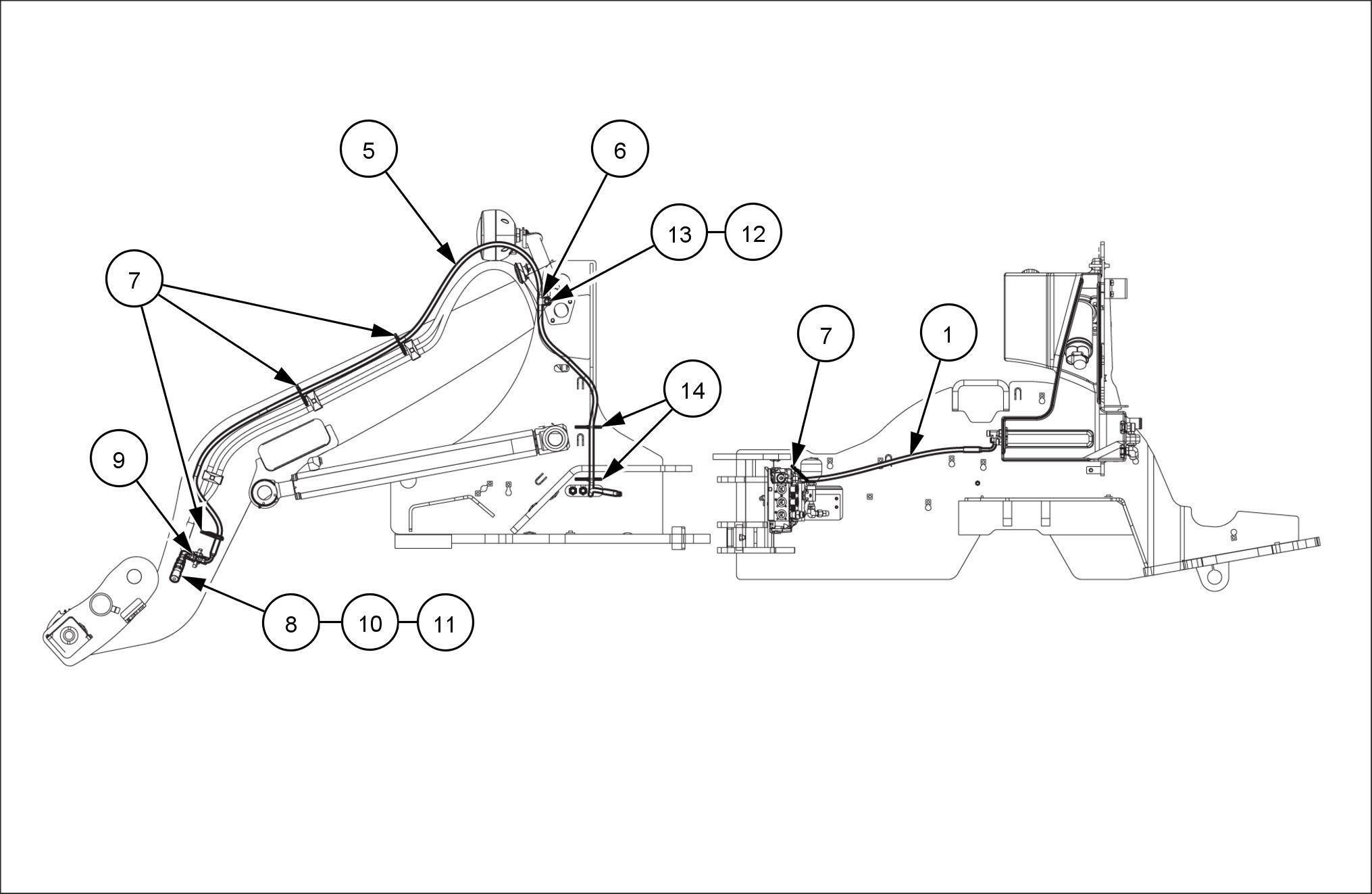
Adjust the orientation the drain hose (1) shown in
Figure 3. Tighten N·m ( ).

LEIL19CWL0282AA 2
LEIL19CWL0280AA 3
Route the drain hose (1) towards the front side the machine.
Secure the drain hose (1) the rear frame. Use the cable tie (7) . NOTE: Align the cable tie (7) the mark (1a) the drain hose (1) .

LEIL19CWL0287AA 4
Route the drain hose (1) backwards the main control valve (C) .

LEIL19CWL0301AA 5
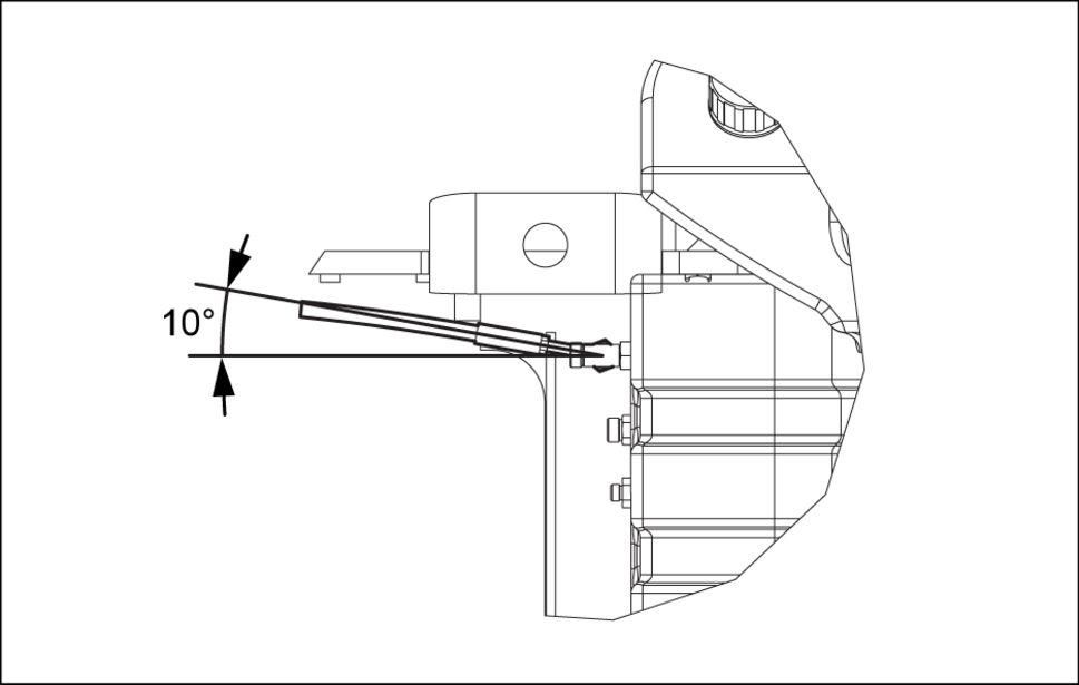
the rear frame locate the clamps (E) . Remove the hardware (H) and loosen the bolt (G) move the plate (F) and facilitate the drain hose installation.
Secure the drain hose (1) the rear frame. Use the clamp (2) , the bolt (4) , the washer (3) , and the nut (D) . NOTE: Align the clamp (2) the mark the drain hose (1) .
10. Pass the drain hose (1) through the clamps (E) shown. NOTE: Align the mark (1b) the drain hose (1) the clamps (E) .
1 Reinstall the hardware (H) reassemble the clamps (E) and the plate (F) . Tighten the bolt (G) .
LEIL19CWL0332AA 6

LEIL19CWL0284AA 7

LEIL19CWL0333AA 8

LEIL19CWL0334AA 9
12. Route the drain hose (1) towards the front side the machine. 13. Install the drain hose (5) the drain hose (1) . Tighten
N·m ( ).
14. Route the drain hose (5) towards the right - hand side the machine. 15. Pass the drain hose (5) through the hole the front frame. 16. Route the drain hose (5) upwards, next the existing hydraulic hoses (L) . 17. Secure the drain hose (5) the existing hydraulic hoses (L) . Use the cable ties (14) .
18. Secure the drain hose (5) the front frame. Use the clamp (6) , the bolt (M) , the washer (12) , and the nut (13) . NOTE: Align the clamp (6) the mark the drain hose (5) . 19. Route the drain hose (5) towards the internal side the arm.

LEIL19CWL0285AA 10

LEIL19CWL0267AA 11

LEIL19CWL0269AA 12