CLflRK
PM
Check the battery discharge indicator (if so equipped). With the battery connected and key (if equipped) in the ON position, the indicator needle should point to the green area. If not, it should be indicated on the PM report form.
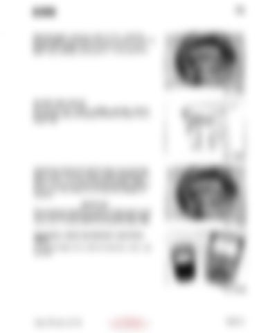
Fig. 12989 BATTERY AND CABLES After the test drive, perform a battery load test. Remove the hydraulic cover and bypass the lift limit switch with a jumper wire.
1 Fig. 25556 Operate the hydraulic lift until the forks are in maximum height position and the hydraulic system operates in the bypass mode. The battery discharge indicator needle should not drop into the red area. If the needle points to the red area, the battery is not sufficiently charged for operation. I
IMPORTANT
Do not operate the hydraulic system in the bypass mode with the lift limit switch bypassed any longer than necessary to take a reading. Remove the bypass jumper wire.
Fig. 12989
ELECTRICAL TESTS AND PERIODIC ELECTRICAL TESTS Do electrical tests with a volt-ohmmeter and a shunt type ammeter.
Fig. A0959
Code: PM-541, JAN 86
Copyrighted Material Intended for CLARK dealers only Do not sell or distribute
Page 2.5
