7 minute read
7.2 Hydraulic System


SECTION 7 – SERVICE
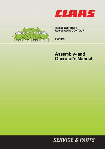
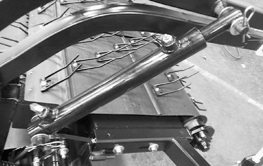
P00386
Mounted Header Brace
7.2 HYDRAULIC SYSTEM
CAUTION: High-pressure
hydraulic oil can cause serious injuries such as burns, cuts, and tissue damage! Always take precautions when working with hydraulic oil. Wear safety goggles, gloves and thick clothing. Seek immediate medical attention if cut or burnt.
A) Hydraulic Motor Installation/Removal
Removal:
a) Lower the pickup to the ground shut off combine and remove key.
b) Remove the two hydraulic lines from the motor if the motor is being replaced or repaired. Use a bucket to catch escaping oil.
c) Remove all shields that will interfere with this procedure.
d) Loosen the setscrew on the motor coupler.
e) Extract the two flange head bolts until they contact the motor. f) Proceed to extract the bolts one revolution at a time until the motor is removed.
g) Remove the two flange head bolts and place aside.
h) Remove the two 1/4" hex head bolts and thread them into the previously removed flange head boltholes until they contact the hub.
i) Rotate each bolt one revolution at a time until the hub releases.
j) Remove the coupler and hub and / or pulley.
Installation:
a) Install the coupler with hub or pulley onto the roller shaft. Be sure the coupler bottoms out with the end of the roller shaft.
b) Lock into place with the 1/4" bolts and lock washers. When tightening the 1/4" bolts, alternate several times from one bolt to the other, until both bolts are equally secure.
Return the 1/4" flange head bolts to their original location.
c) Install the hydraulic motor with key into the hydraulic motor coupler and lock into place with the setscrews.
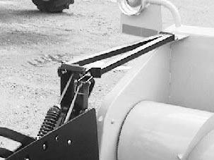
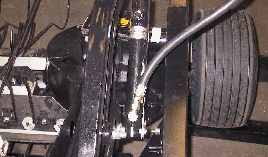
P00209
Hydraulic Motor & Torque Arm (MEGA)
37
SECTION 7 – SERVICE
B) Hydraulic Cylinder(s) Replacement
The holddown employs a single-acting master and slave circuit for raising and lowering the holddown. The operation of the lift can be adversely affected by factors such as air in the system. It is suggested that the following procedure be used to ensure proper operation of the holddown when servicing the unit.
Removal/Installation Procedure
a) Lower the holddown completely down, shut off combine and remove key.
b) Release all hydraulic pressure in the system.
c) Remove all hydraulic hoses from the cylinder(s) being removed. Be sure to have a container and rags to catch any escaping hydraulic oil.
d) Remove the two hitch pins and washers that hold the cylinder on the pickup.
e) With the help of a second individual who is slightly lifting up the holddown, pull off the cylinder and install the new one.
NOTE: There should be a washer on both sides of the cylinder.
f) Install the washers and hitch pins.
g) Complete Fitting Transfer/Installation if replacing cylinder.
Master Cylinder
a) Remove the two 90-degree elbows and the orifice from the old master cylinder.
b) Screw the orifice into the lower port of the master cylinder. Turn until the orifice bottoms out. Screw one ORB/JIC 90 degree elbow into the lower port of the master cylinder` until you feel a slight resistance then stop. Orient the elbow tip upward approximately 30 degrees to the left and tighten the jam nut.
c) Screw in the second ORB/JIC elbow into the upper port of the master cylinder until you feel a slight resistance then stop. Orient the tip of the elbow upwards parallel with the cylinder rod and tighten the jam nut. See illustration.
d) Connect the holddown hose to the upper 90degree elbow on the master cylinder. When tightening the hose ensure the hose goes up from the elbow and does not fall to the side.
e) Connect the header hose to the lower 90degree fitting on the master cylinder.
NOTE: Always use two wrenches to prevent hose twist or damage the hydraulic fittings or components.
Master Cylinder Assembly
P00317 P00303
38
SECTION 7 – SERVICE
Slave Cylinder
a) Remove the 90-degree elbow and bleed plug from the slave cylinder.
b) Screw in the ORB bleed plug into the upper port of the slave cylinder. Tighten snug.
c) Screw in the 90-degree ORB/JIC elbow into the lower port of the slave cylinder until you feel a slight resistance then stop. Orient elbow tip upward and approximately 30 degrees to the right and tighten the jam nut.
d) Connect the holddown hose to the lower 90degree elbow on the slave cylinder.
P00316
Slave Cylinder Assembly
Fitting Orientation
NOTE: Testing is required after any servicing is done to the holddown hydraulic system Refer to Testing Hydraulic Holddown procedure. C) Hose Routing and Clamping
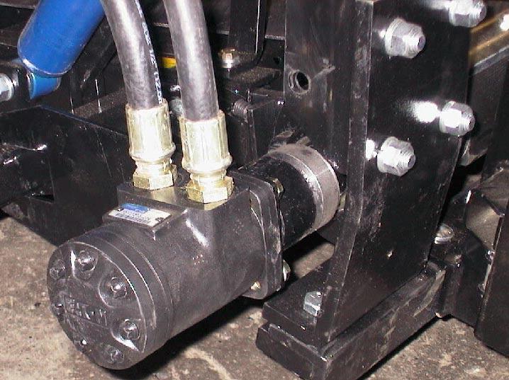
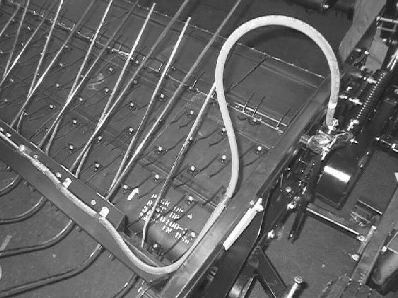
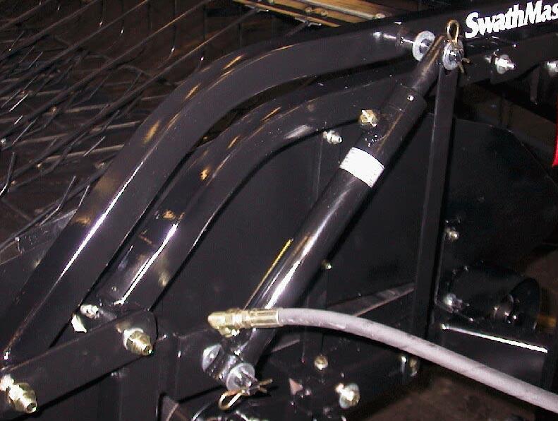
• Holddown hoses/steel lines between the cylinders that run over and across the holddown tube require proper clamping and routing to avoid hose damage.
P00315
Properly Routed Holddown Hose
• The hoses from the hydraulic motor and cylinder running to the header also require proper clamping and orientation
D) Pickup to Header Hydraulic Connections
Mega models:
The pickup is driven hydraulically by a header power pack. The drive shaft must be connected from the right hand side of the feeder house to the power pack. Hold down
P00022 Connect to Feeder House
Motor Supply
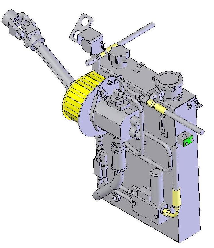
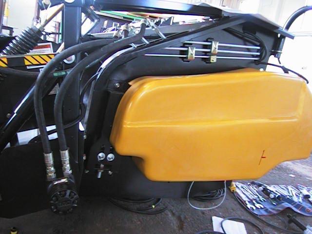
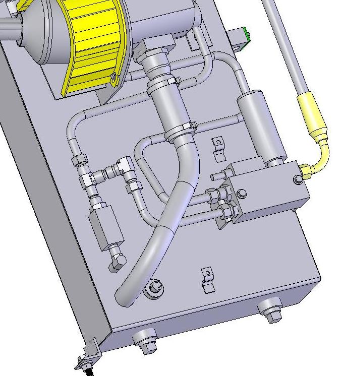
Hydraulic Power Pack
39
Motor Return
SECTION 7 – SERVICE
Maintenance and service information (Refer to illustrations):
1) Check oil level in the tank through the sight glass. Oil level should be approximately at the middle of the glass.
Breather
Filter Well
Sight Glass 4) Hydraulic power pack is equipped with a temperature sensor. If oil temperature exceeds 90oC an alarm will sound and unit must be shut down to allow fluid to cool.
Lexion models:
The pickup motor hoses connect to the steel lines secured to the header sidewall.
NOTE: The hose on the motor port closest to the header is the supply line and the hose furthest from the header is the return line. Identification of the header lines is as follows:
Lower 3/8 inch line is the hydraulic
hold down line
Middle line is the motor return line Upper line is the supply line
NOTE: Hold down hose must have sufficient slack and be oriented properly to prevent damage.
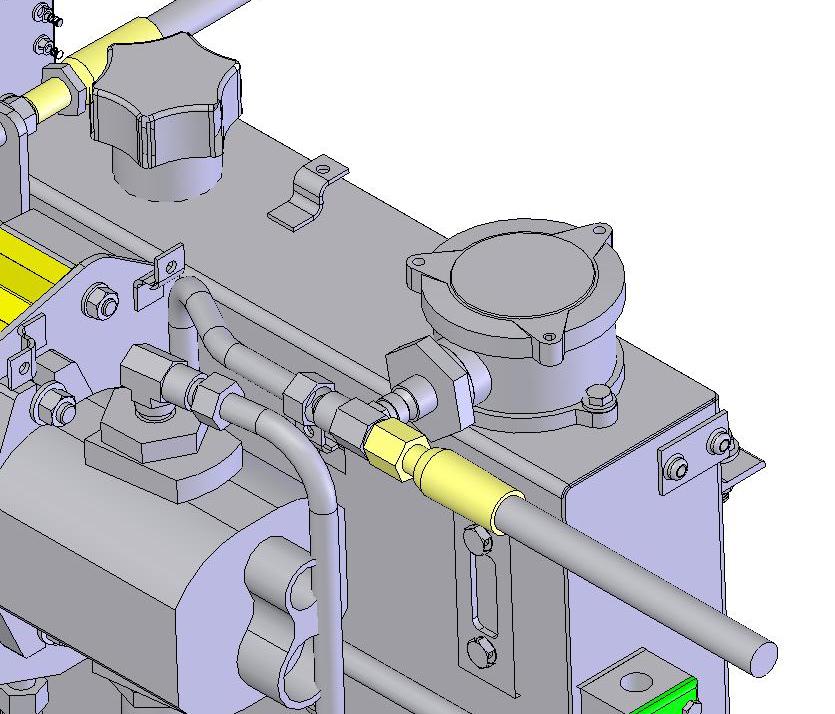
2) To replace filter element, remove the three bolts from the filter well, remove and replace element. Replace well cap and bolts.
3) Change oil when it becomes discolored and contaminated. To drain, remove plug in the bottom of the tank. To add oil, remove breather cover. Use Claas Select Agrihyd
HVLP-D (ISO VG 46) hydraulic oil.
Return
Hold down Supply
Supply Return
Drain Plugs Temperature Sensor
a) All steel lines are firmly mounted to the header wall with clamps.
40
SECTION 7 – SERVICE
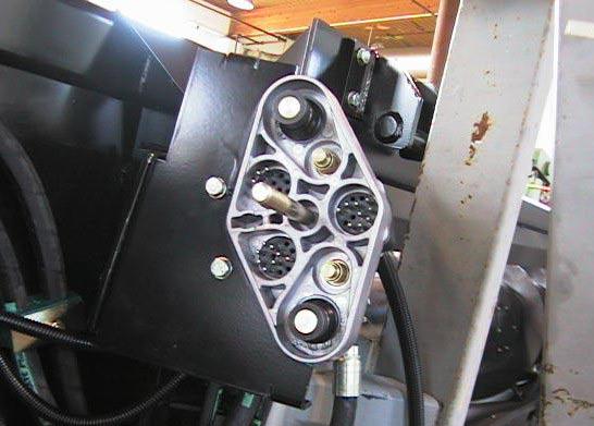
Hose Clamping
Hydraulic/Electrical Connection
NOTE: When connecting/disconnecting hydraulic fittings two wrenches should be used.
Return Supply
E) Bleeding the Hydraulics
In order for the hydraulics to perform properly, all or most of the air must be removed from the system. The following procedure provides the easiest method of bleeding the hydraulics. The hydraulics should be bled after initial installation, if the unit has sat for a significant period of time, and if adjustments are needed to the hydraulics.
CAUTION: High-pressure
hydraulic oil can cause serious injuries such as burns, cuts, and tissue damage! Always take precautions when working with hydraulic oil. Wear safety goggles, gloves and thick clothing. Seek immediate medical attention if cut or burnt.
a) The hold down is controlled using the reel lift control located in the combine cab. Fully raise the holddown.
b) Engage the holddown safety locks. Ensure that the lock is fully rotated over center so that it will not slip forward.
c) Lower the holddown so that it comes to rest on the safety locks. (This serves to relieve the hydraulic pressure in the lines).
d) Hold the plastic pail so the lip of the pail is underneath the bleed plug and so that a stream of oil shooting out of the plug will go into the pail.
e) Loosen the small bleed screw on the end of the bleed plug with a 1/4-inch wrench.
f) Have someone activate the hydraulics. The holddown may lift slightly and a stream of oil will come from the bleed screw.
g) Run oil from the bleed screw until it is a steady clear stream. Have the operator stop activating the hydraulics and tighten the 1/4inch bleed screw.
h) Fully raise the holddown again.
i) Disengage the safety locks.
j) Lower the holddown.
P00196
Slave Cylinder (RH Side)
41