4 minute read
7.9 Replacing Small Gear Box (RakeUp


SECTION 7 – SERVICE
7.9 SMALL GEAR BOX REPLACEMENT
DANGER: Lower header to the ground or engage feeder house locks, shut-off combine, remove ignition key, and wait for parts to stop moving before performing this procedure.
NOTE: Replacing the small gearbox requires a Special Gearbox Puller. (Part # 0561 225.0). Failure to use this specific tool during installation could damage the gearbox. The Special Gearbox Puller tool is available from your dealer.
D00044
1. Drive End Rotor 2. Bushing 3. Small Gearbox 4. ¼ x ¼ x 13/16 Inch Key 5. ¼ x ¼ x 1¼ Inch Key 6. 3/8 x 1 ½ Inch Bolt 8. 3/8 Inch Lock Nut 9. 7/8 Jam Nut 10. Bearing 11. Follower Arm 12. Shoulder Bolt Assembly
48
SECTION 7 – SERVICE
Removal Procedure:
a) Raise the Holddown and engage holddown safety locks.
b) Lower header/pickup completely to ground, shut of combine and remove key.
c) Remove the four 5/16 inch x 3/4-inch bolts securing drive belt shield and place shield aside.
d) Remove the drive belt.
e) Detach the scroll plate guard by removing the 1/4-inch x 1/2-inch bolts, and washers.
f) Remove the 5/16-inch x 1-inch bolts and washers securing the finger bar to the idler and drive arms. Place the finger bar aside.
g) Remove the plug in the scroll plate.
h) Rotate the main gearbox pulley until the shoulder bolt is centered in the small hole in the scroll plate.
i) Remove the shoulder bolt, two bearings, flat washer, lock washer and nut from the follower arm.
j) Remove the 3/8-inch x 1 1/2 inch bolt and nut clamping the follower arm to the small gearbox shaft.
WARNING: Always use heat
protective gloves to prevent burns to your hands when handling hot materials. Remove all combustible materials from the vicinity of an open flame. Have a fire extinguisher ready.
k) Rotate the drive rotor so that the shaft of the gearbox being removed is centered in the large scroll plate hole.
l) Heat the small gearbox jam nut with a propane torch until a yellow flame appears.
This will indicate that the permanent threadlocking compound is burned out.
m) Remove the 7/8-inch jam nut securing the small gearbox to the drive end rotor.
n) Drive the small gearbox and finger bar drive arm out of the drive end rotor. The follower arm and key will also release. Be careful not to damage the drive rotor bearings.
o) Inspect the bearings in the drive end rotor for damage or wear. Replace if necessary.
p) Heat the 7/8-inch jam nut securing the finger bar arm to the gearbox until a yellow flame appears. This will indicate that the permanent thread-locking compound is burned out.
Remove the nut.
q) Remove the 3/8-inch x 1 1/2 inch bolt and detach the finger bar arm from the small gearbox. Be sure not to lose the key.
Installation Procedure:
a) Place the finger bar arm on the short shaft of the new gearbox.
b) Reinstall the key, 3/8 UNC x 1 1/2 inch bolt and nut into the finger bar arm. Do not tighten the bolt.
c) Apply permanent thread locking compound and tighten the 7/8-inch jam nut securing the finger bar idler arm to the gearbox.
d) Tighten the 3/8 UNC X 1 1/2 inch bolt.
49
SECTION 7 – SERVICE
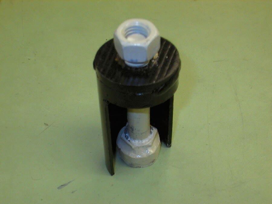
e) Rotate the drive end rotor until the gear box nest is visible through the half circle hole in the scroll plate.
f) Place the longer shaft of the gearbox through the drive end rotor and attach the special gearbox puller to the shaft.
NOTE: DO NOT pull the shaft through completely or the follower arm can not be installed.
ATTENTION: Attempting to drive the gearbox out for arm installation may result in gearbox damage.
g) Pull the shaft approximately 1 inch in.
Remove the puller.
h) Install the follower arm and key onto the shaft of the small gearbox. Orient the follower arm offset toward the scroll plate.
i) Apply permanent thread locking compound and tighten the 7/8-inch jam nut. The 7/8inch jam nut will pull the gearbox into its permanent position.
j) Install and tighten the 3/8-inch x 1 1/2 inch bolt and lock nut on the follower arm.
k) Rotate the drive end rotor until the follower arm on the new gearbox is centered in the small hole in the scroll plate.
l) Install the flat washer, two bearings, shoulder bolt, lock washer and nut to the follower arm.
See drawing for proper orientation.
m) Install the scroll plate plug.
n) Install the finger bar and apply permanent thread locking compound to the 5/16-inch x 1-inch bolts that are used to secure the finger bar to the finger bar idler arm. Snug the bolts to the finger bar arms. o) Rotate by hand the drive end rotor one complete revolution. This is to ensure that the finger bars are seated properly.
p) Tighten the four remaining finger arm bolts.
q) Install the scroll plate guard.
r) Install the drive belt.
s) Install the drive belt guard.
t) Check gearbox lubrication level. Add Mobilux EP023 gear lube as required.
NOTE: Occasionally during installation of the gearboxes, the gears may bind. However, after the 7/8-inch jam nuts have been tightened, the gearbox will operate correctly.
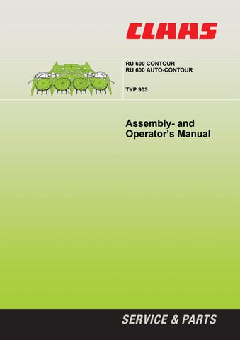
Special Tool Gearbox Puller
Puller on Gearbox
P00081
P00082
50