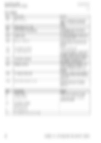
09 Hydraulic system 0980 Hydraulic circuit diagram 655-002
Key to diagram Item
Component
Remark
2015
Hydraulic pump
Version a) Fixed-displacement pump Version b) Variable load-sensing pump
4007
Orifice plate G Ø 1.0 mm
1.0 mm
4054
Power beyond mode restrictor
Only installed with power-beyond mode if necessary
6034
System screw
For blocking the pressure balance in power beyond mode
7006
Pressure relief valve
Limits the oil pressure of the tractor hydraulic system, 220 bar max. are allowed
7063
Input pressure balance
Spring 15 bar pre-load
7068
LS signal shuttle valve
Transmits the highest LS signal to the input pressure balance (7063) or to the tractor hydraulic pump (version b)
7072
Volume flow controller
In the example of version b), this is set to 20 bar on the LS pump
7073
Pressure controller
Limits the maximum pressure of the tractor hydraulic pump. In the example of version b), this is set to 220 bar
7085
LS pressure relief valve
Limits the LS pressure and therefore the working pressure of the baler and UNIWRAP
7104
Volume flow controller (red A)
Controls the flow rate to the baler hydraulic valve block. Example of version a)
Item
Component
Remark
a)
Tractor version 1
Tractor with constant-flow system
b)
Tractor version 2
Tractor with LS pump and power beyond connection
LS -
Load pressure signal
-
T
Return line (tank)
-
P
Oil supply (pump)
-
Ps
Oil supply (downstream of oil filter)
-
56
00 0290 114 4 - SYS Rollant 455 / 454 UNIWRAP - 09/2014
