1 minute read
Fitting the hydraulic lines

from CLAAS DISCO 9300 C Duo DISCO 9300 RC Duo DISCO 8600 C Duo Assembly and conversion instructions Manua

5
4
Advertisement
3
1 32
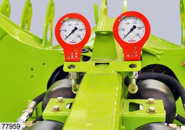
• Fit gauges(1) and(2) on holder(6) with contact washers(5) and hexagon nuts(4).
(Fig.31,32)
• Attach and tighten hoses(3) to gauges(1) and(2). (Fig.33)
4 A16 (1x)
5 M16x1.5 (1x)
33
Fitting the hydraulic lines
• Remove cover(1). (Fig.34)
2
3 P2
LS 34
Frame, left
Remove hydraulic hoses(P2) and(LS) from the frame: • Remove covers(2) and(3). (Fig.35)
35
2 3 4
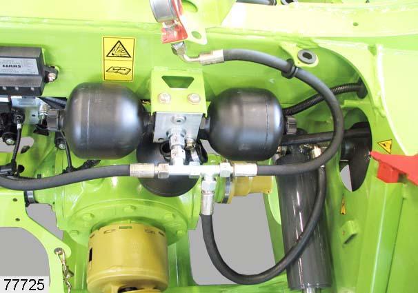
• Attach clamps(2) and(3) to the pressure accumulator block(4). • Pull hydraulic hoses(P2) and(LS) into the frame. (Fig.36)
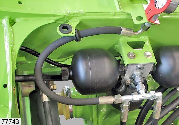
5 T 36
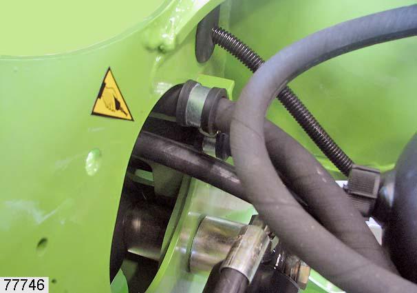
• Remove lever(6) from shut-off cock(5) on hose(T). (Fig.37,38)
6
5 T 37
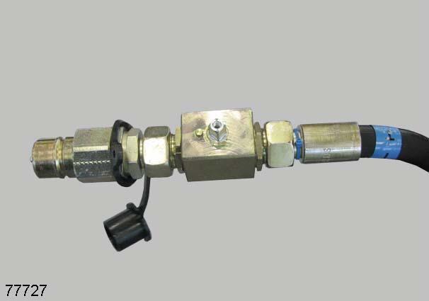
T
P1 7
8 38
Frame, right
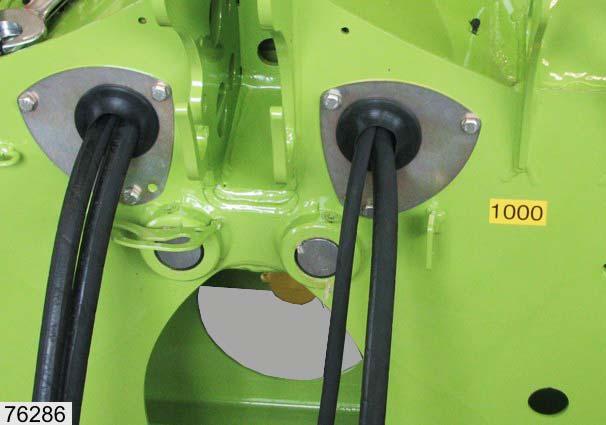
Removing hoses(T) and(P1) from frame: • Remove covers(7) and(8). (Fig.39)
39
4
7 8
P1
T
9
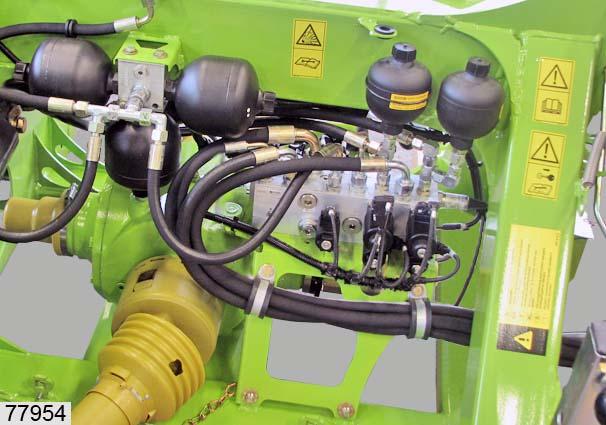
• Attach clamps(7) and(8) to the pressure accumulator block(4). • Pull hydraulic hoses(T) and(P1) into the frame. (Fig.40)
Frame, left
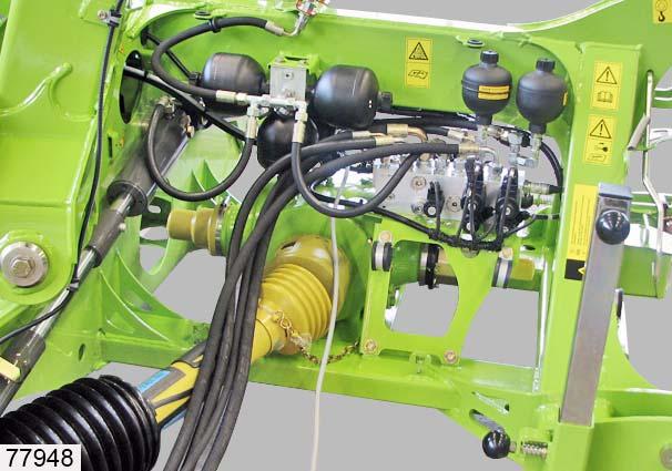
• Pull hydraulic hoses(T) and(P1) to the left side of the frame. Hydraulic hoses(LS), (T), (P1) and(P1) are now loose on the left side of the frame. (Fig.41)
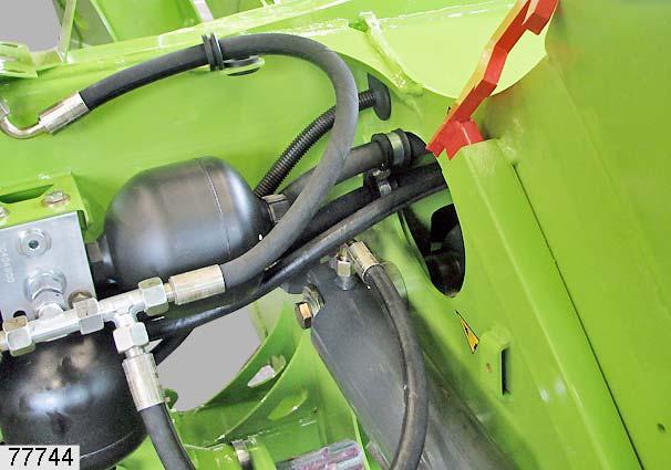
• Bend hydraulic hoses(LS), (T), (P1) and(P1) around to the rear. • Fix hydraulic hoses(LS), (T), (P1) and(P1) to the support using the existing clamps(9). (Fig.42)
40
41
42
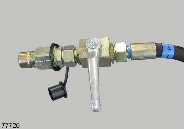
X 5 T
• On hose(T) mount lever(3) on shut-off cock(2). • Smear screw(X) with Loctite before tightening. (Fig.43,44)
5 T 43
6