2 minute read
Hydraulic system .............................................................. 6


5 General preparation
The DISCO 8700CPlus/ 8700C mower unit is intended for operation with the JAGUAR Model 492 and Model 491. The following measures must be carried out on the JAGUAR before fitting the DISCO 8700 C Plus/ 8700C.
HYDRAULIC SYSTEM
The supplied double-acting lifting cylinders must be fitted to the JAGUAR. JAGUAR Model 492: –see Hydraulic system, page6.12 JAGUAR Model 491: –see Hydraulic system, page6.26.
TYRES
Only radial tyres are permissible at the front; water-filled tyres must be used at the rear.
ADDITIONAL WEIGHTS
Additional weights must be fitted to the JAGUAR to ensure adequate loading of the rear axle.
JAGUAR Model 491:
JAGUAR 820 with four-wheel drive: 13 additional weights JAGUAR 820 without four-wheel drive: 14 additional weights JAGUAR 840, 860, 880 with four-wheel drive: 12 additional weights JAGUAR 840, 860, 880 without four-wheel drive: 13 additional weights
with four-wheel drive: 13 additional weights without four-wheel drive: 14 additional weights
with four-wheel drive: 12 additional weights without four-wheel drive: 13 additional weights
with four-wheel drive: 10 additional weights without four-wheel drive: 11 additional weights
JAGUAR Model 491 Overdrive:
JAGUAR Model 492 (40 km/h):
JAGUAR Model 492 (20 km/h):
S
E 1
Ordering numbers: 4 additional weights 450 kg S09 0030 7 additional weights 630 kg S09 0045 12 additional weights 1332 kg S09 0080
LIGHTING
When driving on the road the headlamps are partially covered, with the result that additional headlamps are required on the cabin. Furthermore, additional flashing lights must be fitted at the sides.
Order number
Upper headlamps and flashing lights Q03 0020
REMOVING THE FEEDER HOUSING
Danger!
Only undertake work on the feeder housing when the drive is switched off and the engine is at a standstill. –Remove the ignition key!
Remove the feeder housing with the front attachment still attached.
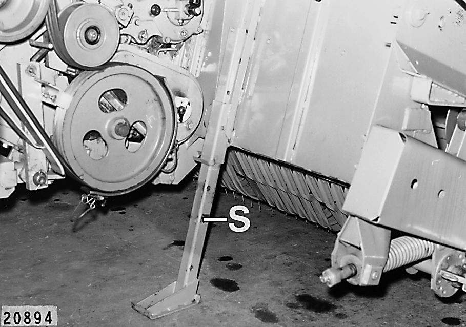
1.Lower the front attachment to the ground.
Lower the supports(S) on both sides until they touch the ground, and secure. (Fig.1)
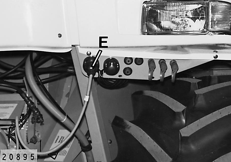
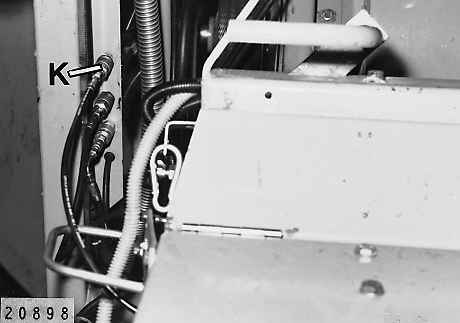
2.On the left hand side, pull out the plug(E) for the metal detector. (Fig.2)
2
Z
A
D
H
K G
O
R S
F
P 3
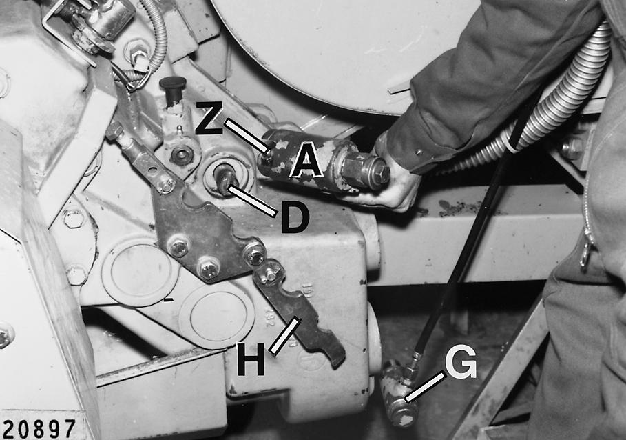
3.On the left hand side, undo and fold up the bracket(H) for fastening the hydraulic cylinder.
Remove the hydraulic cylinder(G) for group shifting (if present).
Lift hydraulic cylinder(A) out until ball stud(Z) slides out of the guide on the shifter rail(D).
Lay the flexible hose and hydraulic cylinder securely on the operator's platform. (Fig.3)
Machine with central lubrication system: 4.On the right hand side, disconnect the quick release coupling from the central lubrication system. (Fig.4)
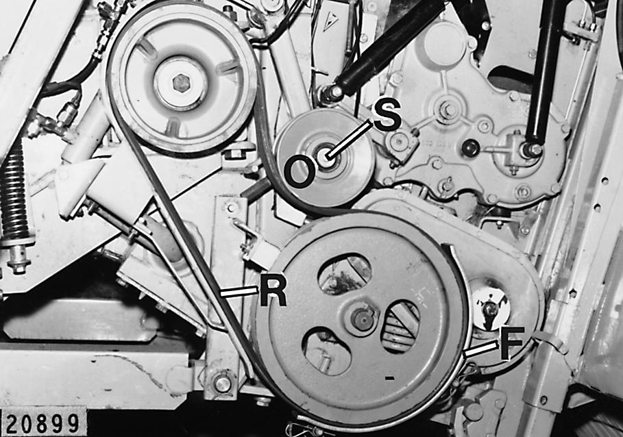
5.Unscrew the hexagon head bolt(S) axially fastening the idler pulley (O) and remove the idler pulley. 6.Release and remove the guide bracket(F).
Remove the banded V-belt (R) from the lower belt pulley. (Fig.5)
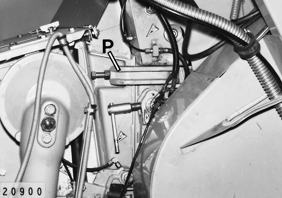
7.Loosen the clamps(P) on both sides and fold back. (Fig.6)
4
5