2 minute read
Lowering the machine in the folded condition..................................................6
from CLAAS DISCO 8550 C PLUS /8550 C DISCO 8550 PLUS / 8550 DISCO 8550 C-T Assembly and operator's manual
6
130
131
1 1

132 Note!
DISCO8550CPlus / 8550C/ 8550C-T: If the machine is at a standstill for a longer period of time, the check lamp(6) on the control terminal must be out. The electrical connection to the tractor must be interrupted. (Fig.130)
Lowering the machine in the folded condition
Danger!
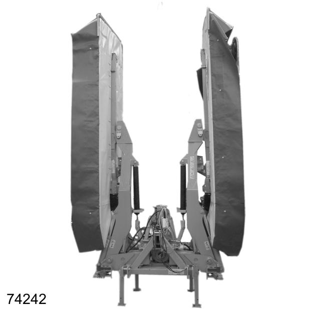
Gusts of wind and uneven or soft ground can cause the lowered machine to tip over. –Only store the machine in the folded condition in an equipment shed. (Fig.131)
DISCO8550CPlus / 8550C/ 8550C-T
• Hinge the mower unit into the transport position
• Slide the stands(1) downwards and locate in position with the pin. (Fig.132) • Lower the mower unit down to the ground using the three point linkage. • Move the single-acting control valve to the 0 position (neutral). • Push this button. The lamp lights up green. • Push both these buttons. Both lamps light up red.
3

133
6
134
• Set the single-acting control valve to the floating position. Lower the middle mower unit down to the ground. • Turn off the control system.
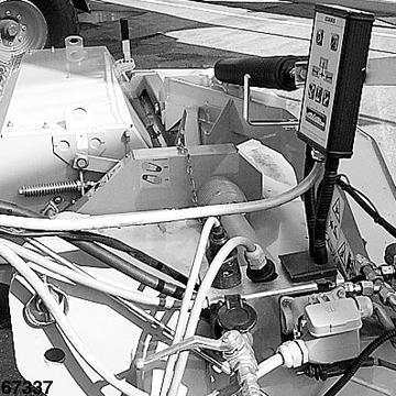
• Unhook the upper and lower links. • Uncouple the universal drive shaft and suspend on the three point stand using the chain. • Disconnect the hydraulic and electrical connections. Unplug the connector, hydraulic hose and control terminal on the hose bracket(3). Make sure that the control terminal is located vertically in the hose bracket. (Fig.133) CAUTION! Protect the control terminal from moisture! • Drive the tractor away.
Note!
If the machine is at a standstill for a longer period of time, the check lamp(6) on the control terminal must be out. The electrical connection to the tractor must be interrupted. (Fig.134)
1

DISCO8550Plus / 8550 / 8500C 1
135
3

7
136 DISCO8550Plus / 8550 / 8500C
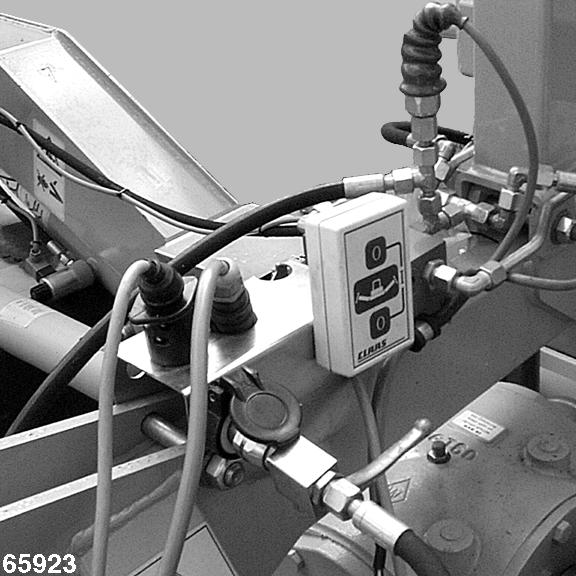
• Swing the mower unit into the transport position with the single-acting control valve. Apply pressure until the side mower units are hinged up completely and the lamps(7) on the control terminal go out. (Fig.136) • Slide the stands(1) downwards and locate in position with the pin. (Fig.135) • Lower the mower unit down to the ground using the three point linkage. • Set the single-acting control valve to the floating position. Lower the middle mower unit down to the ground. • Turn off the control system. • Unhook the upper and lower links. • Uncouple the universal drive shaft and suspend on the three point stand using the chain. • Disconnect the hydraulic and electrical connections. Unplug the connector, hydraulic hose and control terminal on the hose bracket(3). Make sure that the control terminal is located vertically in the hose bracket. (Fig.136) CAUTION! Protect the control terminal from moisture! • Drive the tractor away.
Note!
If the machine is at a standstill for a longer period of time, both check lamps(7) on the control terminal must be out. The electrical connection to the tractor must be interrupted. (Fig.136)


