2 minute read
Malfunctions............................................................................8
from CLAAS DISCO 8550 C PLUS /8550 C DISCO 8550 PLUS / 8550 DISCO 8550 C-T Assembly and operator's manual
Push back the universal drive shaft guard(S). (Fig.64)
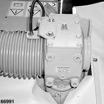
Fit sensor(1) to the gearbox with sensor bracket(2), hexagon head bolts(3) and contact washers(4). (Fig.65)
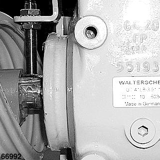
Setting the height of the sensor(1). To do this, release the hex nuts(M), move the sensor(1) in the required direction and re-tighten the hex nuts(M).
Tightening torque of the hex. nuts(M) =15Nm
The distance between the sensor(1) and a tooth on the universal drive shaft(W) should be approx. 4 mm. (Fig.66)
Then set the distance from the sensor(1) to the carrier bracket(A) of the universal drive shaft. This is done by displacing the sensor bracket(2) in the slotted holes. (Fig.67,68) The distance between the sensor(1) and the slip-on coupling(A) should be 2-4 mm. (Fig.67)

S
1
2
M
1
4 mm
W
1
2-4 mm 64
66 65
67
S
O L 2
T 5 68

5 10 1
7
7 10 5
The universal drive shaft guard(S) should be cut to suit and be pushed back in position.

Caution!
Note the position of the lubrication points(O)!
(Fig.68)
Fit sensor(1) to the gearbox with clamp(5) and bolt(T). (Fig.69)
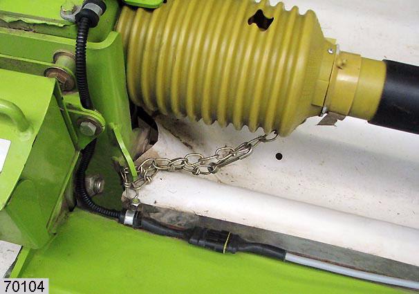
Plug the connector of sensor(1) into the connector of cable(7). Fit the cable of sensor(1) with clamp(5) and contact washer(10). (Fig.70)
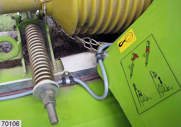
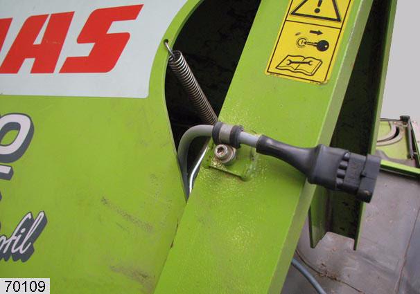
Route the cable(7) towards the rear. Fit cable(7) with clamps(5) and contact washers(10). (Fig.71-75)
69
70
71
7 5 10
9 14 11 9 12 14 13
7
Make sure that the cable forms a slight loop on the fitting frame (see arrow). Fit cable(7) with clamp(9), hexagon head bolt(12), serrated lock washer(14) and self-locking nut(13). (Fig.72)

Fit cable(7) with clamp(9), set screw(11), serrated lock washer(14) in the drilled holes provided. (Fig.73)
Fit cable(7) with clamp(9), set screw(11), contact washer(10) in the drilled holes provided. (Fig.73)
72
73
7

11 10 9 74
75
7
6

7

6 Note!
Lift the front mower unit and check the cable length by moving it.
Pushed combination
Plug the connector of cable(7) into the connector of cable(6). Ensure that cable(6) is long enough. It should not be pulled taut or damaged at any point in the folding process (see arrow). (Fig.76)
Towed front - rear combination
Plug the connector of cable(7) into the connector of cable(6). Plug the connector of cable(6) into the connector of cable(8). (Fig.77)
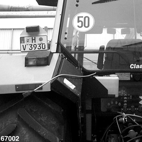
Route cable(8) back along the tractor and through the cab to the side mower units. (Fig.78)
8 76
77
8
78
1

79 Note!
If the front mower unit is not fitted with the speed monitor, switch(1) can be switched to the left or right in order to turn off the warning signal tone –see »Bridging out switch«, page7.11. (Fig.79)


