SECTION 2 – SET UP
a. b. c. d.
e.
Attach the rear of upper and lower hold down arms to the frame using the 1/2 X 3-1/2" hex head bolts, short bushings, rear plate, and hardware. Assemble side plates, bushings, flanged bushings and hardware. Leave hardware loose. Install the fiberglass rod tube to the hold down arms via the assembly from step b. Use forward most bolts on side plate assembly to attach spring wire tube to hold down arms. NOTE: Make sure the tabs on the RH end of the square tube slides between the side plate and its tab. Spring wires must be positioned over belts and between fiberglass rods. Refer to “Rotating Spring wires Out of Shipping Position” and “Fiberglass Rod/Spring wire Orientation” sections in this manual.
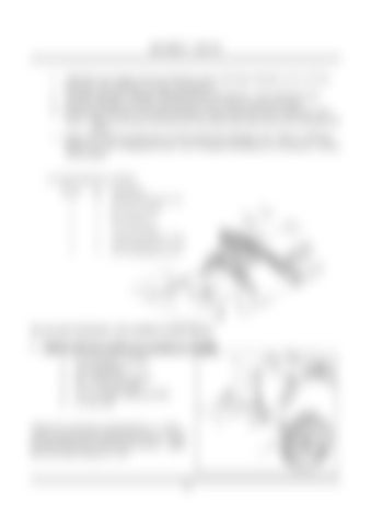
5) Install hold down cylinders. ITEM No.
QTY
1
4
5/8 SAE FLAT WASHER PLATED
DESCRIPTION
2 3
4 2
PIN, 1/8 X 2 9/16 HITCH
4
2
PIN, CLEVIS 5/8" x 5"
5
2
3/8 x 2 3/4 UNC BOLT
6
6
3/8 USS FLAT WASHER, PLATED
7
2
WSHR NEOPRENE,3/8 X 1.1 X .062
9
2
NUT, 3/8 UNITORQUE PLATED
PIN, CLEVIS 5/8" x 4"
See your parts manual for a more detailed assembly diagram. C. WHEEL INSTALLATION (up to machine no. 4324000) 1. 2. 3. 4. 5. 6.
Tire & Spindle Assembly 1/2" Flat Washer M12, Spring Lock Washer 1/2 x 1 1/2" UNC Bolt 1/2 x 6" Height Adjustment Bolt 1/2" Hex Nut
Attach tires to the frame using hardware 2, 3, and 4 with the spindle plate positioned long side up. Install the adjustment bolt (5) and Nut (6) as shown. Adjust bolt to an initial setting of 2 5/16".
10


