3 minute read
15.10 Driving speed reduction

from Caterpillar NSP 10N2R 12N2R 12N2IR 14N2R 14N2IR Lift Trucks Service, Operation & Maintenance Manual

With duplex masts with two side cylinders and triplex masts, the driving speed is reduced by 0.5 km/h after a 1,000 mm lift.
With duplex and triplex masts with free lift, the driving speed is reduced by 0.5 km/h after the free lift.
15.10.1 Driving speed reduction sensor
Type
Size
Vs
Switching output
Electrical wiring
Sensing range
Spare part Magnetic reed switch
Flat rectangular 9 mm x 13 mm x 44 mm
0 – 200 VAC/VDC
Bi-stable contact with an S actuating magnet
DC 2-wire, Vs = BRN, GND = WHT
Up to 60 mm, depending on the actuating magnet
RL609813
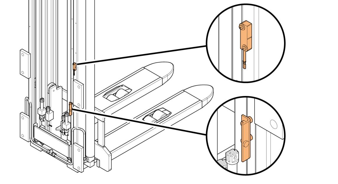
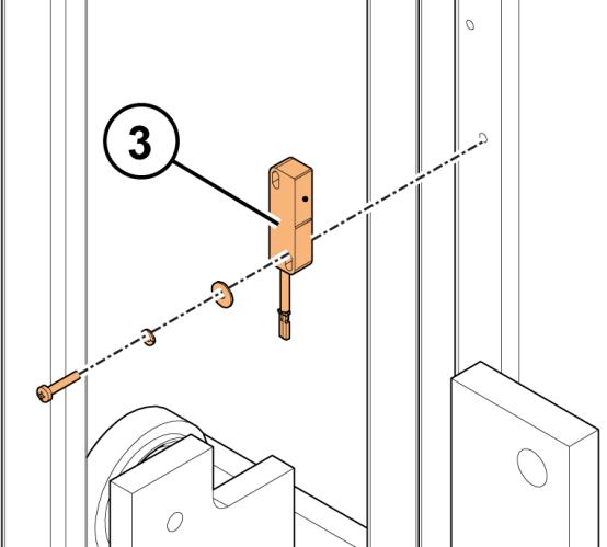
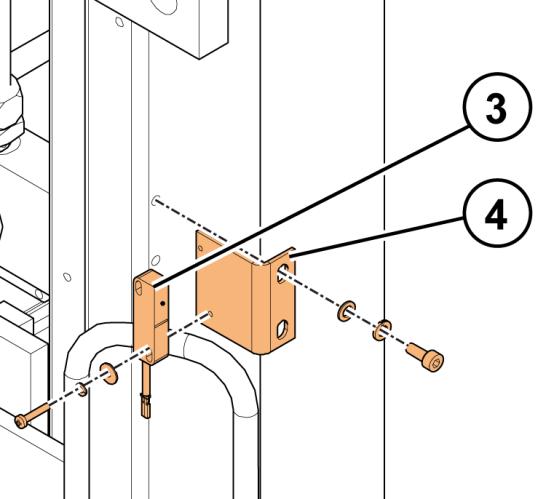
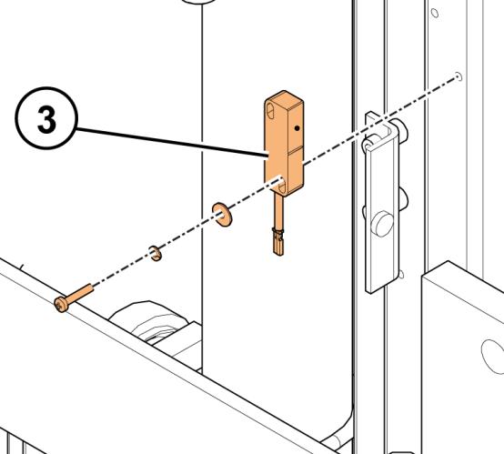
Figure 144. Driving speed reduction sensor overview (duplex mast with two side cylinders and triplex mast)
Copyright© 2013 by MCFE. All rights reserved. Revision: B Document ID: 616843 311 (338)
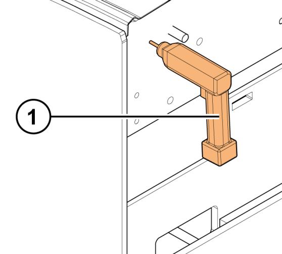
1. Drill a hole into the truck frame for the sensor wires.
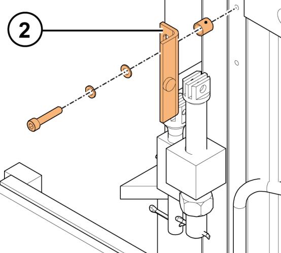
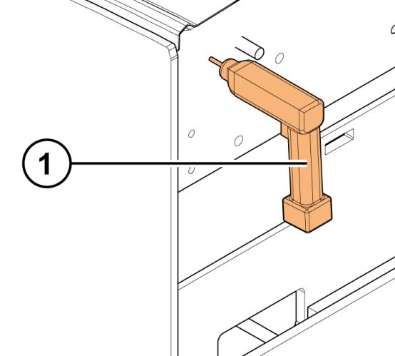
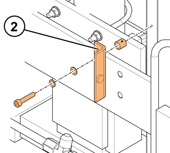
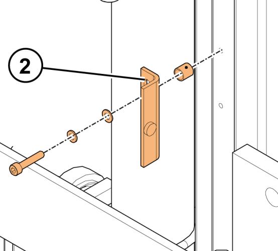
2. Screw the magnet’s mounting plate into the (first) internal mast. For the correct placement, see Figure 145.
3. Screw the sensor into the mast unit.
For the correct placement, see
Figure 145.
4. Connect the sensor wires according to the truck model specific schematic diagram. 5. Set the parameter Cutback Speed 1 to 15%.
Copyright© 2013 by MCFE. All rights reserved. Revision: B Document ID: 616843 312 (338)
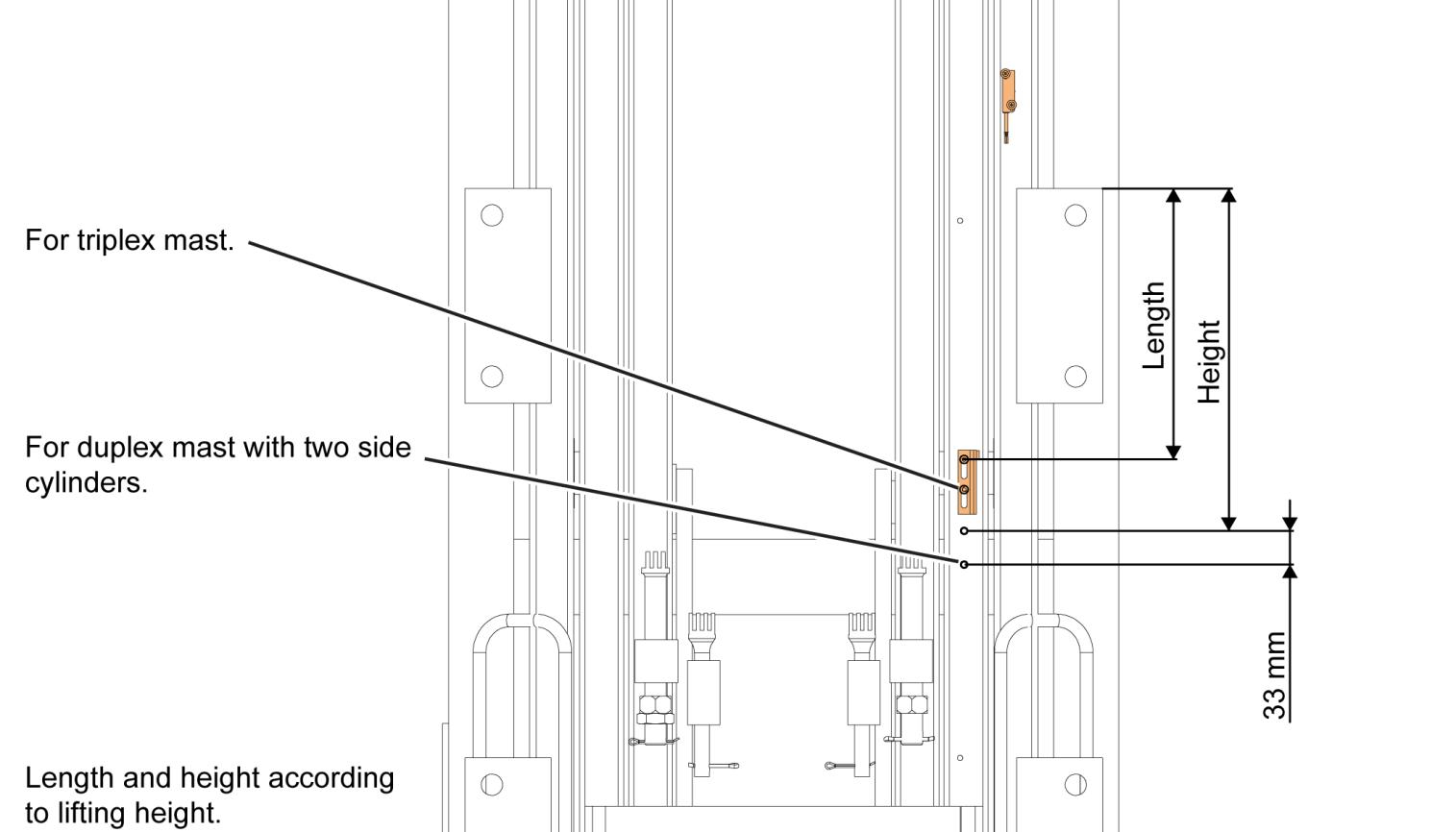
Figure 145. Correct placement of the driving speed reduction sensor (duplex mast with two side cylinders and triplex mast)

Figure 146. Driving speed reduction sensor overview (duplex mast with free lift)
Copyright© 2013 by MCFE. All rights reserved. Revision: B Document ID: 616843 313 (338)
1. Drill a hole into the truck frame for the sensor wires.
2. Screw the magnet’s mounting plate into the (first) internal mast. For the correct placement, see Figure 147.
3. Install the sensor to the mounting plate. For the correct placement, see
Figure 147. 4. Screw the sensor’s mounting plate to the main mast unit. For the correct placement, see Figure 147.
5. Connect the sensor wires according to the truck model specific schematic diagram. 6. Set the parameter Cutback Speed 1 to 15%.
Copyright© 2013 by MCFE. All rights reserved. Revision: B Document ID: 616843 314 (338)
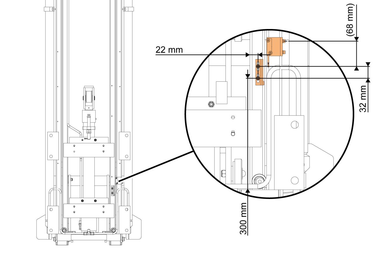
Figure 147. Correct placement of the driving speed reduction sensor (duplex mast with free lift)
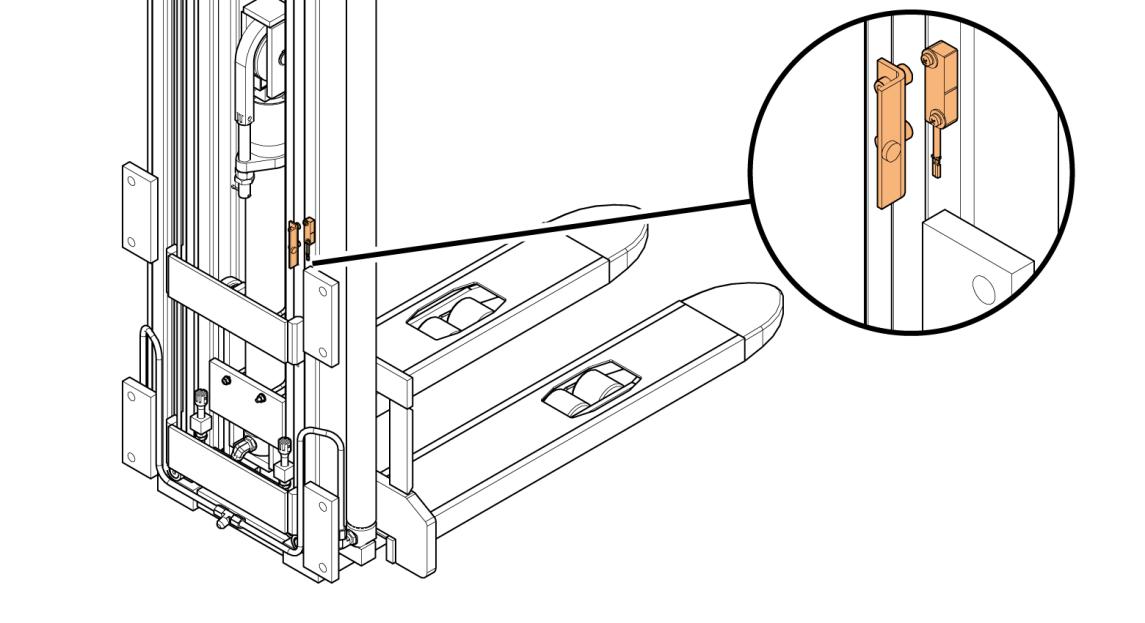
Figure 148. Driving speed reduction sensor overview (triplex mast with free lift)
Copyright© 2013 by MCFE. All rights reserved. Revision: B Document ID: 616843 315 (338)
1. Drill a hole into the truck frame for the sensor wires.
2. Screw the magnet’s mounting plate into the first internal mast. For the correct placement, see Figure 149.
3. Screw the sensor into the mast unit.
For the correct placement, see
Figure 149.
4. Connect the sensor wires according to the truck model specific schematic diagram. 5. Set the parameter Cutback Speed 1 to 15%.
Copyright© 2013 by MCFE. All rights reserved. Revision: B Document ID: 616843 316 (338)
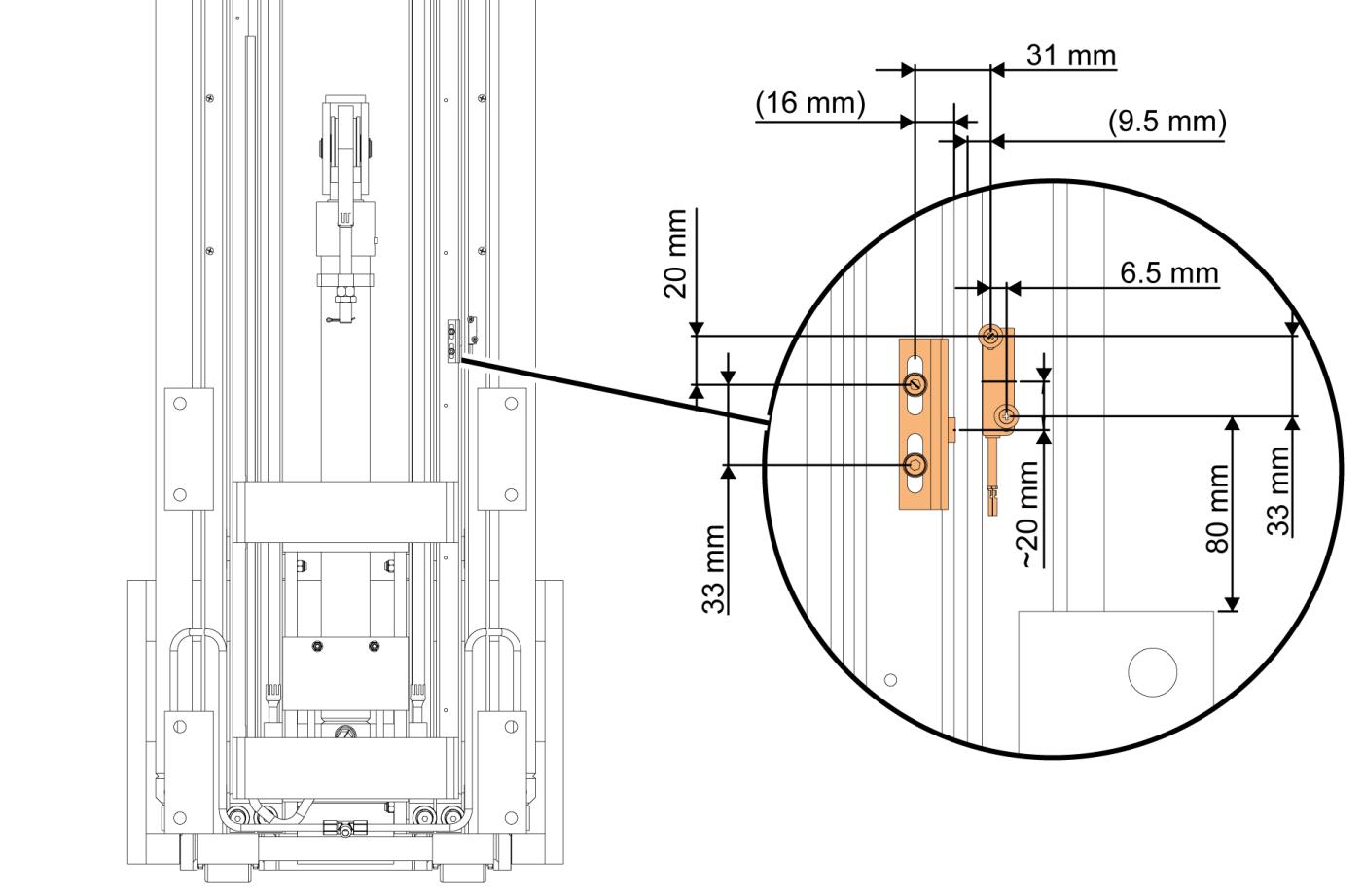
Figure 149. Correct placement of the driving speed reduction sensor (triplex mast with free lift)
Copyright© 2013 by MCFE. All rights reserved. Revision: B Document ID: 616843 317 (338)