10 minute read
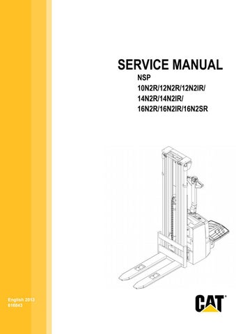
4.3 Overview of the truck

from Caterpillar NSP 10N2R 12N2R 12N2IR 14N2R 14N2IR Lift Trucks Service, Operation & Maintenance Manual

4.3.1 Operating devices
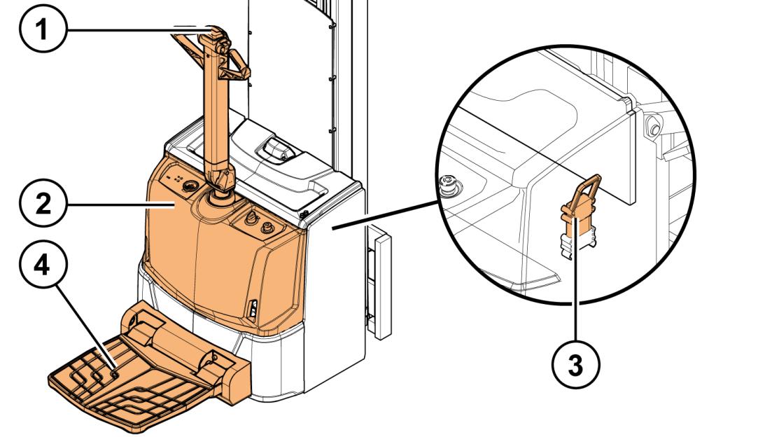
Figure 2. Operating devices
1. Tiller arm 2. Front cover with controls 3. Battery connector (under the battery cover) 4. Operator’s platform
Copyright© 2013 by MCFE. All rights reserved. Revision: B Document ID: 616843 18 (338)
4.3.2 Tiller arm
4.3.2.1 Tiller arm controls
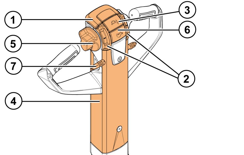
Figure 3. Tiller arm controls
1. Safety button 2. Push buttons for lifting and lowering 3. Horn 4. Steering 5. Accelerator 6. Brake release / low speed button 7. Lever for lifting and lowering
Table 1. Control functionalities
CONTROL
Safety button (belly button) The safety button prevents you from getting squeezed between the truck and an obstacle. When the safety button is pushed, the truck reverses its travelling direction. When the button is released, the truck stops.
Push buttons for lifting and lowering Push the Up button to lift the mast. Push the Down button to lower the mast. NOTE: With initial lift mast model, the push buttons handle the lowering and lifting lift of the forks and the lever lifts and lowers the mast. With other mast models, the functions of the push buttons and the lever are identical.
Horn Press the button to give an audible warning signal.
FUNCTIONALITY DESCRIPTION
Copyright© 2013 by MCFE. All rights reserved. Revision: B Document ID: 616843 19 (338)
CONTROL
Steering
Accelerator
FUNCTIONALITY DESCRIPTION
The tiller arm turns ± 100 degrees.
Use the accelerator with your right or left hand. The more you turn the accelerator, the higher the speed. The accelerator returns automatically to the central position, when it is released. Brake smoothly by turning the accelerator to the opposite direction.
Brake release / low speed button The button has two functions: • Brake release When the tiller arm is in the up position, hold the button down to release the parking brake and turn the accelerator to drive the truck in the slow speed mode. Release the button to apply the parking brake. • Low speed mode When the tiller arm is in the driving position, activate the low speed mode by pressing the button once. The Lo SPd symbol is shown in the multi-function display. Deactivate the low speed mode by pressing the button again.
Lever for lifting and lowering Pull the lever up to lift the mast. Push the lever down to lower the mast. NOTE: With initial lift mast model, the push buttons handle the lowering and lifting lift of the forks and the lever lifts and lowers the mast. With other mast models, the functionalities of the push buttons and the lever are identical.
Copyright© 2013 by MCFE. All rights reserved. Revision: B Document ID: 616843 20 (338)
4.3.2.2 Tiller arm positions
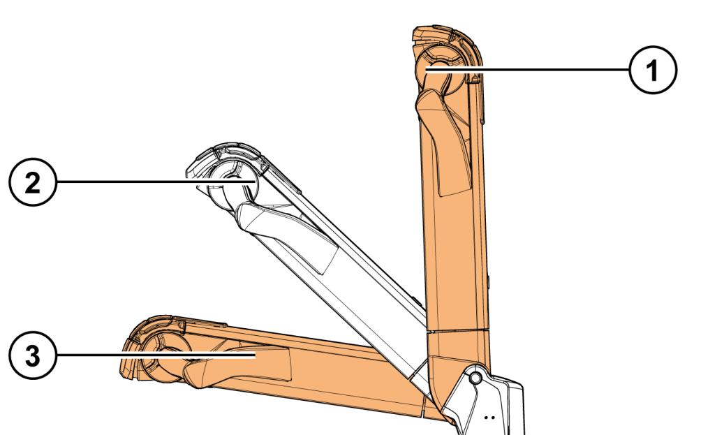
Figure 4. Tiller arm positions
1. Rest position / emergency braking 2. Driving position 3. Emergency braking
Copyright© 2013 by MCFE. All rights reserved. Revision: B Document ID: 616843 21 (338)
4.3.3 Front cover with controls
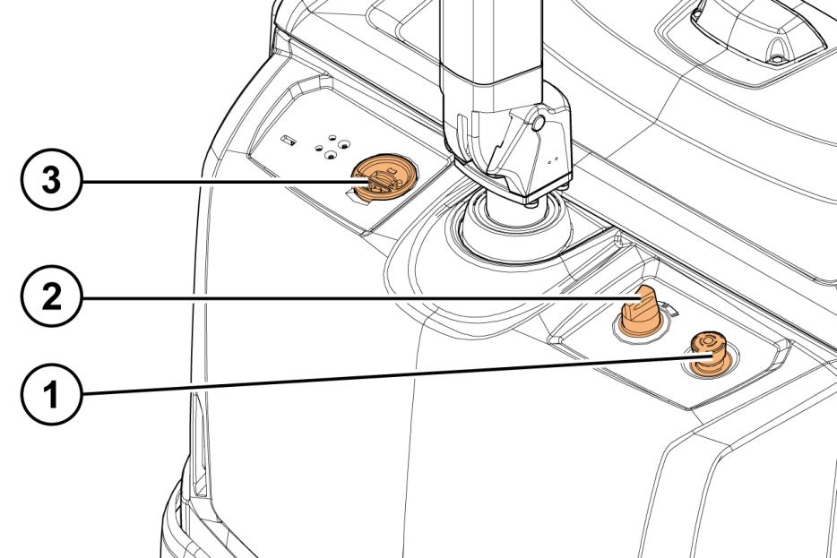
Figure 5. Front cover with controls
1. Emergency stop button 2. Key switch 3. Truck display
4.3.3.1 Emergency stop button
Press the emergency stop button to disconnect the truck's power supply. Release the button by turning it clockwise.
Use the emergency stop button in the following cases:
• In case of a short circuit or some other electrical malfunction (for example, if the pump motor does not stop running). • In case of an accident.
Copyright© 2013 by MCFE. All rights reserved. Revision: B Document ID: 616843 22 (338)
4.3.3.2 Key switch
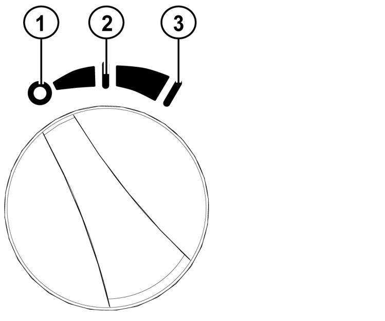
Figure 6. Key switch
1. Power off 2. Power on, economy mode 3. Power on, standard mode
The key switch switches the truck's electrical system on and off.
When the key switch is in the off position, the truck’s electrical system is turned off. Note however that power may be still connected to certain electronic devices.
When the key switch is turned once to the right, the truck’s electrical system is turned on and the economy mode (lower energy consumption and deceleration, maximum speed limited to ~5 km/h) is activated. The ECO symbol is shown in the multi-function display.
When the key switch is turned once more to the right, the standard mode (normal energy consumption and deceleration, maximum speed 6 km/h) is activated.
Copyright© 2013 by MCFE. All rights reserved. Revision: B Document ID: 616843 23 (338)
4.3.3.3 Truck display
There are two display versions available:
• LED display (standard) • Multi-function display (alternative)
LED display
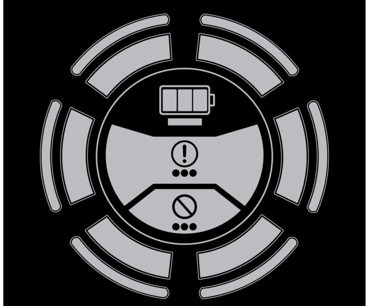
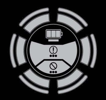
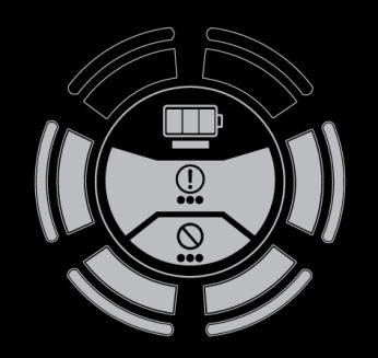
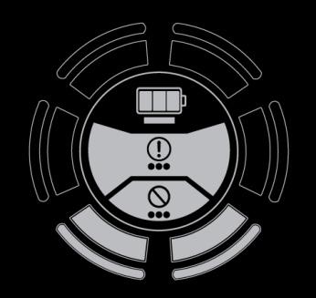
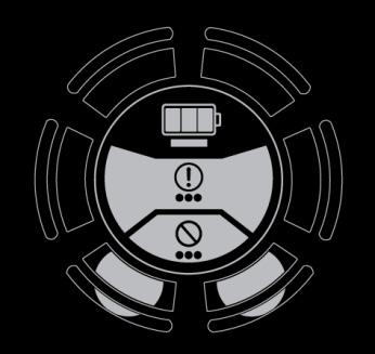
Figure 7. LED display
The LED display shows the following information:
• Level of battery charge, the different level indications are explained in Table 2 below.
• Fault indications:
Green = System OK Flashing yellow = Warning Flashing red = Error
Copyright© 2013 by MCFE. All rights reserved. Revision: B Document ID: 616843 24 (338)
Table 2. Level of battery charge indications
LED DISPLAY DESCRIPTION
Green light in all six dial segments = Battery charge level at 70 - 100%
Yellow light in the bottom four dial segments = Battery charge level at 40 - 70%
Red light in the bottom two dial segments = Battery charge level at 20 - 40%
Slowly flashing red light in the bottom two dial segments = Battery charge level at 0 - 20% (battery is empty, recharge immediately)
In case of a warning or error, press and hold down the brake release button to read the warning or error code. The LED display uses a flashing light sequence to indicate the error code as explained in Table 3.
Copyright© 2013 by MCFE. All rights reserved. Revision: B Document ID: 616843 25 (338)
Table 3. Fault indication sequence
FUNCTION DESCRIPTION
GREEN LED A flashing green LED indicates the first digit of the code.
BREAK A break of 500 ms.
YELLOW LED A flashing yellow LED indicates the second digit of the code.
BREAK A break of 500 ms.
RED LED A flashing red LED indicates the third digit of the code.
BREAK A break of 1000 ms, after which the sequence is shown again.
EXAMPLE FOR ERROR CODE 147
Green LED flashes once.
Yellow LED flashes 4 times.
Red LED flashes 7 times.
Multi-function display
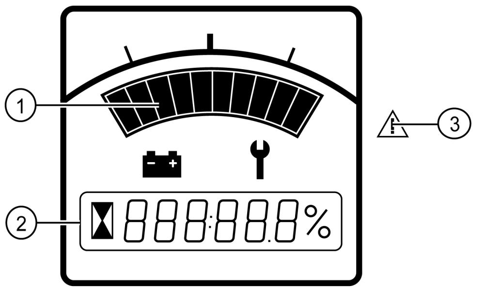
Figure 8. Multi-function display
1. Level of battery charge 2. Indication of operational hours, system messages and fault codes 3. LED indicator
Copyright© 2013 by MCFE. All rights reserved. Revision: B Document ID: 616843 26 (338)
The multi-function display shows the following information:
• Level of battery charge • Indication of operational hours • System messages: ECO = Economy mode selected Lo SPd = Low speed mode selected • Fault codes:
Numeric code = warning or alarm. For information about warnings and alarms, see chapter 13. • LED indicator:
Flashing red = alarm
4.3.4 Driving position
A pallet truck equipped with a foldable operator’s platform can be driven either walking behind the truck (the pedestrian mode) or standing on the platform (the riding mode).
4.3.4.1 Pedestrian mode
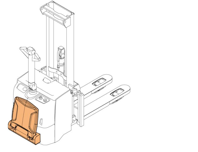
Figure 9. Pedestrian mode
To drive the truck in the pedestrian mode, lift the operator’s platform up by lifting it slightly and allowing the gas spring to lift it up completely.
To drive the truck in the direction of the forks, walk behind the truck and keep both hands on the tiller arm. To drive in the opposite direction, walk beside the truck and keep one hand on the tiller arm.
Copyright© 2013 by MCFE. All rights reserved. Revision: B Document ID: 616843 27 (338)
NOTE: The maximum driving speed in pedestrian mode is 6 km/h.
4.3.4.2 Riding mode
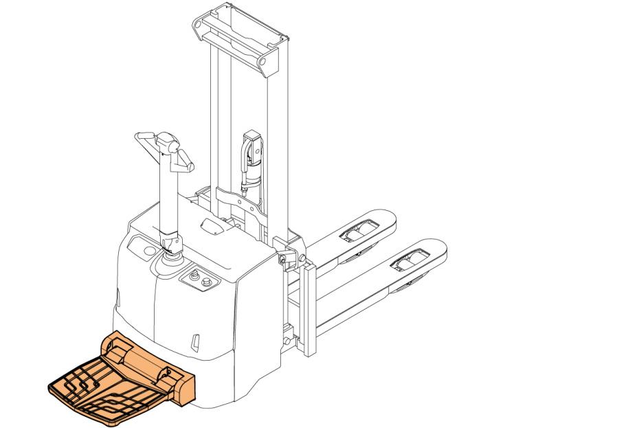
Figure 10. Riding mode
To drive the truck in the riding mode, lower the operator’s platform to the horizontal position, step on the platform and keep both hands on the tiller arm. When you step off the platform, it stays in the horizontal position automatically.
NOTE: The maximum driving speed in the riding mode is 6 km/h.
Copyright© 2013 by MCFE. All rights reserved. Revision: B Document ID: 616843 28 (338)
4.3.5 Driving direction
In the riding mode, the driving direction is as follows:
• To go forward, drive the truck in the direction of the forks. • To go backward, drive the truck in the opposite direction.
In the pedestrian mode, the forward driving direction is reversed.
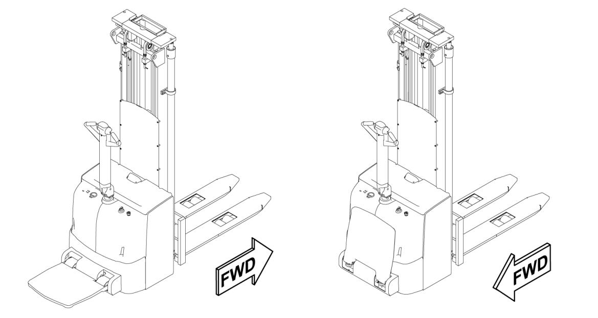
Figure 11. Driving direction
NOTE: The forward-driving direction is determined in EN ISO 3691-1:2012 Annex A.
Copyright© 2013 by MCFE. All rights reserved. Revision: B Document ID: 616843 29 (338)
4.3.6 Motor and electrical system
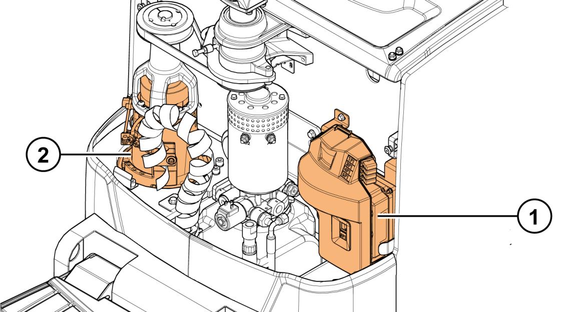
Figure 12. Overview of the motor and electrical system
1. Electric panel (covered with a plastic controller cover) 2. Drive unit
Copyright© 2013 by MCFE. All rights reserved. Revision: B Document ID: 616843 30 (338)
4.3.6.1 Electric panel
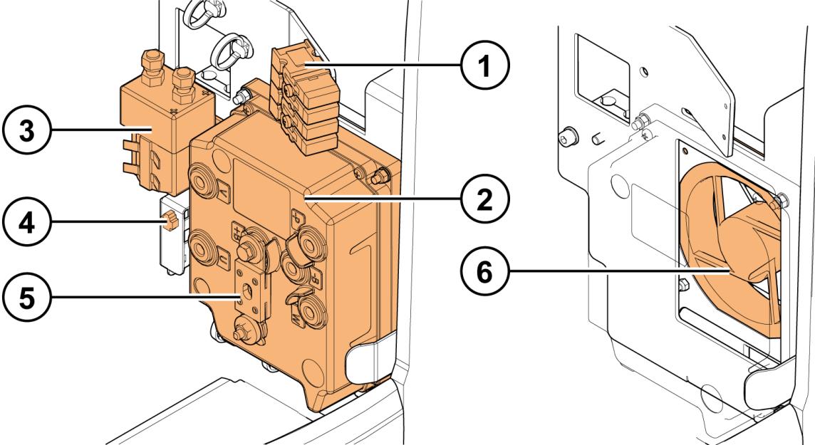
Figure 13. Electric panel overview
1. Fuse box 2. Traction and pump controller with the drive/pump motor fuse 3. Main contactor K1 4. Diagnostic connector X10 5. Main fuse 6. Controller fan (behind the electric panel)
Copyright© 2013 by MCFE. All rights reserved. Revision: B Document ID: 616843 31 (338)
4.3.6.2 Motor compartment
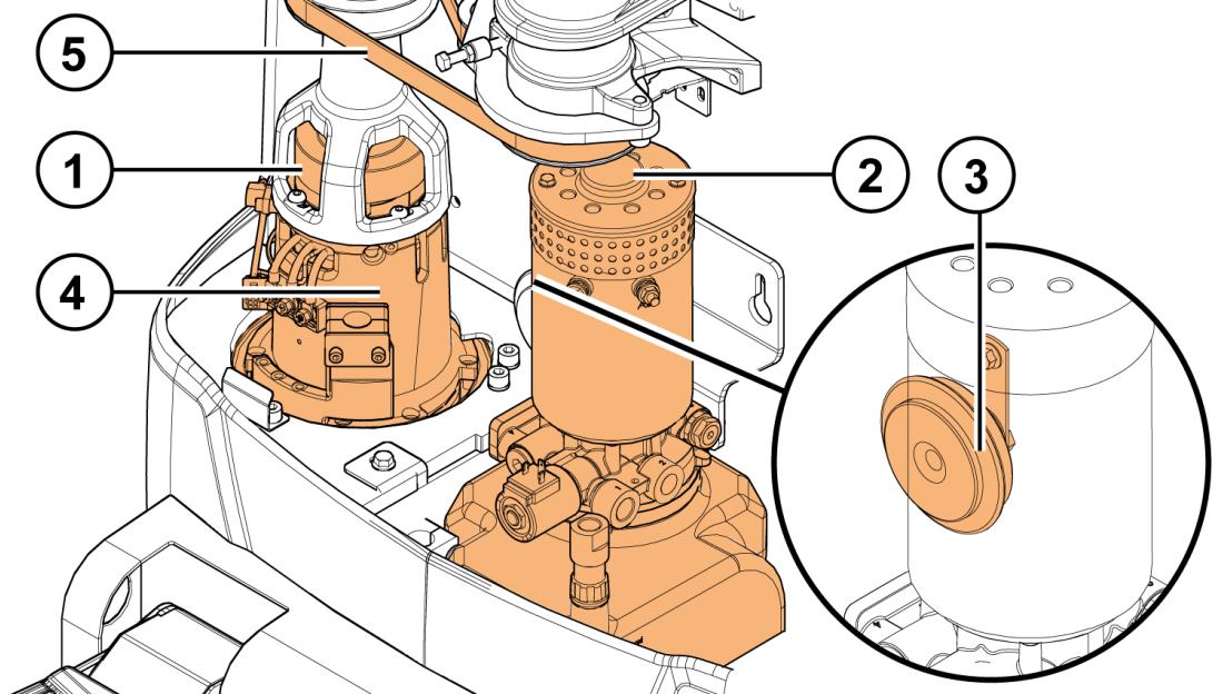
Figure 14. Motor compartment overview
1. Magnetic brake 2. Hydraulic aggregate 3. Horn 4. Traction motor 5. Motor belt
Copyright© 2013 by MCFE. All rights reserved. Revision: B Document ID: 616843 32 (338)
4.3.6.3 Traction motor
Type 3-phase AC
Voltage 16 V
Output power 2.3 kW
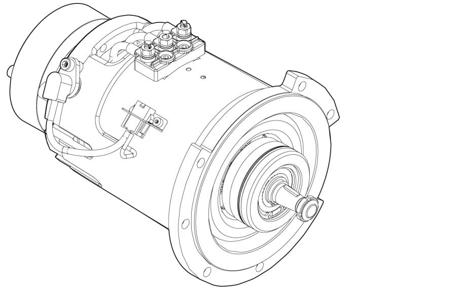
Figure 15. Traction motor
The correct tightening torque for the traction motor power terminals is 6 Nm.
Copyright© 2013 by MCFE. All rights reserved. Revision: B Document ID: 616843 33 (338)
4.3.7 Sensors
An inductive sensor is an electronic proximity sensor, which detects metallic objects without touching them.
The sensor consists of an induction loop. Electric current generates a magnetic field that collapses, thus generating a current that falls asymptotically toward zero from its initial level, when the electricity input ceases. The inductance of the loop changes according to the material inside it and, since metals are much more effective inductors than other materials, the presence of metal increases the current flowing through the loop. This change can be detected by sensing circuitry, which can signal to some other device whenever metal is detected.
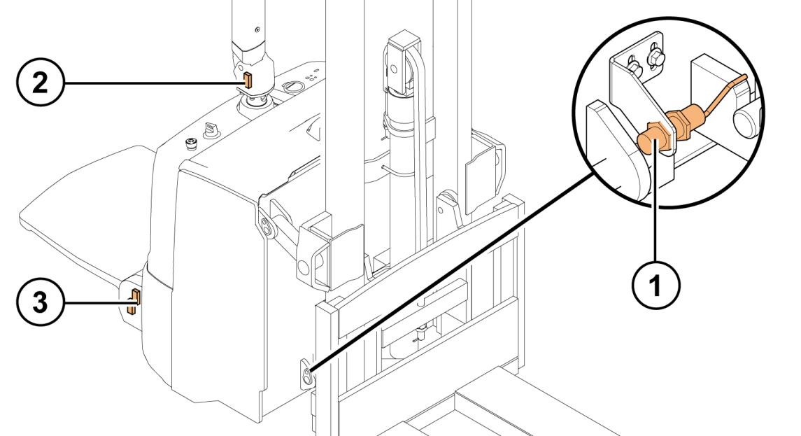
Figure 16. Sensor locations
1. Tiller sensor 2. Initial lift upper limit sensor (only with initial lift masts) 3. Operator’s platform sensor
The truck uses the following sensors:
• Tiller sensor
• Initial lift upper limit sensor (only with initial lift masts) • Operator’s platform sensors, two on the right-hand side.
Copyright© 2013 by MCFE. All rights reserved. Revision: B Document ID: 616843 34 (338)
4.3.8 Mast unit
The truck can be equipped with a simplex, duplex or triplex mast unit, depending on the functional needs for the truck. The mast units can also be equipped with straddle forks, which enable closed pallet handling, or with initial lift, which makes pallet handling more versatile, enables double-pallet handling and increases the truck’s ground clearance in ramp operations.
4.3.8.1 Simplex mast units
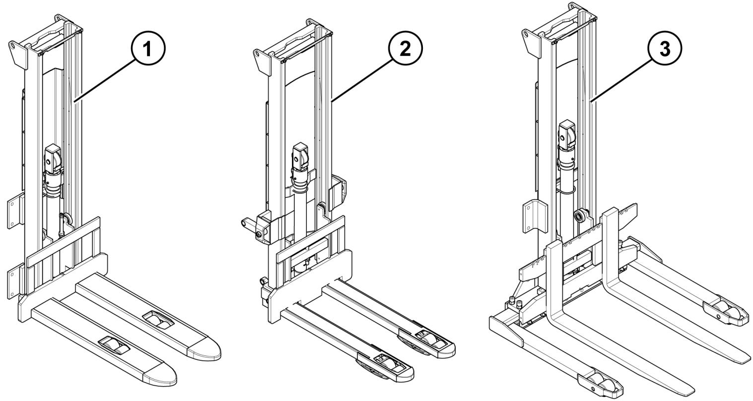
Figure 17. Simplex mast units overview
1. Simplex mast 2. Simplex mast with initial lift 3. Simplex mast with straddle fork
Copyright© 2013 by MCFE. All rights reserved. Revision: B Document ID: 616843 35 (338)
4.3.8.2 Duplex mast units
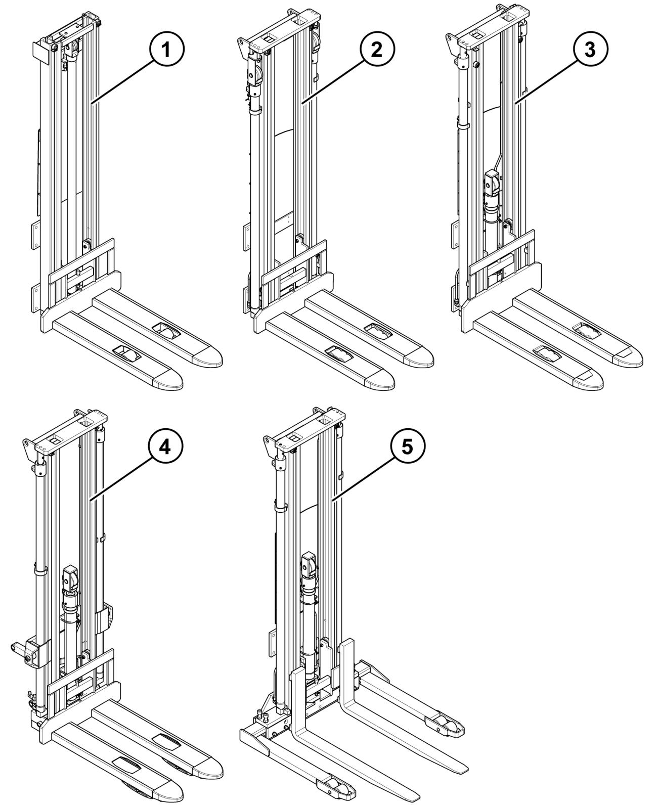
Figure 18. Duplex mast units overview
1. Duplex mast with one lift cylinder 2. Duplex mast with two side cylinders 3. Duplex mast with free lift 4. Duplex mast with free lift and initial lift 5. Duplex mast with straddle fork
Copyright© 2013 by MCFE. All rights reserved. Revision: B Document ID: 616843 36 (338)
4.3.8.3 Triplex mast units
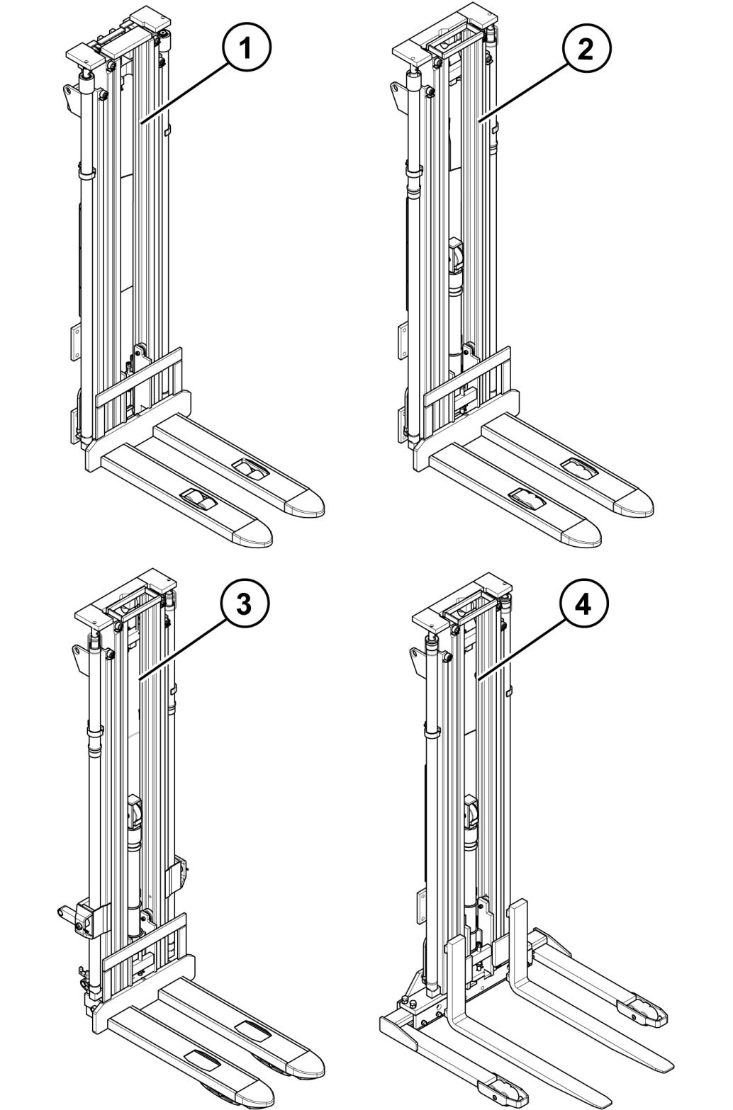
Figure 19. Triplex mast units overview
1. Triplex mast with two side cylinders 2. Triplex mast with free lift 3. Triplex mast with free lift and initial lift 4. Triplex mast with free lift and straddle fork
Copyright© 2013 by MCFE. All rights reserved. Revision: B Document ID: 616843 37 (338)