59 minute read
connector X6
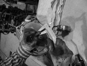
Figure 3.19. Checking the brake pad thickness
4. After checking/replacing the brake pad, clean the brake unit from any accumulated dust with pressurised air. Follow work safety procedures when using pressurised air and use a low pressure.
5. After the above procedures, reattach the brake unit to the drive unit.
3.7.5.2. 1,600 kg capacity trucks
Check the wear of the brake pad by measuring the air gap. If the air gap is within acceptable limits, only cleaning the brake with pressurised air is necessary.
To service the brake:
1. Remove the rubber gasket over the brake air gap.
51
52 Figure 3.20. Removing the rubber gasket
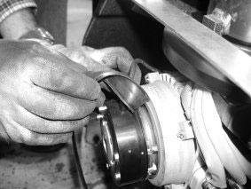
2. Use a feeler gauge to measure the air gap of the brake.
Measure the air gap at three points near each fixing screw.
The air gap should be between 0.2 and 0.55 mm and equal at each point.The air gap increases as the brake pad wears.
If the air gap is within limits and equal at each point, continue directly to Step 5. Otherwise, continue to Step 3.
3. To adjust the air gap, loosen the three fixing screws with a 7 mm wrench and adjust the gap with the adjustment nuts in the brake. Retighten the fixing screws and measure that the air gap is within limits and equal at each point. Repeat this procedure if necessary to set the air gap as near 0.2 mm as possible to allow for wear. If the adjustment is successful, continue directly to Step 5, otherwise continue to Step 4.
4. If the brake pad has worn so much that the air gap can no longer be adjusted, the pad should be replaced. If the pad must be replaced, open the brake completely, remove the old brake pad and replace it with a new brake pad.The thickness of a new brake pad should be 8.5 mm.
Reassemble the brake after replacing the brake pad and return to Step 3.
5. After the brake has been checked and possibly serviced, it must be cleaned. Use pressurised air to remove any
accumulated dust from the brake. Follow work safety procedures when using pressurised air and always use a low pressure.
6. After the above steps, reattach the rubber gasket. Carefully position the gasket so that its skirt falls into the grooves on both sides to seal the enclosure.
3.7.6. Checking the fastening of the transmission and the drive unit
Check that the drive unit fixing bolts and the main transmission bolts are securely fastened.
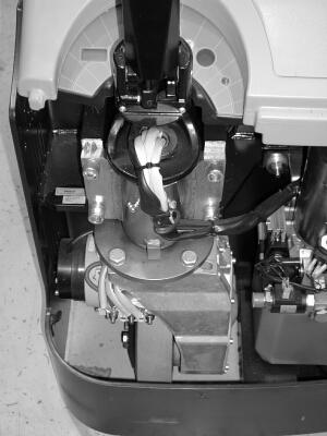
Figure 3.21. Drive unit and main transmission fixing bolts
For this check, access the checking hole on the side of the transmission unit. If you need to lift the truck to perform the check, make sure that it remains level while performing this check. Remember cleanliness and follow fluid safety procedures.
To check the fluid level, open the cap of the checking hole with a 5 mm Allen key. If the fluid level is clearly lower than the edge of the checking hole, you must add transmission fluid. For more
53
information on adding transmission fluid, refer to Section 3.8.2 Changing the transmission fluid (1,600 kg capacity trucks only). Refer to Section 3.9 Lubricant and fluid recommendations for fluid recommendations.
3.8. Annual maintenance (after 1,200 hours of operation)
Annual maintenance should be carried out either after a year or after 1,200 hours of use, whichever is sooner. If the truck is equipped with an operating time meter, annual maintenance is easy to schedule. If not, the operating time can be read using the console. Refer to Chapter 4 Electrical operation and maintenance for more information on using the console.The annual maintenance procedures should be carried out only by a trained professional.
3.8.1. Changing the hydraulic fluid
The hydraulic fluid must be changed once a year on all truck models. Note that the filling cap functions as a breather for the tank, so do not overtighten it or overfill the tank to avoid leakage. Refer to Section 3.9 Lubricant and fluid recommendations for fluid recommendations. Remember cleanliness and follow the precautions for handling harmful fluids.
To change the hydraulic fluid, begin by removing the truck's main cover.The hydraulic pump and tank assembly is located in the middle of the main chassis with the tank at the bottom and the pump and motor above it. Open the filling cap. Use a draining apparatus to drain the used fluid from the tank. Ensure that all the tools and tubing you use are clean.
54
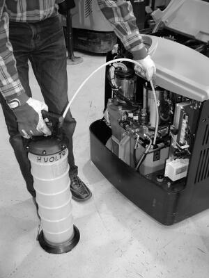
Figure 3.22. Draining the hydraulic tank
After the tank has been drained, fill it with new hydraulic fluid to three-quarters (¾) of its capacity. Do not overfill. Be careful to avoid splashing the hydraulic fluid onto truck components. Immediately wipe away any splashes. Close the cap, but be careful not to overtighten it.
Change the transmission fluid once a year on 1,600 kg capacity trucks.The transmission has three orifices: the filling hole (1) at the top, the checking hole (2) on the side, and the draining hole (3) on the underside.
55
NOTE
Figure 3.23. Location of filling (1), checking (2) and draining (3) orifices
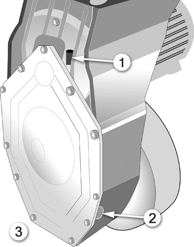
The filling cap is opened with a 12 mm wrench, while the checking and draining hole caps require a 5 mm Allen key.Take precautions for handling transmission fluid and keep the servicing area clean.
To change the transmission fluid:
1. Lift the truck with a suitable jack or other safe method and secure it to a level position. Always secure the truck so that it is safe to work under. Never work under a truck that is supported only by jacks.
2. After the truck has been lifted and levelled, place a suitable container under the transmission draining hole.There is approximately 0.6 litres of fluid in the transmission.
3. Open the draining hole cap using a 5 mm Allen key.
56
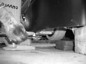
Figure 3.24. Opening the draining cap
4. Open the filling hole cap using a 12 mm wrench and let the transmission fluid drain completely.
5. Close the draining hole cap.
6. Open the checking hole cap using a 5 mm Allen key.
7. Using a funnel, pour new transmission fluid carefully into the filling hole until it reaches the level of the checking hole.
Refer to Section 3.9 Lubricant and fluid recommendations for fluid recommendations.
8. Close the checking and filling hole caps.
3.9. Lubricant and fluid recommendations
Take the appropriate precautions when handling lubricants and fluids during maintenance. Many of the used fluids are harmful or even toxic, and some solutions are corrosive. Always use protective clothing, eyewear and gloves when handling harmful fluids. Refer and conform to all local safety guidelines governing these fluids and lubricants. Before use, always familiarise yourself with a substance by reading the instructions and precautions for use from the container or associated documentation. Never handle an open flame or smoke a cigarette in or near the area where these substances are handled.
57
3.9.1. General lubricant
Use grease that conforms to NLGI grade No. 2 requirements as the general lubricant for moving parts in trucks. If the truck is used in cold environments, such as cold store applications, use NLGI No. 1 or No. 0.
3.9.2. Battery fluid
Use fluid intended for lead-acid batteries as the battery fluid for trucks with serviceable batteries. Never use any other fluid to fill the battery cells.
3.9.3. Hydraulic fluid
Normally use fluid of the ISO VG 32 viscosity class as the hydraulic fluid. Use fluid of the ISO VG 15 viscosity class in cold environments.
3.9.4.Transmission fluid
The transmissions of 1,000 and 1,200 kg capacity trucks are grease filled at the factory and do not require service. Use transmission fluid of grade EP 80 or 90 as the transmission fluid for 1,600 kg capacity trucks.
58
4. Electrical operation and maintenance
This chapter examines the electrical aspects of the truck.The chapter begins with a description of the truck's electrical operation. It continues by introducing the console and presents its use in reading and modifying controller parameters.The chapter concludes with electrical maintenance and repair instructions not covered in Chapter 3 Regular maintenance.
Refer to Section 3.1 Safety guidelines and preparation and Section 3.2 Maintenance guidelines for information on safety and preparation for maintenance tasks. Refer to Chapter 2 Operating the truck for operating instructions.
4.1. Electrical operation
This section presents the truck's primary electrical functions. Ensure that you have the correct version of the electrical schematics for the truck model under maintenance. Contact your supplier or technical support for information on obtaining up-to-date documentation for your truck.
The section assumes that you are using the standard model of the truck.This chapter only addresses the primary electrical functions.To troubleshoot a particular component, you need to locate it on the electrical schematic diagram to understand how it is connected to the entire system. Keep a copy of the electrical schematic diagram at hand while reading this chapter.
4.1.1. Using the schematic diagram
NOTE
Always acquire the correct version of the electrical schematics before proceeding with electrical maintenance.
The electrical schematic diagram is divided into zones, which are presented along the top edge of each page. Use these zones as a navigating aid to locate components. For example, the text may refer to a component in a certain zone of a certain page of the schematics.
4.1.2. Power source
The truck is powered by a wet lead-acid battery, which consists of 12 cells and supplies a nominal voltage of 24 V. Depending on the truck model, the battery has a capacity between 160 and
59
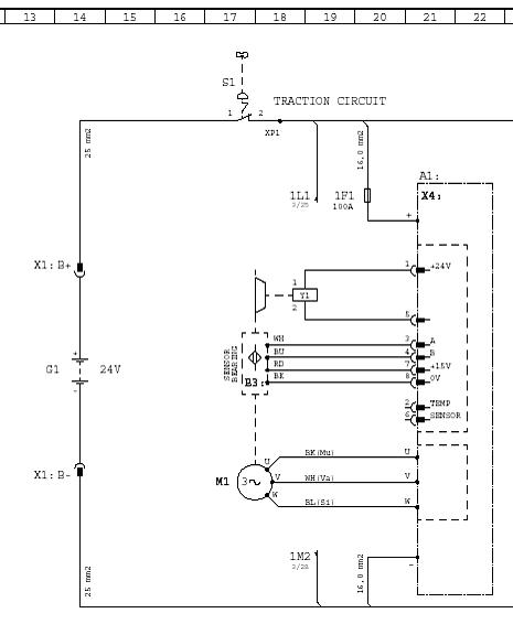
345 Ah.The batteries reside in a separate compartment and are connected to the system via the X1 battery connector.The battery is presented as G1 in zone 14 on page 1 of the electrical schematic diagram.
4.1.3. Key switch
The main key switch S1 controls the electrical power supply to the entire system. It also functions as the emergency stop button. The main key switch is activated by pulling it up, which closes the switch. If the system needs to be powered down at any time, the key switch can be pressed.This opens the S1 switch connection.The switch is located in zone 17 or 18 on page 1 of the electrical schematic diagram.
When the main key switch closes the contact, electrical power is supplied to the system. Power is routed directly to the optional PIN code lock and possible hydraulic control unit (HCU), and through the main fuses 1F1 and 2F1. Fuse 1F1 supplies the battery positive voltage B+ to the traction controller and is rated
60
at 100 A on all truck models. Fuse 2F1 supplies B+ to the K1 pump motor contactor and is rated at 150 A on all truck models. Refer to the electrical schematic diagram for the location of the main fuses in zones 20 and 24 on page 1.
After the main fuse 1F1, the B+ supply is fed to the main positive input terminal of the traction controller.The positive power feed is internally connected to the auxiliary fuse A1F1 in the traction controller. Fuse A1F1 is rated at 5 A. Refer to zone 21 on page 1 of the electrical schematic diagram.The battery negative pole B- is connected directly to the negative input terminal of the traction controller.
Control of the K1 pump motor contactor depends on the truck model.The contacts of the contactor are presented in zone 24 on page 1 of the electrical schematic diagram.The contacts of the contactor are controlled either by the traction controller or by the hydraulic control unit (HCU).When controlled by the traction controller, the coil controlling the contacts is presented in zone 18 on page 2 of the electrical schematic diagram.When a hydraulic control unit (HCU) is installed, K1 is controlled by the coil presented in zone 21 on page 3 of the electrical schematic diagram.The contactor coil is powered as long as the truck’s battery power is high enough. Lifting is disabled when the battery
61
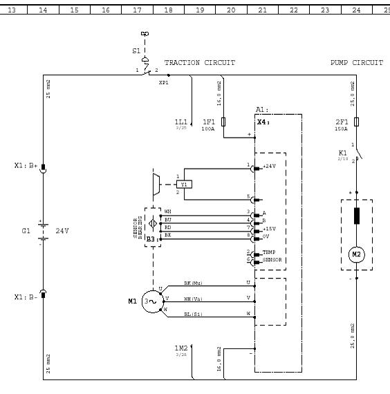
voltage drops under the level set with the Level low batt. parameter of the traction controller. Refer to Section 4.2 Console for information on reading and modifying the parameters of the traction controller.
4.1.4.Traction
The movement of the truck is controlled by the traction controller. Before the truck can be driven, the battery must be connected, the main key switch must be closed (in the up position) and the system must have passed the self-test procedure.
When the truck is powered on and in standby mode, it can be driven by moving the accelerator at the end of the tiller arm towards the forward or backward direction.The accelerator is presented in zones 18 to 21 on page 2 of the electrical schematic diagram. Refer to Chapter 2 Operating the truck for more information on driving the truck.
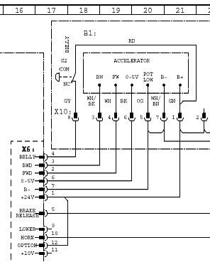
The accelerator unit receives its 24-volt electrical supply from pin 1 of connector X6.The negative connection is supplied through pin 7 of connector X6. As the accelerator is moved in either direction, it indicates the direction to the traction controller via pins 2 and 3 of connector X6. It also provides a varying voltage to pin 6 of connector X6.The voltage varies between approximately 0.3 and 5 V, and depends on the position of the
62
NOTE
accelerator control.The voltage increases as the accelerator is moved to either extreme. If the accelerator needs to be replaced for any reason, the sensor values should be reread using the console. Refer to Section 4.3.2.38 Parameter 251: Program throttle for information on the Program throttle parameter.
When the voltage at pin 6 of connector X6 of the traction controller rises above 0.3 V, the controller first checks the directional inputs (pins 2 and 3 of connector X6) for a direction indication.The controller also checks for any internal errors. Before the controller engages the traction motor, it releases the 1Y1 electrical parking brake.
The brake is controlled through pins 1 and 5 of connector X4. The parking brake is active when it receives no power, that is, also when the truck is powered down.To release the brake, the traction controller applies 24 V to pin 1 of connector X4 for one second and then reduces the voltage to 60% to hold the brake open. Refer to zone 18 on page 1 of the electrical schematic diagram.
63
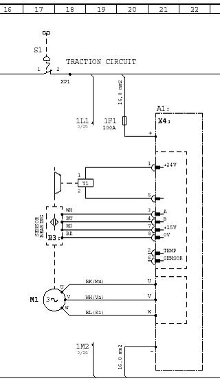
64 After the parking brake is released, the traction controller begins to feed the three-phase alternating current to drive the M1 traction motor.The AC traction motor is connected to the U, V and W outputs of the traction controller. Refer to zones 17 to 21 on page 1 of the electrical schematic diagram.
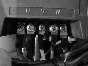
Figure 4.1.Traction motor connections
The truck is powered by a DC battery.The direct current is converted in the traction controller to three-phase alternating current to drive the AC traction motor.This process is known as inverting.The three motor inputs are driven out of phase to create a voltage drop between the phases.The order of the phases, that is, which phase is leading and which phases follow, determines the rotating direction of the motor.
The rotating speed of the motor is relational to the width and frequency of the pulse.The greater the pulse width, the longer current flows through the motor.The actual current passing through the motor is more sinusoidal than pulsed due to the characteristics of an inductor.The pulse width varies depending on feedback from the traction speed encoder bearing B3. If the motor revolves faster than the speed reference, the pulse width is decreased and vice versa.
Motor speed feedback allows the control system to maintain an exact speed, regardless of the load on the truck.The feedback process continues until the request to move ends. In other words, until you release the accelerator or an alarm occurs, which forces
NOTE
the traction controller to cease operation and to engage the brake. If there are no alarms when the accelerator is released, the traction controller reverses the motor phasing to slow it down (by attempting to reverse its rotating direction).The parking brake is engaged once the motor has stopped revolving, which the traction controller senses via the traction speed encoder. The maximum forward and backward travel speeds of the truck can be modified with the console.The maximum permitted speed of a pedestrian truck is 6 km/h. Refer to Section 4.2 Console for more information on using the console to adjust parameters.
The traction speed encoder is connected to the traction controller at pins 3, 4, 7 and 8 of connector X4. Pin 7 supplies the encoder with 15 volts while pin 8 supplies the negative connection. Pin 3 is encoder channel A and pin 4 is encoder channel B.
The traction controller determines the rotating speed of the motor by counting the pulses produced by the encoder over a certain period.The faster the motor turns, the more pulses are generated during the monitoring period.The rotating direction of the traction motor is determined by comparing the signals of the two channels.The motor’s turning direction causes the signal of one channel to lead while the other lags. The operation of the traction speed encoder can be tested using the console. Refer to Section 4.2 Console for more information on using the console.
NOTE
4.1.5. Braking
The truck is normally slowed down with the traction motor.When the truck is being driven in one direction, reducing the deflection of the accelerator control causes the system to reduce the speed reference to the traction motor, which actively reduces the speed. The operator can slow down the truck more rapidly by turning the accelerator in the opposite direction to the movement.This causes the traction controller to instruct the traction motor to reverse its movement and therefore to rapidly reduce its turning speed. If the accelerator is held in this position after the truck has stopped, it begins to move in the given direction at the requested speed.
In practice, when the accelerator is turned opposite to the direction of movement, the traction controller switches the order of the two of the three motor input phases (U, V and W).This action forces the traction motor to reverse its rotating direction.
65
NOTE
This will initially slow down the motor and then begin to turn it in the opposite direction. Braking characteristics can be adjusted with the Reverse braking parameter. Refer to Section 4.2 Console and Section 4.3.2 Parameters for more information on setting truck parameters with the console.
When the movement of the truck is slowed down with the motor, the motor acts as a generator and produces electrical power. This power is used to recharge the truck’s battery.This is known as regenerative or inverse braking. In this situation, the motor produces AC voltage from each of its phases.This AC voltage is rectified to a direct positive and negative voltage. As long as the resultant DC voltage is higher than the battery voltage, the battery is charged.
The truck is equipped with an electrical brake, but this is normally not used to control the truck’s speed.The Stop mode tiller parameter controls the function of the electrical brake. In the default mode, the electrical brake is engaged only after the truck's movement has stopped.This reduces the wear on the electrical brake.The electrical brake can be used to slow down the truck, but this is not recommended.
4.1.6. Safety button
The truck is by regulations obligated to have a safety button to protect the operator.The safety button is situated at the far end of the tiller arm. Its purpose is to stop and reverse the direction of the truck’s movement to minimise the risk of the operator being crushed between the truck and an obstacle.
The safety button works only when the truck is driven in the direction of the tiller arm.When the button is pressed, the truck automatically stops and reverses its movement for a short period. The sharpness of the response is controlled by parameter 142 and also by the original speed.The response is greater at faster driving speeds. Refer to Section 4.2 Console for more information on setting the truck’s parameters with the console.
The safety button S2 is located in zone 18 on page 2 of the electrical schematic diagram.When it is pressed, it opens the connection and removes the 24-volt electrical supply from pin 4 of connector X6.This causes the controller to connect the reverse direction.The reversing acceleration is set with parameter 142.
66
4.1.7. Lifting and lowering the forks
The forks are lifted hydraulically.The operator requests lifting or lowering by using the controls in the tiller arm head.The control layout varies by truck model and depends on the supported hydraulic functions.There are four possible configurations for the lifting hydraulics.These configurations are examined below. Refer to Chapter 2 Operating the truck for information on the truck's controls.
Lifting and lowering is controlled by microswitches in the tiller arm head. Lifting is requested with switch S4.The lowering function has two speeds, which are controlled by switches S5 and S7. Refer to zones 26-29 on page 2 of the electrical schematic diagram.
Lifting
When the operator requests lifting, switch S4 is closed, which sends the 24-volt signal via pin 6 of connector X18 to pin 8 of connector X6 of the traction controller.The traction controller reacts to the request only if the battery voltage is above the level defined by the Level low batt. parameter. If so, the traction controller energises the K1 contactor coil through pin 5 of connector X3. K1 closes and feeds the battery voltage to the pump motor, which begins to run.
Lowering
The lowering function has two speeds.The operator can request slow lowering by pressing the lowering control lightly and fast lowering by pressing the control firmly.When the operator requests slow lowering, switch S5 is closed, which sends the 24-volt signal via pin 12 of connector X18 to the 2Y1 magnetic lowering valve, which opens.When the operator requests fast lowering, switch S7 is also closed, which sends the 24-volt signal via pin 15 of connector X18 to the 2Y2 magnetic lowering valve. The lowering speed is increased, as both the 2Y1 and 2Y2 valves are open.
67
4.1.7.2.Trucks with initial lift (1,200 kg capacity model)
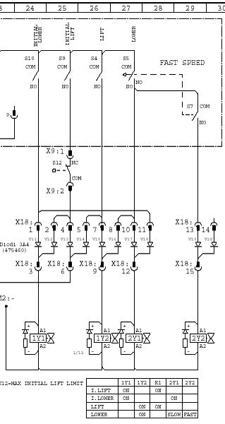
Lifting and lowering, as well as the initial lifting function, are controlled by microswitches in the tiller arm head. Lifting is requested with switch S4.The lowering function has two speeds, which are controlled by switches S5 and S7. Initial lifting is controlled by switch S9 and initial lowering by switch S10. Refer to zones 24-29 on page 2 of the electrical schematic diagram.
Lifting
When the operator requests lifting, switch S4 is closed, which sends the 24-volt signal via pin 6 of connector X18 to pin 8 of connector X6 of the traction controller.The 24-volt signal from switch S4 also opens the 1Y2 magnetic locking valve.The traction controller reacts to the request only if the battery voltage is above the level defined by the Level low batt. parameter. If so, the traction controller energises the K1 contactor coil through
68
pin 5 of connector X3. K1 closes and feeds the battery voltage to the pump motor, which begins to run. Hydraulic fluid is routed to the mast cylinder.
Lowering
The lowering function has two speeds.The operator can request slow lowering by pressing the lowering control lightly and fast lowering by pressing the control firmly.When the operator requests slow lowering, switch S5 is closed, which sends the 24-volt signal via pin 12 of connector X18 to the 2Y1 magnetic lowering valve, which opens.The 1Y2 magnetic locking valve is also opened.When the operator requests fast lowering, switch S7 is also closed, which sends the 24-volt signal via pin 15 of connector X18 to the 2Y2 magnetic lowering valve.The lowering speed is increased, as both the 2Y1 and 2Y2 valves are open.
Initial lifting and lowering
When the operator requests initial lifting, switch S9 is closed, which sends the 24-volt signal through the initial lifting limit switch S12 and pin 6 of connector X18 to pin 8 of connector X6 of the traction controller.The 24-volt signal from switch S9 also opens the 1Y1 magnetic locking valve.The traction controller reacts to the request only if the battery voltage is above the level defined by the Level low batt. parameter. If so, the traction controller energises the K1 contactor coil through pin 5 of connector X3. K1 closes and feeds the battery voltage to the pump motor, which begins to run. Hydraulic fluid is routed to the initial lifting cylinder. When the top position is reached, the initial lifting limit switch S12 opens and deactivates the pump motor and closes the 1Y1 magnetic locking valve.
When the operator requests initial lowering, switch S10 is closed, which sends the 24-volt signal via pin 3 of connector X18 to the 1Y1 magnetic locking valve and via pin 12 of connector X18 to the 2Y1 magnetic lowering valve. Both valves open and the hydraulic fluid from the initial lifting cylinder flows to the tank.
Lifting and lowering is controlled by a fingertip control lever in the tiller arm head.The control lever provides proportional control
69
of lifting and lowering. Refer to zone 27 on page 2 of the electrical schematic diagram.
Lifting
The operator requests lifting by moving the fingertip control in the lifting direction.The amount of deflection from the neutral position determines the lifting speed.When in the neutral position, the output of the fingertip control is 2.5 V at pin 12 of connector X3 of the hydraulic control unit (HCU).The 24-volt supply voltage of the fingertip control originates from pins 5 (positive) and 6 (negative) of connector X3 of the HCU.When the fingertip control output voltage increases above 2.5 V, the K1 pump contactor coil is energised via pins 1 (positive) and 7 (negative) of connector X2 of the HCU. K1 closes and feeds the battery voltage to the pump motor, which begins to run.
The HCU opens the M1 proportional valve fully by supplying it with the full control voltage at pins 4 (positive) and 5 (negative) of connector X1 of the HCU.The full control voltage is approximately 13 to 14 V depending on HCU parameter settings. This routes most of the hydraulic fluid back to the tank, which results in low pressure at the lifting cylinder. As the fingertip control is deflected further from the neutral position to request faster lifting, its output increases gradually to a maximum of 4.5 V.The control voltage of the M1 proportional valve correspondingly decreases gradually to 0 V.This reduces and eventually stops the flow of hydraulic fluid to the tank and increases the pressure at the lifting cylinder.
Lowering
When the operator requests lowering, the fingertip control output voltage decreases below 2.5 V.The M1 proportional valve is closed, as no control voltage is applied to it by the HCU. As the fingertip control is deflected further from the neutral position to request faster lowering, its output decreases gradually to a minimum of 0.5 V.The control voltage of the M1 proportional valve correspondingly increases from 0 V gradually to the full control voltage of approximately 13 to 14 V.This opens the valve and gradually increases the flow of hydraulic fluid from the lifting cylinder to the tank.
70
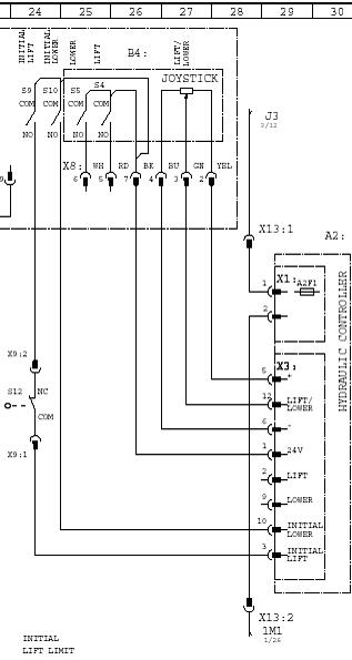
Lifting and lowering is controlled by a fingertip control lever in the tiller arm head.The control lever provides proportional control of lifting and lowering. Initial lifting is controlled by microswitch S9 and initial lowering by microswitch S10. Refer to zones 24-27 on page 2 of the electrical schematic diagram.
Lifting
The operator requests lifting by moving the fingertip control in the lifting direction.The amount of deflection from the neutral position determines the lifting speed.When in the neutral position, the output of the fingertip control is 2.5 V at pin 12 of connector X3 of the hydraulic control unit (HCU).The 24-volt supply voltage of the fingertip control originates from pins 5 (positive) and 6 (negative) of connector X3 of the HCU.When the fingertip control
71
72 output voltage increases above 2.5 V, the K1 pump contactor coil is energised via pins 1 (positive) and 7 (negative) of connector X2 of the HCU. K1 closes and feeds the battery voltage to the pump motor, which begins to run.
The HCU opens the M4 locking valve by supplying the control voltage through pins 3 (positive) and 9 (negative) of connector X2 of the HCU.The HCU opens the M1 proportional valve fully by supplying it with the full control voltage at pins 4 (positive) and 5 (negative) of connector X1 of the HCU.The full control voltage is approximately 13 to 14 V depending on HCU parameter settings.This routes most of the hydraulic fluid back to the tank, which results in low pressure at the lifting cylinder. As the fingertip control is deflected further from the neutral position to request faster lifting, its output increases gradually to a maximum of 4.5 V.The control voltage of the M1 proportional valve correspondingly decreases gradually to 0 V.This reduces and eventually stops the flow of hydraulic fluid to the tank and increases the pressure at the lifting cylinder.
Lowering
When the operator requests lowering, the fingertip control output voltage decreases below 2.5 V.The M1 proportional valve is closed, as no control voltage is applied to it by the HCU.The HCU opens the M2 magnetic valve to enable lowering by supplying the control voltage through pins 6 (positive) and 12 (negative). As the fingertip control is deflected further from the neutral position to request faster lowering, its output decreases gradually to a minimum of 0.5 V.The control voltage of the M1 proportional valve correspondingly increases from 0 V gradually to the full control voltage of approximately 13 to 14 V.This opens the valve and gradually increases the flow of hydraulic fluid from the lifting cylinder to the tank.
Initial lifting and lowering
When the operator requests initial lifting, switch S9 is closed, which sends the 24-volt signal through the initial lifting limit switch S12 to pin 3 of connector X3 of the HCU.The HCU opens the M3 locking valve by supplying the control voltage through pins 2 (positive) and 8 (negative).The K1 pump contactor coil is energised via pins 1 (positive) and 7 (negative) of connector X2 of the HCU. K1 closes and feeds the battery voltage to the pump motor, which begins to run.The HCU opens the M1 proportional
valve a predetermined amount by applying a voltage of approximately 5 to 6 V through pins 4 (positive) and 5 (negative) of connector X1 of the HCU.The control voltage depends on HCU parameter settings. Hydraulic fluid is routed at a constant pressure to the initial lifting cylinder.
When the operator requests initial lowering, switch S10 is closed, which sends the 24-volt signal to pin 10 of connector X3 of the HCU.The HCU opens the M3 locking valve by supplying the control voltage through pins 2 (positive) and 8 (negative).The HCU opens the M1 proportional valve a predetermined amount by applying a voltage of approximately 10 V through pins 4 (positive) and 5 (negative) of connector X1 of the HCU.The control voltage depends on HCU parameter settings.The hydraulic fluid from the initial lifting cylinder flows to the tank.
4.2. Console
The handheld console provides a user interface to the controllers used in trucks.The console can be used to verify the operation of the truck, read and modify controller parameter values, monitor the inputs and outputs of a controller, and display the error code when a fault has occurred.The console used in conjunction with these trucks is the BPK part number (RL)469054. Contact your supplier for information on obtaining a handheld console.
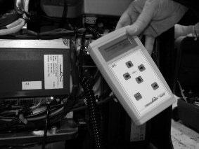
Figure 4.2. Handheld console, model BPK ((RL)469054)
73
4.2.1. Connecting the console
Before connecting the console, make sure that the truck’s main key switch is turned off.The console is connected to connector X7 of a controller.To access the connector, remove the main cover of the truck. Refer to Chapter 3 Regular maintenance for information on removing the truck’s covers.The connector may already be reserved by a peripheral device, such as a display unit. If so, simply disconnect the peripheral device to connect the console, and reconnect the peripheral device after disconnecting the console.
To connect the console:
1. Turn off the truck’s main key switch.
2. Open the main cover and locate the controller.
3. Disconnect a possible peripheral device (e.g. the display unit) from controller connector X7.
4. Connect the connection cable of the handheld console to connector X7 on the controller.
4.2.2. Navigating the parameter list
After the console is connected to the controller, the truck’s main key switch can be turned on. As the console goes through its start-up procedure, it first displays its own software version. After the start-up sequence, the console displays the serial number and software version of the controller to which it is connected.
The handheld console has six keys on its face: four arrow keys, an Esc key and an Enter key. Use the up and down arrows to scroll through the available parameters.
Press the down arrow from the first display to scroll to the first available parameter.The console displays “Searching next parameter” for a short period, then the name and number of the parameter, before displaying the name and value of the parameter.
Some controller parameters are diagnostic parameters and cannot be modified by the user.When you reach a modifiable parameter, press the left or right arrow key to enter editing mode. After the cursor has appeared, move it to the correct position
74
with the left and right arrow keys and modify the selected value with the up and down arrow keys.
When in editing mode, if a value is changed and no keys are pressed for one second, the new value is temporarily in use but has not been stored into the system.The Enter key must be pressed to store the value in the controller memory and to exit editing mode. If you wish to discard any changes and return to the previous stored value, press the Esc key to exit editing mode without storing the new value.
4.2.3. Accessing additional functions
The handheld console provides additional functions, which can be accessed by pressing the left and right arrow keys simultaneously.This opens a submenu with the following choices:
List of errors
This function displays a chronological list of the last eight controller faults that have occurred.The eight slots are reserved for different fault codes. If the same fault has occurred several times, it is displayed only once.
Write (BPK->dACi) and Read (dACi->BPK)
These commands are used to upload and download parameter sets to a controller.This can be useful, for example, when the controller must be replaced and settings must be moved to the new controller, or when several controllers are to be programmed with the same parameter set.
The Read (dACi->BPK) command is used to read and store the parameter values of a connected controller into the BPK handheld console.The handheld console has memory space to store up to eight parameter sets.When using this command, you are asked to select one of the available storage locations.
The Write (BPK->dACi) command is used to overwrite the parameter set of a connected controller. Once this function is selected, the console asks you to select one of the eight possible parameter sets to be downloaded to the controller. Be careful with this command, as it overwrites the entire parameter set of the connected controller.
Search device
75
When the connected controller is on a communication bus that contains other controllers, this function can be used to search for the device addresses of the controllers on the bus.
Select address
When the connected controller is on a communication bus that contains other controllers, this function can be used to connect the console to a different controller on the same bus.
Select language
Use this function to select one of the two available console user interface languages: English or German.
4.3.Traction controller
The traction controller is an important part of the truck’s electrical system. Depending on the truck model, it controls some or nearly all the electrical functions, such as driving, braking, lifting and lowering the forks, and the safety functions.The main task of the traction controller is to act as an inverter and convert the DC battery voltage to AC electrical power to drive the AC electrical motor.
4.3.1. Connections
As the electrical schematic diagram shows, the traction controller is connected to several electrical components of the truck.The traction controller A1 is presented on pages 1, 2 and 3 of the electrical schematic diagram.There are different models of the controller for different truck models.They, however, all function similarly. If the controller has to be replaced, contact your supplier or technical support for information on obtaining up-to-date documentation and parts for your truck.
76
NOTE
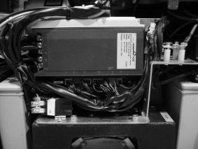
Figure 4.3.Traction controller
The traction controller has two main DC voltage inputs from the battery. It has three main AC voltage outputs to the three phases of the traction motor. In addition to these connections, the controller has several connectors for peripheral devices.The different connectors of the traction controller are listed below. Refer to the given sections of the electrical schematic diagram to locate the connectors.The actual physical location of the connectors on the traction controller varies by model, but is marked on its casing. The operation of the traction controller connections can be tested with the console. For more information, refer to Section 4.2 Console and Section 4.3.2 Parameters.
4.3.1.1. Connector X1 (zone 14, page 2)
X1, pin 1:The battery voltage is applied to this input in order to power on the controller.The input is protected by a 5 A fuse, which can be reached from outside the controller housing.This input provides the voltage supply for the other peripheral components.
Pins 2, 3 and 4 of connector X1 are not in use. Do not connect.
4.3.1.2. Connector X2
This connector is not used in this application. Do not connect.
77
4.3.1.3. Connector X3 (zone 17, page 2)
X3, pin 1:This pin supplies the 24-volt battery voltage to the safety socket switch S8 (zones 22-23, page 2). If the charging plug is removed from its socket, traction is disabled. Lifting is still permitted.
X3, pin 2: On non-HCU models, this 24-volt supply is connected directly to digital input pin 7. On HCU models, pin 2 is not connected.
X3, pin 3:The positive voltage supply for the H2 horn (zone 20, page 2).This output is controlled by input X6:10.
X3, pin 4: Not connected.
X3, pin 5: On non-HCU models, the positive voltage supply for the K1 pump motor contactor (zone 18, page 2).This output is controlled by input X6:8. On HCU models, pin 5 is not connected.
X3, pin 6:The digital input for the safety socket switch S8. See X3, pin 1.
X3, pin 7: On non-HCU models, connected directly to pin 2. On HCU models, pin 7 is not connected.
X3, pin 8:The negative connection for the horn H2.
X3, pin 9: Not connected.
X3, pin 10: On non-HCU models, the digital output for the K1 pump motor contactor. On HCU models, pin 10 is not connected.
4.3.1.4. Connector X4 (zone 21, page 1)
X4, pin 1:The positive 24-volt supply for the 1Y1 electrical brake (zone 19, page 1).
X4, pins 2 and 6: Connection for the motor temperature sensor. Not used in this application. Do not connect.
X4, pin 3: Channel A signal link from the B3 motor encoder (zones 17-18, page 1).
X4, pin 4: Channel B signal link from the B3 motor encoder.
X4, pin 5: Digital output for the 1Y1 electrical brake.
78
X4, pin 7:The 15-volt supply for the B3 motor encoder.
X4, pin 8:The 0-volt connection for the B3 motor encoder.
4.3.1.5. Connection X5 (zones 14-15, page 2)
X5, pin 1:The positive 24-volt supply for the H1 status LED (zone 11, page 2).
X5, pin 2:The positive 24-volt supply for the B2 tiller arm position switch (zones 12-13, page 2).
X5, pin 3: Input from the tiller arm position switch. Indicates that the tiller arm is in the driving position.
X5, pin 4: Digital output for the H1 status LED.
X5, pin 5:The 0-volt connection for the B2 tiller arm position switch.
X5, pin 6: Input from the tiller arm position switch. Indicates that the tiller arm is either in the upright or in the bottom position. In these positions, traction is disabled unless the S3 brake release switch is closed.
4.3.1.6. Connector X6 (zones 16-17, page 2)
X6, pin 1:The positive 24-volt supply for the B1 tiller arm head module (zones 17-30, page 2).
X6, pin 2: Digital input from the accelerator for the forward direction.
X6, pin 3: Digital input from the accelerator for the backward direction.
X6, pin 4: Digital input from the safety button (S2) (zone 18, page 2). Switch S2 is normally closed. If S2 is opened, the 24-volt supply is removed from this terminal and the traction controller acts accordingly.
X6, pin 5: Digital input from the brake release switch S3 (zone 22, page 2). By pressing this switch, the operator can drive the truck at reduced speed even when the tiller arm is in the upright or bottom position.
79
X6, pin 6:The speed reference input from the accelerator.
X6, pin 7:The battery negative connection for the B1 tiller arm head module.
X6, pin 8: On non-HCU models, the input for the lifting switch S4 (zone 26, page 2). Controls the X3:5 output. On HCU models, pin 8 is not connected.
X6, pin 9: Not connected.
X6, pin 10: Input for the horn switch S6 (zone 23, page 2). Controls the X3:3 output.
X6, pin 11: 10-volt output, 100 mA maximum current. Not connected.
X6, pin 12: Digital input for speed reduction. Not in use. Connected directly to pin 1.
4.3.1.7. Connector X7 (page 3)
This is the controller’s RS485 interface connector. If the truck is equipped with a display unit, it is connected to connector X7. The console connects to this connector. If a display unit is included, it must be disconnected before the console is connected. Refer to Section 4.2 Console for more information on using the console.
X7, pin 1: 15-volt supply.
X7, pin 2: 0-volt connection.
X7, pin 3: RS485, signal A.
X7, pin 4: RS485, signal B.
4.3.2. Parameters
There are two main parameter types in the controller: diagnostic and modifiable.The values of diagnostic parameters can be viewed but cannot be changed.The parameters available for the traction controller are presented below.Their order is determined by the parameter number, which controls the order in which they are listed on the handheld console.
80
NOTE
You may notice that not every parameter is available even for viewing.The console shows only those parameters that are meant to be user read or modified. Other parameters exist, but these are either not used in the current application or they have been preset by the manufacturer. Do not alter the value of a parameter unless you are completely certain of the necessity of the change and aware of how it affects the truck’s operation.
This parameter displays the version of the connected controller’s internal software.
This parameter displays the operating time of the connected controller.The time is displayed in hours and to an accuracy of three decimals.
4.3.2.3. Parameter 7: Serial number (diagnostic)
This parameter displays the serial number of the connected controller.
4.3.2.4. Parameter 10: Actual speed (diagnostic)
This parameter displays the actual current speed of the truck in km/h.
This parameter displays the speed reference value from the accelerator in km/h.
This parameter displays the temperature measured from the traction controller heat sink.The temperature is displayed in degrees Celsius (°C) and to an accuracy of one degree.
4.3.2.7. Parameter 18: Battery level (diagnostic)
This parameter displays the level of the battery charge.The level is displayed as a value between 1 and 10, with 1 indicating a level of 10% and 10 indicating 100%.
81
4.3.2.8. Parameter 30:Throttle value (diagnostic)
This parameter displays the speed reference value from the accelerator.The value is displayed as a voltage between 0 and 5 V, and to an accuracy of one decimal.When the accelerator is in the neutral position, the value should be close to 0 V.When the accelerator is moved to either extreme, the value should increase linearly close to 5 V.
This parameter displays the current measured battery voltage. The nominal voltage in this application is 24 V.The reading decreases while the truck is operated, as electrical power is drawn from the battery.
4.3.2.10. Parameter 46: Connector X1 (diagnostic)
This parameter displays the active pins of connector X1.
4.3.2.11. Parameter 47: Connector X2 (diagnostic)
This parameter displays the active pins of connector X2. Connector X2 is not used is this application.
4.3.2.12. Parameter 48: Connector X3 (diagnostic)
This parameter displays the active pins of connector X3.
Non-HCU models
In the standby state, the parameter displays pins 6, 7 and 10 (A=10). Pin 6 is the digital input of the safety socket. If the plug is removed from the safety socket, pin 6 should disappear from the display.When the safety socket is removed, the truck cannot be driven, but the forks can still be lifted. Pin 7 is directly connected to the 24-volt supply. Pin 10 is the digital output for the K1 pump motor contactor.
HCU models
In the standby state, the parameter displays pin 6, which is the digital input of the safety socket. If the plug is removed from the safety socket, pin 6 should disappear from the display.When the safety socket is removed, the truck cannot be driven, but the forks can still be lifted.
82
4.3.2.13. Parameter 49: Connector X4 (diagnostic)
This parameter displays the active pins of connector X4.The possible displayed pins are 3, 4 and 5. Pin 3 is the channel A input signal from the motor encoder bearing and pin 4 is the channel B signal. Pin 5 is active when the electrical brake is released.
You can test the encoder by driving the truck very slowly to observe the signals from the two encoder channels.When you start driving, pin 5 should appear to indicate that the electrical brake has been released. Pin 5 should not be displayed when the truck is stationary, as the electrical brake should be engaged. The sequence of pins 3 and 4 depends on the direction of travel. They could, for example, indicate the following sequence: first pin 3, then both pin 3 and pin 4, then only pin 4, then neither, then pin 3 again, and so forth.
4.3.2.14. Parameter 50: Connector X5 (diagnostic)
This parameter displays the active pins of connector X5.The possible displayed pins are 3, 4 and 6. Pin 3 indicates that the tiller arm is in the driving position. Pin 4 indicates that the status LED is illuminated. Pin 6 indicates that the tiller arm is either in the upright or in the bottom position.
When the truck is powered on and no faults have occurred, the status LED should be constantly illuminated, that is, pin 4 should be constantly displayed. If a fault has occurred, both the status LED and pin 4 flash in a pulse sequence that indicates the fault type. In other words, the error code can be counted from the sequence.
Move the tiller arm between the upright and bottom positions to check that the tiller switch works correctly.When the tiller arm is in the upright or bottom position, pin 6 should be displayed and the truck should not respond to driving commands, unless the brake release button is pressed.
4.3.2.15. Parameter 51: Connector X6 (diagnostic)
This parameter displays the active pins of connector X6.The possible displayed pins are 2, 3, 4, 5 and 12 (C=12). Pin 2 indicates that the digital input for the forward driving direction is active. Pin 3 indicates that the digital input for the backward
83
direction is active. Pin 4 indicates that the digital input of the safety switch is active. Pin 5 indicates that the digital input of the brake release button is active. Pin 12 indicates that the optional digital input is active.
When the truck is driven, pin 2 or 3 is displayed to indicate the driving direction. Pin 4 is normally displayed and disappears when the safety switch is pressed. Pin 5 appears when the brake release button is pressed to enable traction even when the tiller arm is in the upright or bottom position. Pin 12 (C) is displayed constantly, as it is an optional pin that has been hardwired to the 24-volt supply.
4.3.2.16. Parameter 60:Wheel diameter
This parameter is used to set the diameter of the drive wheel. The value is displayed in millimetres.The nominal wheel diameter is 230 mm.
4.3.2.17. Parameter 61: Gear ratio
This parameter is used to set the gear ratio of the truck’s transmission.The factor has been preset and should not be changed.The default value is 36.04 for 1,000 and 1,200 kg capacity trucks, and 30.1 for 1,600 kg capacity trucks.
4.3.2.18. Parameter 67: BDI curve
This parameter is used to select the algorithm used for battery discharge monitoring.The selection depends on the battery type. The default value is 3.
4.3.2.19. Parameter 68: BDI reset
This parameter sets the voltage value at which the system displays full battery charge.The default value is 25.08 V.
4.3.2.20. Parameter 69: BDI timer
This parameter determines a time period for battery discharge monitoring. Use the preset value. Do not change.The default value is 240.00 s.
84
4.3.2.21. Parameter 81: Lift cut-off
This parameter controls the lift cut-off function.When it is active, that is, set to 1, lifting is disabled when the low battery warning is triggered.The low battery warning level is set with parameter 175.
4.3.2.22. Parameter 98: Stop mode tiller
This parameter controls how the controller decelerates when the tiller arm is removed from the driving position.There are three choices, indicated by the number 1, 2 or 3.The default and recommended value is 2. Its advantage is that it reduces the wear of the electrical brake.The alternatives are:
1. The motor’s power feed is cut and the brake is applied at the same time.
2. The motor’s deceleration ramp is applied and the brake is engaged after the truck has come to a standstill.
3. The motor’s deceleration ramp is applied and the brake engaged at the same time.
4.3.2.23. Parameter 107:Warn. temp. contr.
This parameter sets the temperature level for the controller’s high temperature warning.The value is entered in degrees Celsius (°C) and can be between 50 and 79.The default value is 70, which should not be changed.
4.3.2.24. Parameter 133: Acceleration
This parameter controls the rate at which the truck accelerates when the accelerator is moved to request traction. Acceleration is given in km/h/s with an accuracy of two decimals and in the range from 0.50 to 6.00.The default value is 1.60.
4.3.2.25. Parameter 134: Deceleration
This parameter controls the rate at which the truck decelerates when the accelerator is released to request stopping. Deceleration is given in km/h/s with an accuracy of two decimals and in the range from 0.50 to 6.00.The default value is 2.50.
85
4.3.2.26. Parameter 137: Smoothing curve
This parameter affects the smoothing of the motor control curves. Its range is from 0 to 9, and the default setting is 5 for all truck models.This value should not be changed.
4.3.2.27. Parameter 138: Progress. curve
This parameter affects the progression of the motor control curves. Its range is from 0 to 100, and the default setting is 75 for all truck models.This value should not be changed.
4.3.2.28. Parameter 139: Reverse braking
This parameter controls the rate at which the truck decelerates when the accelerator is moved to the opposite direction of movement, that is, when performing reverse braking.The deceleration is given in km/h/s with an accuracy of two decimals and in the range from 0.50 to 6.00.The default value is 3.50 for all truck models.
4.3.2.29. Parameter 142: Dec. belly & tiller
This parameter controls the rate at which the truck decelerates when the truck is driven in the direction of the tiller arm and the safety button is pressed.The deceleration is given in km/h/s with an accuracy of two decimals and in the range from 0.50 to 9.00. The default value is 6.00 for 1,000 and 1,200 kg capacity trucks, and 5.00 for 1,600 kg capacity trucks.
4.3.2.30. Parameter 175: Level low batt.
This parameter sets the battery discharge level at which the low battery warning is triggered.The warning is triggered, if the battery level is below the set level for over three seconds.The parameter also sets the level at which the lift cut-off function activates (parameter 81 controls the lift cut-off function).The value range is from 1 to 5.The default value is 2 for 1,000 and 1,200 kg capacity trucks, and 1 for 1,600 kg capacity trucks.
4.3.2.31. Parameter 176: Low batt. speed
This parameter sets the speed reduction when the low battery warning is triggered. It sets the percentage of maximum speed (set by parameters 211 and 216) that is allowed when the low
86
battery warning is triggered.The value range is from 10% to 100%, and the default value is 33 for all truck models.
4.3.2.32. Parameter 211: Max. speed FWD
This parameter sets the maximum speed permitted in the forward direction.The value range is from 0.50 to 6.00 km/h.The default value is 5.60 km/h for 1,000 and 1,200 kg capacity trucks, and 6.00 km/h for 1,600 kg capacity trucks.
4.3.2.33. Parameter 216: Max. speed BWD
This parameter sets the maximum speed permitted in the backward direction.The value range is from 0.50 to 6.00 km/h. The default value is 5.60 km/h for 1,000 and 1,200 kg capacity trucks, and 6.00 km/h for 1,600 kg capacity trucks.
4.3.2.34. Parameter 221: Opt. speed limit 1
This parameter sets the optional speed reduction. It sets the percentage of the maximum speed permitted when using the option.The value range is from 10% to 100%, and the default value is 100%.The option is not used in this application.
4.3.2.35. Parameter 222: Brake rel. speed
This parameter sets the speed reduction when using the brake release function. It sets the percentage of maximum speed (set by parameters 211 and 216) that is allowed when the low battery warning is active.The value range is from 10% to 100%, and the default value is 33 for all models.
4.3.2.36. Parameter 223:Tiller type
This parameter sets the type of the installed tiller arm position switch. It has two values:“0” refers to an NO type switch and “1” refers to an NO/NC type switch.The default value is “1”. Do not change.
This parameter displays the current error code, if any. Refer to Section 4.3.3 Fault codes for an explanation of the possible error codes.
87
4.3.2.38. Parameter 251: Program throttle
This parameter is used to program the voltage range of the accelerator potentiometer into the controller.This procedure must be performed, if either the controller or the accelerator module in the tiller arm head is replaced. It can also be performed, if the truck does not seem to be responding correctly to the accelerator.
To program the voltage range:
1. Scroll to the Program throttle parameter.The console displays a value of “0”.
2. Press either the left or the right arrow key to activate the cursor.
3. Press the upward arrow key to change the value to “1”.
4. Press the Enter key to initiate the programming procedure.
5. During the 15-second programming period:
a. Move the accelerator smoothly to the maximum forward value.
b. Keep it held for one second.
c. Move it to the maximum backward value.
d. Keep it held for one second.
e. Return it to the neutral value.
6. If the procedure was successfully completed, the parameter value returns to “0” automatically.
The traction motor is disabled while the programming procedure is carried out.
NOTE
4.3.3. Fault codes
When a fault occurs while the truck is operated, truck functions are disabled and the status LED flashes to indicate a fault.The status LED flashes in a particular sequence, depending on the fault.The error code can be determined from the sequence. If the truck is equipped with a display unit, it displays the numerical
88
error code.The error code can also be read with the console by accessing the Error message parameter (249).This section presents the possible error codes with explanations.
4.3.3.1. Error:Watchdog
This fault does not have a numerical error code. It can be determined from the status LED.When the Watchdog error is triggered, the status LED flashes with the following sequence: pulse duty cycle 1:1 and frequency 1.25 Hz.
This error signifies an internal fault in the controller.When triggered, it disables the drive and digital outputs.The controller is faulty and must be replaced.
4.3.3.2. Error: RAM fault
This fault does not have a numerical error code. It can be determined from the status LED.When the RAM fault error is triggered, the status LED flashes with the following sequence: pulse duty cycle 1:3 and frequency 2.1 Hz.
This error signifies an internal fault in the controller.When triggered, it disables the drive and digital outputs.The controller is faulty and must be replaced.
4.3.3.3. Error: FLASH fault
This fault does not have a numerical error code. It can be determined from the status LED.When the FLASH fault error is triggered, the status LED flashes with the following sequence: pulse duty cycle 3:1 and frequency 2.1 Hz.
This error signifies an internal fault in the controller.When triggered, it disables the drive and digital outputs.The controller is faulty and must be replaced.
4.3.3.4. Error 2: New software version
This fault has error code number 2.The status LED indicates this fault by repeating the following sequence: two pulses and a pause.
This error appears only when a new software version is being loaded into the controller. It disables the drive and digital outputs. Reload the software as instructed.
89
4.3.3.5. Error 3: Overcurrent from power stage
This fault has error code number 3.The status LED indicates this fault by repeating the following sequence: three pulses and a pause.
When this error occurs, the drive is disabled.This error can occur if the controller was loaded for a long period at its current limit. The fault should not appear as long as motor speed monitoring functions correctly.The error can also appear, if a parameter that influences the controller current or the overcurrent shutdown level was modified.
Check the signals from the encoder bearing while the traction motor operates.The signals of channels A and B (pins 3 and 4 of controller connector X4) should appear in the correct sequence. If the sequence is incorrect, check the encoder cable and connections, and change the encoder if necessary.
If the problem is due to altered parameters, it may be resolved by returning to a previous parameter set.
4.3.3.6. Error 4: Low battery voltage
This fault has error code number 4.The status LED indicates this fault by repeating the following sequence: four pulses and a pause.
This error is triggered when the measured battery voltage drops below the level set with parameter 175 for more than three seconds. It causes the traction speed to be reduced to the level set with parameter 176. It also causes the lift cut-off function to activate, if it is enabled with parameter 81. If the battery voltage drops below the value set with parameter 173 (not accessible with the console) for more than three seconds, the controller is shut down.This fault can be reset only by switching the controller supply off and on.
This error can also be triggered, if there are too great voltage drops in the controller supply cables. Check the condition of the battery and the controller supply cabling.
90
4.3.3.7. Error 5: Battery overvoltage
This fault has error code number 5.The status LED indicates this fault by repeating the following sequence: five pulses and a pause.
This error is triggered when the measured battery voltage exceeds the value set with parameter 174 (not accessible with the console) for more than three seconds. It is also triggered if the battery voltage exceeds 150% of the nominal voltage.This fault should not occur, if the battery and the connections to the controller are intact (assuming that parameter 174 is correctly set).This error could also result from a damaged power stage in the controller.
Check that the connections between the battery and the controller are in good condition. Check the value of parameter 174, if possible. If the cause cannot be found, change the controller.
4.3.3.8. Error 6: Motor overtemperature
This fault has error code number 6.The status LED indicates this fault by repeating the following sequence: six pulses and a pause.
This error should not occur, as a motor temperature sensor is not used in this application.
4.3.3.9. Error 7: Controller overtemperature
This fault has error code number 7.The status LED indicates this fault by repeating the following sequence: seven pulses and a pause.
This error is triggered if the controller has overheated during operation.This may result from the controller being overloaded for a long period.This error can also result from a fault in the controller’s temperature measurement function.
Check that the controller is mounted according to the instructions so that it is able to dissipate heat efficiently. Check the controller’s output current. It should not exceed the unit’s nominal current. If the fault persists, the controller needs to be replaced.
91
4.3.3.10. Error 8: Drive signal monitoring
This fault has error code number 8.The status LED indicates this fault by repeating the following sequence: eight pulses and a pause.
This error indicates a fault with the accelerator.The error can be due to an incorrect operating sequence. After the controller is powered up, the following conditions must be true:
• Drive signals (X6:2 and X6:3) must not be present.
• Speed reduction must be active.
• The brake release switch (S3) must be open. ara>
• The tiller switch (B2) must not indicate driving position.
• The safety switch (S2) must be closed (i.e. not depressed).
• The safety socket (S8) must be closed.
• The speed reference signal (X6:6) must be near 0 V.
Check that the drive signals are working. Access parameter 51 with the console.Test that turning the accelerator in the forward direction provides the drive signal at pin 2 of connector X6 and that backward direction provides the drive signal at pin 3 of connector X6.
4.3.3.11. Error 9: Encoder bearing monitoring
This fault has error code number 9.The status LED indicates this fault by repeating the following sequence: nine pulses and a pause.
This error could indicate a fault in the encoder bearing or a broken connection between the encoder and the controller.
Check the encoder signals from channels A and B at pins 3 and 4 of connector X4. Refer to Section 4.3.2.13 Parameter 49: Connector X4 (diagnostic).
92
4.3.3.12. Error 10: Safety switch monitoring
This fault has error code number 10.The status LED indicates this fault by repeating the following sequence: ten pulses and a pause.
This error indicates a fault with the safety switch.The error can be due to an incorrect operating sequence. After the controller is powered up, the following conditions must be true:
• Drive signals (X6:2 and X6:3) must not be present.
• Speed reduction must be active.
• The brake release switch (S3) must be open.
• The tiller switch (B2) must not indicate driving position.
• The safety switch (S2) must be closed (i.e. not depressed).
• The safety socket (S8) must be closed.
• The speed reference signal (X6:6) must be near 0 V.
Use the console to check that there is a signal at pin 4 of connector X6. Refer to Section 4.3.2.15 Parameter 51: Connector X6 (diagnostic).
This fault has error code number 11.The status LED indicates this fault by repeating the following sequence: eleven pulses and a pause.
This error indicates a fault with the tiller switch.The error can be due to an incorrect operating sequence. After the controller is powered up, the following conditions must be true:
• Drive signals (X6:2 and X6:3) must not be present.
• Speed reduction must be active.
• The brake release switch (S3) must be open.
• The tiller switch (B2) must not indicate driving position.
• The safety switch (S2) must be closed (i.e. not depressed).
93
• The safety socket (S8) must be closed.
• The speed reference signal (X6:6) must be near 0 V.
Use the console to check that there is a signal at pin 6 of connector X5. Refer to Section 4.3.2.14 Parameter 50: Connector X5 (diagnostic).
4.3.3.14. Error 12: Accelerator monitoring
This fault has error code number 12.The status LED indicates this fault by repeating the following sequence: twelve pulses and a pause.
This error indicates a fault with the accelerator.The error can be due to an incorrect operating sequence. After the controller is powered up, the following conditions must be true:
• Drive signals (X6:2 and X6:3) must not be present.
• Speed reduction must be active.
• The brake release switch (S3) must be open.
• The tiller switch (B2) must not indicate driving position.
• The safety switch (S2) must be closed (i.e. not depressed).
• The safety socket (S8) must be closed.
• The speed reference signal (X6:6) must be near 0 V.
Use the console to check that the voltage value from the accelerator to pin 6 of connector X6 is close to 0 V when the accelerator is in the neutral position.The value can be checked with parameter 30 (refer to Section 4.3.2.8 Parameter 30:Throttle value (diagnostic)).
4.3.3.15. Error 14: EEPROM fault
This fault has error code number 14.The status LED indicates this fault by repeating the following sequence: fourteen pulses and a pause.
This error signifies an internal fault in the controller.The controller is faulty and must be replaced.
94
4.3.3.16. Error 15: Unrealistic U/f relationship
This fault has error code number 15.The status LED indicates this fault by repeating the following sequence: fifteen pulses and a pause.
This error indicates that there is a problem with the parameters that control the U/f relationship of the drive.
The error can be resolved by returning to a previous parameter set.
4.3.3.17. Error 16: Unrealistic speed input transfer function
This fault has error code number 16.The status LED indicates this fault by repeating the following sequence: sixteen pulses and a pause.
This error indicates that there is a problem with the parameters that control the speed input transfer function.
The error can be resolved by returning to a previous parameter set.
This fault has error code number 17.The status LED indicates this fault by repeating the following sequence: seventeen pulses and a pause.
This error indicates that the two tiller switch signals are not complementary.
Use the console to check the operation of the tiller switch (signals X5:3 and X5:6). Refer to Section 4.3.2.14 Parameter 50: Connector X5 (diagnostic).
4.3.3.19. Error 18: Speed reduction monitoring
This fault has error code number 18.The status LED indicates this fault by repeating the following sequence: eighteen pulses and a pause.
This error indicates a fault with the optional speed reduction function.The optional function is not used in this application.The
95
option connection on connector X6 is bridged to the 24-volt supply.
The error can be due to an incorrect operating sequence. After the controller is powered up, the following conditions must be true:
• Drive signals (X6:2 and X6:3) must not be present.
• Speed reduction must be active.
• The brake release switch (S3) must be open.
• The tiller switch (B2) must not indicate driving position.
• The safety switch (S2) must be closed (i.e. not depressed).
• The safety socket (S8) must be closed.
• The speed reference signal (X6:6) must be near 0 V.
Use the console to check that there is a signal at pin 12 (C) of connector X6. Refer to Section 4.3.2.15 Parameter 51: Connector X6 (diagnostic).
4.3.3.20. Error 19: Brake release monitoring
This fault has error code number 19.The status LED indicates this fault by repeating the following sequence: nineteen pulses and a pause.
This error indicates a fault with the brake release function.The error can be due to an incorrect operating sequence. After the controller is powered up, the following conditions must be true:
• Drive signals (X6:2 and X6:3) must not be present.
• Speed reduction must be active.
• The brake release switch (S3) must be open.
• The tiller switch (B2) must not indicate driving position.
• The safety switch (S2) must be closed (i.e. not depressed).
• The safety socket (S8) must be closed.
96
• The speed reference signal (X6:6) must be near 0 V.
Use the console to check that pressing the brake release button provides a signal at pin 5 of connector X6. Refer to Section 4.3.2.15 Parameter 51: Connector X6 (diagnostic).
4.3.3.21. Error 20: Safety socket monitoring
This fault has error code number 20.The status LED indicates this fault by repeating the following sequence: twenty pulses and a pause.
This error indicates a fault with the safety socket.The error can be due to an incorrect operating sequence. After the controller is powered up, the following conditions must be true:
• Drive signals (X6:2 and X6:3) must not be present.
• Speed reduction must be active.
• The brake release switch (S3) must be open.
• The tiller switch (B2) must not indicate driving position.
• The safety switch (S2) must be closed (i.e. not depressed).
• The safety socket (S8) must be closed.
• The speed reference signal (X6:6) must be near 0 V.
Use the console to check that there is a signal at pin 6 of connector X3 when the safety socket is in place. Refer to Section 4.3.2.12 Parameter 48: Connector X3 (diagnostic).
4.4. Hydraulic control unit (HCU)
Select models of the truck are equipped with a separate hydraulic control unit (HCU). On these models, the HCU handles the truck’s hydraulic functions instead of the traction controller.The HCU is present on models with proportional lifting of the forks.This can be determined from the presence of the fingertip lifting control lever on the side of the tiller arm head. If the controller has to be replaced, contact your supplier or technical support for information on obtaining up-to-date documentation and parts for your truck.
97


