14 minute read
battery voltage
If the truck is equipped with an hour meter, the meter shows the approximate level of battery charge when the truck’s main power is switched on. After charging, this indicator should read full battery charge.
If the battery does not seem to charge properly, does not hold a charge or presents other problems, refer to the battery maintenance section in Chapter 4 Electrical operation and maintenance for more information.
3.4.3. Checking the truck for external damage
Visually check the truck for any apparent problems or external damage. If damage is apparent, its extent should be checked and any necessary repairs made before continuing with regular maintenance. If the damage in any way affects the use or safety of the truck, the truck must be taken out of use until it is fully operational.
3.4.4. Checking the condition of the wheels
The truck has three wheel types: drive, load and castor.The drive wheel is located immediately under the tiller arm anchoring point and supports a considerable portion of the truck’s weight. It is attached to the drive motor via the transmission to propel the truck, and it is turned with the tiller arm to steer the truck.
33
34 Figure 3.4. Drive wheel
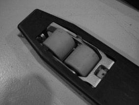
The load wheels are located near the ends of the forks.Their main purpose is to support the weight of the load. Depending on the truck model, there is either a single or a double load wheel in each fork.
Figure 3.5. Load wheels
The supporting castor wheel is located under the main chassis on the side opposite to the drive wheel.The purpose of the castor wheel is to balance the truck.The castor wheel turns automatically to follow the direction of travel.
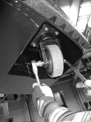
Figure 3.6. Castor wheel
Remove the main cover to gain better access to the wheels. Check all the wheels on a truck for damage and wear.The wheels should wear evenly, and there should be no flats or holes in the wear surface.The wheels should also turn smoothly on their axles and there should not be play in the bearings. Even wear can be tested by driving the truck on a smooth surface to test that all the wheels turn and the truck rides smoothly. If a wheel or a bearing has sustained damage that affects use or if its surface has worn completely, it should be replaced. Refer to Chapter 6 Mechanical maintenance for information on replacing and servicing wheels.
3.4.5. Checking that the batteries are securely fastened
The battery assembly sits on rollers in the battery compartment. The assembly is visible from both sides of the truck and can be removed from either side.The rollers under the assembly permit easy removal when necessary.The assembly is held in place with a fixing bracket, which can be opened and tightened by hand.
35
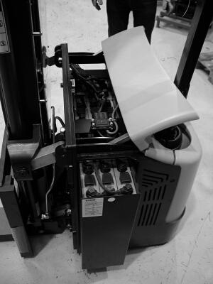
Figure 3.7. Battery assembly
Check that the assembly sits centrally in the battery compartment, so that it does not protrude from either side of the truck.Then open the battery compartment cover and check that the fixing bracket is correctly in place and tightened so that the battery assembly cannot move during use.
3.4.6. Checking the level of battery fluid in each cell
NOTE
Make sure that the battery is fully charged before checking the level of battery fluid.
Take appropriate precautions when handling batteries and battery fluid. Battery fluid is a corrosive acid solution and can cause burns if it comes into direct contact with bare skin. Use only approved fluid to fill the battery cells. Refer to Section 3.9 Lubricant and fluid recommendations for fluid recommendations.
Open the battery compartment cover to access the battery cells. Depending on the truck model and battery assembly type, it may be necessary to open the fixing bracket and slide out the battery assembly from the compartment to gain access to the battery cells.Follow the instructions issued by the battery or battery cell manufacturer for maintaining battery cells in good condition. Use care not to contaminate the solution with impurities. Do not overfill the cells and close the caps firmly to avoid leakage.
36
3.4.7. Checking the transmission for leaks
Visually check that there are no apparent fluid leaks in the transmission assembly. Open the main cover to perform this check.The transmission of 1,000 and 1,200 kg capacity trucks is service free and has been filled with grease to last its entire operating life.The transmission of 1,600 kg capacity trucks is fluid-filled and serviceable. It has a filling cap at the top, a checking cap on its side and a draining cap on the underside. Check that these caps are firmly fastened. Never use your hands to check for leaks.The amount of transmission fluid is checked during semi-annual maintenance (see Section 3.7.7 Checking the amount of transmission fluid (1,600 kg capacity trucks only)).
3.4.8. Checking the condition of hydraulic tubing and couplings
Visually check the condition of all accessible hydraulic lines and couplings. Open the main cover to perform this check.The location of hydraulic components differs between truck models, but you should check that all the accessible couplings and tubing in the hydraulic system are in good condition.There should be no evidence of leaks or damage. Follow the hydraulic system from the tank and pump assembly to all couplings.
The operation of the hydraulic system is tested during daily maintenance (see Section 3.4.13 Testing the lifting hydraulics and controls).The amount of hydraulic fluid in the system is checked during weekly maintenance (see Section 3.5.3 Checking the amount of hydraulic fluid).The hydraulic fluid in the system is changed annually (see Section 3.8.1 Changing the hydraulic fluid). If you find any problems or damage in the hydraulic system, the truck must be taken out of use until it is fully operational. Refer to Chapter 5 Hydraulic operation and maintenance for information on hydraulic maintenance.
3.4.9.Testing the operation and condition of the tiller arm
When the truck is not being used, the tiller arm must rest in the upright position. Check that the arm moves smoothly between the top and bottom positions. Check that the gas spring in the tiller arm returns the arm from any position to the upright position. Check that the tiller arm is securely fastened at its base. Check for any unwanted play in the moving parts. Note that the position of the tiller arm affects driving (see Section 3.4.11 Testing the
37
speed control unit, steering and the horn). If the tiller arm does not function properly or if it has sustained damage, the truck must be taken out of use until it is fully operational. Refer to Chapter 6 Mechanical maintenance for information on mechanical maintenance.
3.4.10.Testing the safety button
WARNING!
Never use a truck with a faulty safety button!
Check the operation of the safety button immediately after the main power switch is turned on.Test the operation of the safety button before continuing with the other operational tests.
Close all the covers before you switch on the main power. For the remaining daily maintenance tests, you have to switch on the truck’s main power. Refer to Chapter 2 Operating the truck for information on the truck’s controls.
The safety button is located at the far end of the tiller arm. Its purpose is to prevent the user from being crushed between the truck and a solid object.The safety button works only when moving in the direction of the tiller arm. If the button is pressed while moving, the truck should stop immediately and reverse its direction for a short time.The intensity of the reversing action is proportional to the movement speed.
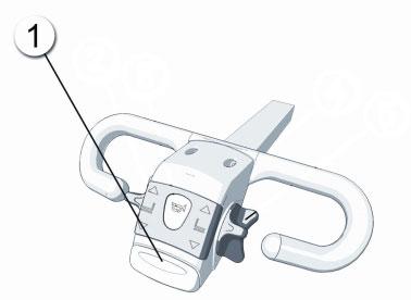
Figure 3.8. Safety button
38
Check the operation of the safety button by pressing it while driving the truck slowly in the direction of the tiller arm. If the safety button does not function properly, halt the maintenance process immediately and take the truck out of use until the safety button is fully operational.
Continue with this test only if the safety button of the truck is operational. Refer to Chapter 2 Operating the truck for information on the truck’s controls and driving.
1. Begin by taking hold of the tiller arm and lowering it from the upright position to the driving position. Do not lower it to the bottom position.
2. Use the accelerator on either side of the tiller arm to test the speed control. Move the accelerator gently in the forward direction.The truck should accelerate smoothly while the controller is moved. Reduce the speed from the accelerator and the truck should respond smoothly.
3. Test the reverse direction similarly. Accelerate in the forward direction once again and test reverse braking by moving the accelerator opposite to the direction of the movement.The truck should first decelerate and then begin to move in the opposite direction until the accelerator is released.
4. Test that the position sensor of the tiller arm operates by attempting to drive when the arm is in the upright and in the bottom position.The truck should not respond to the accelerator when the tiller arm is in these extreme positions.
5. Repeat the test by moving the tiller arm to the driving position, driving the truck slowly and both pressing the arm down to the bottom position and releasing it to the upright position. In both cases, the truck should stop.
6. Drive the truck both forward and backward, and test the steering by moving the tiller arm from side to side. Steering should be smooth throughout the available arc in both directions.
7. Test the horn by pressing the horn button on the tiller arm.
39
If any problems are encountered during this test, take the truck out of use until it is fully operational.
3.4.12.Testing the parking brake
The trucks are equipped with an automatic parking brake.The brake should be active when the main power is off and also when the main power is on unless the accelerator is moved to issue a driving command.Test the parking brake by trying to move the truck.When the brake is active, the truck should not move forward or backward.The parking brake only affects the drive wheel so that the other wheels are still free to turn.The tiller arm can also be freely moved from side to side while the parking brake is active.
Test the operation of the lifting hydraulics by lifting and lowering the forks. Refer to Chapter 2 Operating the truck for information on the truck’s controls.The forks should rise smoothly from the lowest position to the highest position.The forks should stop smoothly when reaching the upper position. If the forks hit the upper position at full speed, there may be a problem in the system. Refer to Chapter 6 Mechanical maintenance for information on mechanical maintenance.
3.5.Weekly maintenance
Like daily maintenance, weekly maintenance is important for keeping the truck in full working order.Weekly maintenance should be scheduled for a certain day of the week, so that the maintenance interval does not fluctuate.When weekly maintenance is due, complete all of the daily maintenance procedures first before continuing with the weekly maintenance procedures.
Before beginning, ensure that the main power of the truck is turned off. Open the main and top covers of the truck before commencing with the weekly maintenance procedures. Refer to Section 3.2 Maintenance guidelines for information on how to open the truck’s covers.
Should the weekly maintenance procedures reveal anything that affects the use or safety of the truck, the truck must immediately be taken out of use until it is restored to full working order.
40
3.5.1. Checking that fixing hardware and tube couplings are secure
Check that all accessible fixing hardware is securely fastened, and that there is no play between parts that should be firmly fixed. Check that all the couplings in the hydraulic system are tight.
3.5.2. Checking and cleaning the batteries and battery cabling
Open the battery compartment cover to access the batteries. Depending on the truck model and battery type, it may be necessary to open the fixing bracket and slide out the battery assembly from the compartment to gain better access.Visually check the condition of the battery cells. Check that all the battery cabling (both to the main poles and between cells) is securely fixed and in good condition, with all the insulators intact.
Over time, grime accumulates onto the batteries. Clean batteries weekly with a non-conductive and non-abrasive dry cloth. Never use water or any other cleaning agent when cleaning batteries or battery cells.Take precautions for handling lead-acid batteries, which contain a corrosive acid solution.Take care to not short-circuit a battery or cell connection.
3.5.3. Checking the amount of hydraulic fluid
If the forks and possible initial lift cannot be lifted to their topmost positions, there is an insufficient amount of hydraulic fluid in the system. If this is the case, lower the forks so that there is no pressure in the system and add hydraulic fluid into the tank to three-quarters (¾) of its capacity.
41
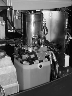
Figure 3.9. Hydraulic tank location
Refer to Section 3.9 Lubricant and fluid recommendations for fluid recommendations.When adding hydraulic fluid to the system, use only new and clean fluid, and uphold cleanliness during the operation so that contaminants are not introduced into the hydraulic system.Take appropriate precautions when handling hydraulic fluid, as it is harmful.
3.5.4. Checking the condition of identification plates and labelling
The main identification plate of the truck is located on the underside of the tiller arm. Check that it is firmly in place, undamaged and fully legible. If the plate is missing or cannot be read, a new one must be fitted. In addition to the identification plate, check that other labelling and markings, such as lifting points or any warnings, are in place and intact.
3.5.5. Cleaning the truck
Clean the truck at least once a week. Keeping the truck clean upholds safety and helps to maintain it in good working condition. If the truck is kept clean, it is also easier to notice possible damage or wear.
42
When cleaning the truck, take care not to let water or other fluids enter the main chassis or battery compartment. Never use a pressure washer to clean the truck. Use a dry and clean cloth when possible and use solvents only when necessary. If solvents are necessary, make sure that the chemicals will not harm the surface or component that is being cleaned.
3.6. Monthly maintenance
There is only one monthly maintenance procedure.
3.6.1. Lubricating the drive unit bearings
The bearings of the drive unit must be lubricated monthly. Open the main cover of the truck to gain access to the bearing.The bearing assembly to be lubricated sits above the drive motor and transmission assembly.The lubrication nipple should be used to lubricate the bearings.
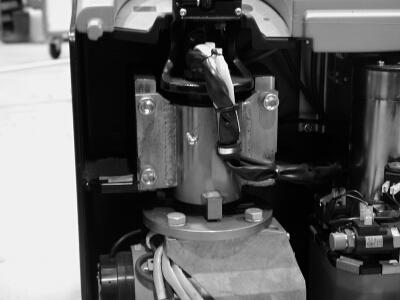
Figure 3.10. Lubrication nipple location
Use a grease gun to press the lubricant into the bearing assembly. Refer to Section 3.9 Lubricant and fluid recommendations for lubricant recommendations. After lubrication, move the tiller arm from side to side to distribute the lubricant evenly in the bearing assembly.
43
3.7. Semi-annual maintenance (after 600 hours of operation)
Semi-annual maintenance should be carried out either after half a year or after 600 hours of use, whichever is sooner. If the truck is equipped with an operating time meter, semi-annual maintenance is easy to schedule. If not, the operating time can be read using the console (refer to Chapter 4 Electrical operation and maintenance for more information on using the console). The semi-annual maintenance procedures should be carried out only by a trained professional.
3.7.1. Daily and weekly maintenance procedures
Before beginning the semi-annual maintenance procedures, both the daily and weekly maintenance procedures must be carried out as explained above.
Before continuing to the semi-annual maintenance procedures, ensure that the power to the truck is turned off.The procedures described below require that you first remove the main and top covers of the truck.
Visually check that all the main electrical connections and cabling of the truck from the battery to the drive and pump motors are in good working order.Take appropriate precautions for performing electrical maintenance.
Perform the check by starting from the battery connection and making your way to all the electrical components via the main fuses. Check that all connections are secure and that all cabling is in good condition. Pay attention to binding points and eyelets, as well as other locations where cables may come under stress during use.
Check the condition of the carbon brushes in the pump motor. The brushes must be changed when they have worn sufficiently. Contact your supplier for the correct replacement components.
44
WARNING!
Disconnect the main battery connector before attempting any maintenance on the pump motor.
3.7.3.1. 1,000 kg capacity trucks
Checking the wear of the pump motor carbon brushes on the 1,000 kg capacity truck requires that the pump motor – hydraulic tank assembly is removed from the truck chassis. After removal, follow the steps given below.
To check the wear of the pump motor carbon brushes:
1. Before opening the pump motor, mark the position of the different components of the motor unit for reference during reassemly.
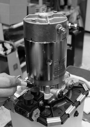
Figure 3.11. Marking the position of the motor components
2. Unscrew the two fixing screws on the top cover of the pump motor and lift the top cover carefully off the motor.
3. Uncrew the connection bridge fixing screws and carefully remove the connection bridge.
45


