13 minute read
warn.temp.invert
3. Press the upward arrow key to change the value to “1”.
4. Press the Enter key to initiate the programming procedure.
5. During the 15-second programming period:
a. Move the proportional control smoothly to the maximum lifting value.
b. Keep it held for one second.
c. Move it to the maximum lowering value.
d. Keep it held for one second.
e. Return it to the neutral value.
6. If the procedure was successfully completed, the parameter value returns to “0” automatically.
The pump motor is disabled while the programming procedure is carried out.
NOTE
4.4.3. Fault codes
When a fault occurs in the HCU, it is disabled.The fault code can be read by opening the truck's main cover and reading the code from the HCU status LED.The status LED displays the code by flashing in a sequence.The number of pulses in the sequence indicates the fault. For example, a repeating sequence of five pulses and a pause indicates error 2.
The possible fault codes:
• Error 2: New software version
This error appears only when a new software version is being loaded into the controller.
• Error 4: Low battery voltage
This fault is triggered if the HCU detects a drop in the battery voltage. It can indicate a problem in the batteries or supply cables. Check the condition of the battery and the supply cables.The fault can be reset by switching the controller supply off and then on.
107
• Error 5: Battery overvoltage
This fault is triggered when the HCU detects a too high voltage at its supply terminals. Check the connections between battery and the controller. If the cause cannot be located, replace the HCU.
• Error 6: Unrealistic lift/lower curve parameters
This fault indicates that there is a problem with the parameters that control lifting and lowering.Verify that the parameters are within the allowed range.
• Error 7: Unrealistic option curve parameters
This fault indicates that there is a problem with the parameters that control an optional component.
• Error 8: Control active at power-up
This fault indicates that there was an error in the start-up sequence. It can result from a switch or potentiometer being active while the HCU powers up. Release all controls to their neutral positions and restart the truck.
• Error 9: More than one function active
This fault indicates that more than one function is active simultaneously. Check that the HCU is not receiving more than one input at a time.
• Error 10: Error in sequential program
This fault indicates a problem with the internal sequential program. If the fault persists, the HCU must be replaced.
• Error 11: Digital output error
This fault indicates a problem with the digital outputs. If the fault persists, the HCU must be replaced.
• Error 14: EEPROM fault
This fault indicates a problem with the internal EEPROM. If the fault persists, the HCU must be replaced.
108
4.5. Electrical maintenance and repairs
This section provides instructions for specific maintenance procedures.These tasks are not part of the regular maintenance schedule.They are performed when needed. Refer to Section 3.1 Safety guidelines and preparation and Section 3.2 Maintenance guidelines for information on safety and preparation for maintenance tasks.
If other (than those examined below) electrical components fail, contact your supplier or local technical support for replacement parts and instructions. If you have a specific electrical maintenance problem that is not answered here or in another part of the manual, contact your supplier or technical support.
4.5.1. Battery maintenance
Before performing battery maintenance, take safety precautions appropriate for handling lead-acid batteries and battery fluid. A truck battery carries a considerable amount of stored electrical energy.When handling a battery, battery assembly or battery cell, insulate all the electrical contacts to minimise the risk of a short circuit. Be careful with conductive tools and equipment when working near batteries. Lead-acid batteries contain a corrosive acid solution.Wear appropriate protective gear such as protective clothing, gauntlets and eyewear. Refer to Chapter 3 Regular maintenance for information on regular battery maintenance procedures. Contact technical support for current information on servicing truck batteries and acquiring a new battery or battery assembly.
The truck's battery assembly consists of 12 wet lead-acid battery cells and has a nominal voltage of 24 V. Depending on the model, a truck can accommodate power sources with capacities between 160 and 345 Ah.The battery assembly is connected to the truck’s electrical system via connector X1. Refer to Section 4.1 Electrical operation for more information on the electrical connections and operation of these trucks.
109
110 Figure 4.5. Battery assembly
When you suspect that a battery cell or the entire battery assembly is not functioning optimally, check the state of the cells in the assembly by measuring their specific gravity.This measurement provides more reliable information about the condition of a cell than, for example, measuring its voltage. Always refer to the maintenance instructions issued by the manufacturer or supplier of the battery cell or battery assembly. As a guideline, however, the specific gravity measurement of a fully-charged battery cell should be 1.28 to 1.30 at 30°C. A cell is about half-charged if it measures 1.20 and empty at 1.15 or below.
If a battery cell needs to be replaced, refer to the maintenance instructions issued by the cell manufacturer. Remember to use a cell that is identical to the original one in electrical characteristics, size and weight. In circumstances in which several cells are performing badly, it may be wise to replace the entire battery assembly. It is very important that all the characteristics, especially the weight of the new battery assembly is identical to the original one, so that the truck’s usage safety is not affected.The truck’s identification plate indicates the minimum weight of the battery.
Be careful when replacing the battery assembly, as it is very heavy. Use a sufficiently powerful crane or truck to lift the
assembly from its marked lifting points. Never lift the assembly from any other points.When preparing the assembly for lifting, insulate the battery cell contacts to protect against short circuits.
4.5.2. Fuses
The truck's fuses do not require regular checks.They need to be replaced only if they have blown. Never operate a truck with a blown fuse. Replace the fuse before continuing to use the truck. When fuses need to be changed, always replace them with identical components. Never use a fuse of another rating than that recommended by the manufacturer.
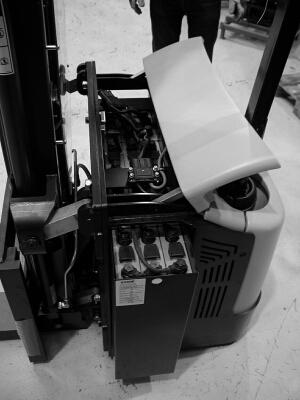
The standard truck has two main fuses and an auxiliary fuse in the controller.To access the fuses, open the truck’s main cover.
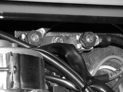
Figure 4.6. Example of the two main fuses
On the electrical schematic diagram, the main fuses are marked as 1F1 and 2F1 (zones 20 and 24 on page 1). Fuse 1F1 supplies the positive battery feed to the traction controller. It is rated at 100 A on all truck models. Fuse 2F1 supplies the positive battery feed to the K1 pump motor contactor. It is rated at 150 A on all truck models.
The auxiliary controller fuse is mounted in the controller, but can be accessed from the outside.The auxiliary fuse is marked as A1F1 in the electrical schematic diagram (zone 15 on page 2). It is rated at 5 A.
111
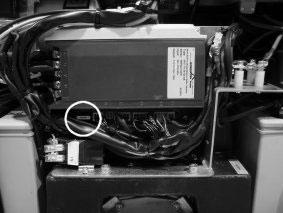
Figure 4.7. Auxiliary controller fuse
If the truck is equipped with a hydraulic control unit (HCU), it has an individual fuse.The fuse is marked as A2F1 in zones 29-30 on page 2 of the electrical schematic diagram.
4.5.3. Replacing a controller
A controller in the truck may encounter an internal fault, which cannot be fixed from the outside. In this case, it is best to replace the entire controller. Contact your supplier or technical support for information on obtaining up-to-date documentation and parts for the truck.The truck cannot be used with a faulty controller.
Turn the main key switch off and disconnect the battery before attempting any maintenance procedures on the controller.When disconnecting the controller, remember to start by removing the positive supply connection first and the negative connection last. When connecting a new controller, connect the negative supply connection first and finish with the positive connection. Pay attention to the polarity markings on the controller, as polarity inversion will damage it. Contact technical support for the latest information regarding controller replacement.
112
NOTE
The parameters of the replacement controller must be reprogrammed for the application.
The accelerator module in the tiller arm head may require replacement during the truck’s operating life.The tiller arm head assembly contains the main control devices needed by the operator to use the truck. Its main component is the accelerator. It also houses the lifting controls, the brake release button, the horn button and the safety button. Refer to Chapter 2 Operating the truck for more information on the truck’s control devices. WARNING! Disconnect the battery connector before beginning.
To replace the accelerator module:
1. Begin by locating the two fixing screws on the underside of the head assembly and the two screws on the topside of the assembly. Open the four screws using a 5 mm Allen key.
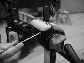
Figure 4.8. Main fixing screws at the back of the tiller arm head assembly
113
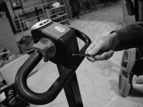
Figure 4.9. Main fixing screws in front of the tiller arm head assembly
2. After removing the screws, lift the top section upwards from the edge containing the safety button. Be careful with the end closer to the arm, as lifting it might stress the internal wiring.
114
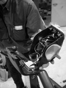
Figure 4.10. Opening the assembly
3. Disconnect the connector from the accelerator module.
4. Remove the accelerator controls from both sides of the assembly by unscrewing them from the axle.Take care not to lose the spring washers.
5. Loosen the two fixing screws holding the accelerator module with a 4 mm Allen key.The screws do not have to be removed, loosening is sufficient.
6. Remove the safety switch carefully by prying it with a flat-head screwdriver.
7. Install the new accelerator module.
8. Replace the safety switch.
9. Tighten the accelerator module fixing screws.
10.Replace the accelerator controls to the assembly. Note the position of the controls: one of the three wings of both
115
controls should point in the direction of the arm, that is, downwards when the arm rests in the upright position.
11.Connect the accelerator module connector.
12.Reposition the top section of the assembly on to the bottom section.
13.Tighten the four fixing screws.
Once the accelerator module has been replaced, it should be tested. Begin by programming the voltage range of the accelerator to the truck’s traction controller. For more information on this procedure, refer to Section 4.3.2.38 Parameter 251: Program throttle. After this procedure, thoroughly test the operation of the tiller arm head controls before returning the truck to normal use.
116
6. Mechanical maintenance
This chapter presents the mechanical maintenance procedures not covered in Chapter 3 Regular maintenance. Refer to Section 3.1 Safety guidelines and preparation and Section 3.2 Maintenance guidelines for information on safety and preparation for maintenance tasks. Refer to Chapter 2 Operating the truck for operating instructions.
6.1. Replacing wheels
A truck has three wheel types: drive, load and castor wheels. Check all the wheels on a truck for damage and wear.The wheels should wear evenly and there should be no flats or holes in the wear surface.The wheels should also turn smoothly on their axles and there should not be play in the bearings. Even wear can be checked by driving the truck on a smooth surface to test that all the wheels turn and the truck rides smoothly. If a wheel or a bearing has sustained damage that affects use or if its surface has worn completely, it should be replaced.
To replace a truck wheel, follow the instructions given below. Never work under the truck if it is supported only by a jack.
WARNING!
6.1.1. Replacing the drive wheel
The drive wheel is located immediately under the tiller arm anchoring point and supports a considerable portion of the truck’s weight.The drive wheel is used to propel and steer the truck. It is attached to the drive motor via the transmission.The tiller arm is used to turn the drive wheel when steering the truck.
To replace the drive wheel:
1. Open the truck's main cover by unscrewing the two fixing screws.
2. Turn the drive wheel using the tiller arm so that the fixing screws of the wheel can be reached.
3. On 1,600 kg capacity trucks, remove the five wheel fixing screws with a 19 mm wrench. On 1,000 and 1,200 kg capacity trucks, remove the ten wheel fixing screws with a
147
5 mm Allen key. Do not remove the two countersunk screws, as they hold the planet gear rim in place.
4. Lift the truck from under the chassis using a suitable jack so that the drive wheel is lifted off the supporting surface.
5. Remove the old drive wheel.
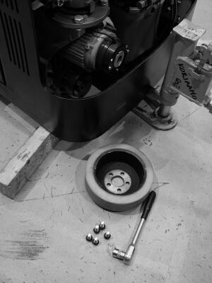
Figure 6.1. Drive wheel of a 1,600 kg capacity truck
6. Attach the new drive wheel.
7. Replace the main cover and test the operation of the drive unit.
6.1.2. Replacing the load wheels
The load wheels are located near the ends of the forks.Their main purpose is to support the weight of the load. Depending on the truck model, there is either a single or a double load wheel in each fork.
To replace single load wheels:
1. Loosen the locking pin from the axle using a 5 mm pin punch.
The locking pin is located on the outside end of the axle.
148
2. Raise the forks and lift the truck slightly with a jack.
3. Remove the locking pin from the axle.
4. Remove the load wheel axle.
5. Replace the load wheel and reattach the axle and the locking pin.
To replace double load wheels:
1. Lift the truck using a jack. Place supporting brackets under the truck.
2. Remove the axle bolt using a 8 mm Allen key on both ends of the bolt.
3. Replace the load wheel and reattach the axle bolt.
6.1.3. Replacing the castor wheel
The supporting castor wheel is located under the main chassis opposite to the drive wheel.The castor wheel balances the truck and turns automatically to follow the direction of travel.
To replace the castor wheel:
1. Lift the truck using a jack. Place supporting brackets under the truck.
2. Remove the axle bolt using a wrench on both ends of the bolt.
3. Replace the castor wheel and reattach the axle bolt.
6.2. Replacing the tiller arm gas spring
This section gives instructions on how to replace the gas spring of the tiller arm.The purpose of the gas spring is to return the tiller arm automatically to the upright resting position. It is a safety device, which must always be fully operational.
To replace the gas spring:
1. Remove the cover from the base of the tiller arm.
149
2. Remove the ball joints from both ends of the gas spring using a 13 mm wrench.
3. Replace the gas spring.
4. Attach the ball joints to the tiller arm.
5. Reattach the cover to the base of the tiller arm.
6. Test the operation of the tiller arm.
Figure 6.2. Replacing the tiller arm gas spring
6.3. Lever system maintenance
The lever system is present only on trucks with initial lifting functionality.The system is composed of levers and the initial lifting cylinder between the main chassis and the mast assembly, and push rods under the forks.They operate to lift the mast and fork assembly evenly when initial lifting is used.The following procedures provide instructions for disassembling the system for maintenance purposes.
150


