1 minute read
Hydraulic System


Hydraulic System
Design
A 80V / 23,5 kW threephase motor is used to drive the pump.
The thermal gauge for temperature control is sealed in a field coil, the speed sensor is located in the sensor bearing.
Motor overtemperature is displayed via an indicated in the multi-function display.
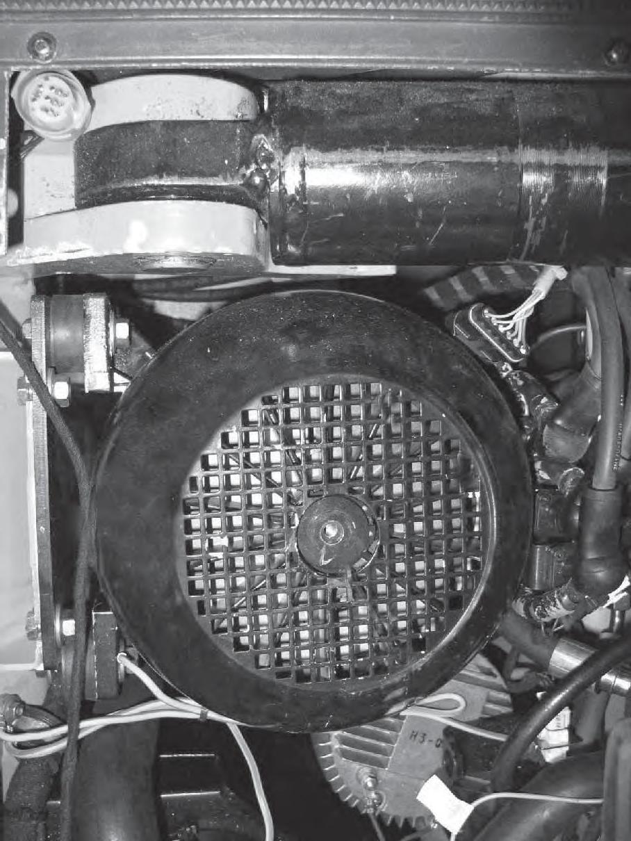
fi g. 80
Item Description Item Description
1 Pump motor 5 Measurement port 2 Cross coupling 6 Pressure fi lter 3 Hydraulic pump 4 Hydraulic oil reservoir 7 Sensor bearing and temperature gauge connector
Hydraulic unit disassembly/assembly
• Park the truck securely • Fully lower the load handler
Set the main switch and key switch “ • OFF”. • Disconnect the battery
STOP
Depressurise the hydraulic lines before disassembly.
• Undo the motor connections
• Turn the eye bolt in the rotor shaft (8)
• Attach the chain pulley to the overhead guard and gently pull the hydraulic unit. Undo the 2 screws (9) on the mounting plate
• Remove the potential compensation wire (green/yellow)
• Remove the temperature transmitter and the sensor bearing
• Disassembly the suction hose from the reservoir and seal it
• Seal the reservoir
• Disassemble the pressure hose from the pump and seal it
Collect any escaping oil and dispose of it in accordance with environmental regulations.
• Using the chain pulley lift the hydraulic unit out of the truck and place it next to the truck
Assembly is the reverse order
! Note cross coupling assembly position
Pump groove depth: 6,5 mm - engine groove depth: 9,5 mm Pre-fill the suction hose before connecting. To bleed the hydraulic system, apply the pump motor at low speed.
8
9
fi g. 81