6. HYDRAULIC SYSTEM
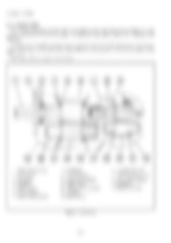
6.1.1 FRONT PUMP Note: For the front pump of trucks whose serial number is lower than those shown in Figure 6.1, refer to "6.1.2 REAR PUMP" on the next page. Its operation is the same as that of the 1st pump in this paragraph. The front pump is a double gear pump and driven by the PTO device of the transmission. The 1st pump sends oil from the oil tank to the control valve while the 2nd pump sends oil to the accumulator of the brake system. The design of the front pump as shown below.
1. DRIVE GEAR (1ST) 2. SNAP RING 3. OIL SEAL 4. GASKET 5. SIDE PLATE 6. VALVE BODY 7. DRIVE GEAR (2ND)
8. BUSHING 9. VALVE BODY 10. 3-LETTER GASKET 11. SIDE PLATE 12. DRIVEN GEAR (2ND) 13. GASKET 14. STEEL BALL
Fig. 6.1 Front Pump
- 84 -
15. ADAPTER PLATE 16. DRIVEN GEAR (1ST) 17. 3-LETTER GASKET 18. BUSHING 19. FRONT COVER.

