Wire Description Chart
MODULE IDENTIFIER (MID) LIST 26
SENR5718 AUGUST 1992
Module Computerized Monitoring System (CMS)
27
HARNESS CONNECTOR LOCATION CHART
FMI No. 0 1 2 3 4 5 6 7 8 9 10 11 12 13
Machine Connectors Location
Failure Description Data valid but above normal operational range. Data valid but below normal operational range. Data erratic, intermittent, or incorrect. Voltage above normal or shorted high. Voltage below normal, or shorted low. Current below normal or open circuit. Current above normal, or grounded circuit. Mechanical system not responding properly. Abnormal frequency, pulse width, or period. Abnormal update. Abnormal rate of change. Failure mode not identifiable. Bad device or component. Out of calibration.
40 Contacts
4
13
7 15
11
9
20
4
8
23
10 1
*
4
17
2
3
E
21
C
19
5
A 1
7
11
2
16
1
12
1
3
13
18
D
25 Contacts
9
B
6
2
5
14
12
20 Contacts
22
14 8 10
1
24 2
6
3
* 14 Contacts
5 6 3
2
12 Contacts 1 7
7
Component Identifiers (CID) List CID 096 100 110 168 177 248 270 271 324 600 601 621 622 623 626 627 628 631 632 633 634 635 637 653
Component Fuel Level Sensor Engine Oil Pressure Sensor Engine Coolant Temperature Sensor Electrical System Voltage Power Train Oil Temperature Sensor Data link Harness Code Action Alarm Action Lamp Hydraulic Oil Temperature Sensor Brake Air Pressure Sensor Downshift Switch Upshift Switch Direction Switch Lock Switch Parking Brake Switch Quickshift Switch Clutch 1 Solenoid (Reverse) Clutch 2 Solenoid (Forward) Clutch 3 Solenoid (Speed) Clutch 4 Solenoid (Speed) Clutch 5 Solenoid (Speed) Start Relay Transmission Control
C
8
8
B 6
A 8
6
12
5
1
6 18
10 2 D
1
9
3
3
20 23
8 Contacts
13
13
14 10 11
8
9
4
21
15
* *
5
Machine Connectors Location 9
D-7
10
E-3
11
C-6
12
A-11 6 Contacts
D-8
* *
C-10
*
E-6
*
F-6
*
A-10
3
D-9
7
F-9
13
A-7
3
E-7 4 Contacts
B-9
14 3
D-6 D-5
* *
C-4
12
C-4
Harness And/Or Components
Schematic Location
A - 9U1947 K - 9U1894 F - 9U2063 J - 9U2064 F - 9U2063 J - 9U2064 P - 4E8279 YY - 9U4740 M - 9U2275 Shutdown Control P - 4E8279 Front Wiper Motor P - 4E8279 Voltage Converter R - 4E8229 Rear Wiper TT - 713312 Payload Display A - 9U1947 E - 9U1953 P - 4E8279 R - 4E8229 X - 4E9103 Y - 4E9848 JJ - 1007425 RR - 713311 JJ - 1007425 XX - 1007424 B - 9U1948 Service Plug D - 9U1952 Fuel Sensor P - 4E8279 Hydraulic Hand Sw P - 4E8279 Service Plug
C-11 B-2 C-2 C-3 A-10 C-3 C-6 E-5 A-2 A-9 D-5 F-3 A-8 A-2
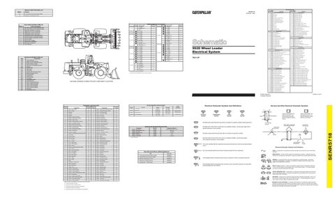
992D Wheel Loader Electrical System
A-3
RD
BAT
500
BR
WIPER - FRONT (PARK)
102
BU
HEAD LAMP
501
GN
WIPER - FRONT (LO)
105
BR
KEY SW
502
OR
WIPER - FRONT (HI)
106
WH
AUX CKT
503
BR
WIPER - REAR (PARK)
107
WH
ENC SHUT - DOWN FIRE SUPPR
504
YL
WIPER - REAR (LO)
109
OR
ALT OUTPUT (+) TERM.
505
BU
WIPER-REAR (HI)
112
PU
MAIN POWER RELAY OUTPUT
506
PU
WASHER - FRONT
113
OR
OPR MON PANEL B+ SWITCHED
507
WH
WASHER - REAR
114
GN
WARNING HORN (FORWARD)
508
PU
RADIO SPEAKER - LEFT
118
GY
AUX CKT
509
WH
RADIO SPEAKER - LEFT (COMMON)
124
GN
A/C
511
BR
RADIO SPEAKER - RIGHT
128
PK
AUX CKT
512
GN
RADIO SPEAKER - RIGHT (COMMON)
129
BU
AUX CKT
513
OR
A/C COMPRESSOR/REFRIGERANT PRESS. SW
140
BU
AUX CKT
515
GY
BLOWER MOTOR (HI)
150
OR
EUI B+ SWITCHED
516
GN
BLOWER MOTOR (MEDIUM)
164
WH
HYDRO CONT TO WTL POWER TRAIN CTRL
517
BU
BLOWER MOTOR (LO)
519
PK
THERMOSTAT TO REFRIGERANT PRESS. SW
200
BK
MAIN CHASSIS
520
WH
OPR A/C SW TO THERMOSTAT/FUSE
201
BK
OPR MOO PANEL CMS
592
BU
DC/DC CONVERTER POWER OUTPUT
202
BK
XMSN CONT
A513
PK
DC/DC CONVERTER MEMORY OUTPUT
203
BK
CHASSIS DIAGNOSTIC
A515
BR
BLOWER MOTOR #2 (HI)
207
BK
STARTER DIAGNOSTIC
A517
OR
BLOWER MOTOR #2 (LO)
250
BK
PAYLOAD MON - CUSTOMER GROUND
251
BK
PAYLOAD MON - SYSTEM GROUND
600
BR
DASH LAMP BASIC
270
BK
CMS IDENT CODE 0
604
OR
STOP LAMP
271
BK
CMS IDENT CODE 1
607
PK
FLOOD LAMP - FRONT
272
BK
CMS IDENT CODE 2
610
OR
HEAD LAMP BASIC
273
BK
CMS IDENT CODE 3
615
YL
CAB FLOOD LAMP/ROPS
274
BK
CMS IDENT CODE 4
616
BU
BUCKET FLODD LAMP/BOOM FLODD LAMP
280
BK
XMSN CONT IDENT CODE 4
637
GN
LCL LAMP
281
BK
XMSN CONT IDENT CODE 5
644
OR
BRIGHTNESS ADJUST
290
BK
SERVICE
291
BK
CLEAR
710
GN
XMSN SPEED PICKUP SIGNAL
751
GN
XMSN SHIFT SOL NO.1 OR 3
301
BU
STARTER NO.1 SOL
752
YL
XMSN SHIFT SOL NO.2
302
OR
STARTER NO.1 RESISTOR TO DIAGNOSTIC
754
BU
XMSN SHIFT SOL NO.3 OR 1
304
WH
STARTER RELAY NO.1 OUTPUT
755
OR
XMSN SHIFT SOL NO. 4 OR 5
306
GN
STARTER RELAY COIL TO NEUT START SW OR KEY SW
761
GY
LIFT KICKOUT SOL SW
307
OR
KEY SW TO NEUT START SW
762
YL
BUCKET POSITIONER SOL SW
308
YL
MAIN POWER RELAY COIL
818
BR
SERIAL DATA (TRANSMIT)
310
PU
START AID SW TO START AID SOL
819
GY
SERIAL DATA (RECEIVE)
311
WH
START AID SOL TO TEMP SW
820
BU
TRANSMIT KEY
312
PK
STARTER NO.2 SOL TO RESISTOR
863
BU
PAYLOAD MON TRANSMIT LCD OUT
313
GY
STARTER NO.2 RESISTOR TO DIAGNOSTIC
864
BR
PAYLOAD MON CLOCK LCD OUT
314
PU
STARTER RELAY NO.2 OUTPUT
865
GY
PAYLOAD MON LATCH LCD OUT
321
BR
BCKP ALARM LAMP TRAVEL ALARM
900
PU
XMSN SHIFT SOL NO.5 OR 4
322
GY
WARNING HORN (FORWARD)
944
OR
CMS COMM +
326
PU
KEY SW -C" TERM.
945
BR
CMS COMM -
327
PK
SHUTDOWN SOL
975
WH
CST AUTOSHIFT - SOL RETURN
338
PK
FLOOD LAMP RELAY COIL
976
OR
RIDE CONT SOL
D721
WH
WTL XMSN CONT TOROUE LIMIT INPUT
Lighting Circuits
Control Circuits
Basic Machine Circuits
E-8 F-7
101
Ground Circuits
7MJ1-UP
C-3
A-5 F-4 D-4 F-5
Monitoring Circuits
A-2
*= Connector is located at the component.
19
17
* *
16
14 4
2
7
E
12
11
22
24
Schematic Location
B - 9U1948 Transmission Cont P - 4E8279 CMS A - 9U1947 P - 4E8279 C - 9U1951 M - 9U2275 A - 9U1947 B - 9U1948 A - 9U1947 C - 9U1951 B - 9U1948 Q - 4E8277 RR - 713311 TT - 713312 M - 9U2275 Diagnostic Connector RR - 713311 Payload Monitor Cont B - 9U1948 N - 8E7954 A - 9U1947 F - 9U2063 A - 9U1947 H - 9U1954 A - 9U1947 M - 9U2275 A - 9U1947 P - 4E8279 P - 4E8279 R - 4E8229 P - 4E8279 S - 9U0785 P - 4E8279 S - 9U0785 P - 4E8279 T - 4E7243 Q - 4E8277 Shifter Control R - 4E8229 Front Wiper Sw QQ - 9U4430 Radio TT - 713312 Payload Display
* 37 Contacts
Harness And/Or Components
Machine locations are repeated for connectors located close together.
MACHINE HARNESS CONNECTOR AND COMPONENT LOCATIONS
Description Accessory Circuits
Power Distribution Circuits
Electronic Transmission Control
Failure Mode Identifiers (FMI) List
WIre Wire Number Color
Description
403
GN
ALTERNATOR (R) TERM.
D726
PU
WTL XMSN CONT STEERING CONSOLE SW 1
410
WH
OPR MON ACTION ALARM
D727
YL
WTL XMSN CONT STEERING CONSOLE SW 2
411
PK
OPR MON ACTION LAMP
D728
BU
WTL XMSN CONT FORWARD SW TO GND
412
BU
OPR MON COOLANT FLOW
D729
GY
WTL XMSN CONT REVERSE SW TO GND
417
GY
PRIMARY STER SW
D730
GN
WTL XMSN CONT SPEED 1 SW TO GND
419
YL
OPR MON PARKING BRAKE
D731
WH
WTL XMSN CONT SPEED 2 SW TO GND
426
BR
OPR MON POWER TRAIN OIL FILTER
D732
YL
WTL XMSN CONT SPEED 3 SW TO GND
432
PK
OPR MON BRAKE PRESS. (OIL)
D733
BR
WTL XMSN CONT SPEED 4 SW TO GND
441
OR
ENG COOLANT TEMP GAGE
D734
PU
WTL XMSN CONT NEUTRAL SW TO GND
442
GY
HYD SYSTEM TEMP GAGE
D735
PK
WTL XMSN CONT PARK BRAKE LEVER SW TO GND
443
YL
POWER TRAIN TEMP GAGE
D736
GN
WTL XMSN CONT LOCKUP ENABLE SW
447
PK
FUEL LEVEL GAGE
D756
YL
CMS PARK BRK - LVR STEER
464
GY
OPR MON PANEL ENG OIL PRESS. SENSOR
D757
OR
TRANSMISSION NEUTRALIZER SW #2
A401
YL
ELECTRICAL SYSTEM NO.1 VOLTAGE
D758
PU
OUICKSHIFT SW (N.C.) LEVER STEER
8412
YL
WTL PMS LIFT POS SENSOR
D759
WH
QUICKSHIFT SW (N.O.) LEVERSTEER
8413
PU
WTL PMS LIFT CYL PRESS. SENSOR
8414
OR
WTL PMS NORM/CALIBRATE OUT
8415
PK
WTLPMSCLEAR/CHGOUT
8416
WH
WTL PMS REWEIGH SW IN
8417
YL
WTL PMS STORE SW IN
8475
OR
OPR MON PARK BRAKE PRESS. SW
Printed in U.S.A.
© 1992 Caterpillar All Rights Reserved
OFF MACHINE SWITCH SPECIFICATIONS
COMPONENT LOCATION CHART Machine Location
Component
Schematic Location
F-3
14
Sensor - Hydraulic Oil Temperature (CMS)
A-8
Alarm - Backup
D-12
15
Sensor - Uft Cylinder Pressure (PMS)
2
Alternator
E-11
16
3
Batteries
A-12
17
Component
A
Alarm - Action (CMS)
1
Schematic Machine Location Location
Coolant Temp
D-1
3E6452
Brake Press
Sensor - Uft Position (PMS)
D-1
4E4456
Neutralizer Press
Sensor - Power Train (CMS)
E-11
9X7781
Trans Filter Bypass
4
Batteries
F-12
C
Shifter - Lever Steer
Breaker - Alternator (80 Amp)
B-11
2
Solenoid - A/C Clutch
B-11
5
Breaker - Blower Motor (15 Amp)
A-6
B
Solenoid - Bucket Float
B-4
5
Breaker - Seat (15 Amp)
A-6
B
Solenoid - Bucket Positioner
B-4
D
Breaker - Engine Shutdown (15 Amp)
A-11
18
Solenoid - Engine Shutdown
E-11
D
Breeker - Key Switch (10 Amp)
B-10
19
Solenoid - First Gear (Clutch 5)
F-8
D
Breeker - Main Power (80 Amp)
B-10
19
Solenoid - Forward (Clutch 2)
F-9
5
Breeker - Running Lamps (10 Amp)
B-10
B
Solenoid - Uft Kickout
B-4
D
Control - Engine Shutdown
A-10
19
Solenoid - Reverse (Clutch 1)
F-8
B
Control - Payload Monitor (PMS)
D-9
19
Solenoid - Second Gear (Clutch 4)
F-8
E
Control - Transmission
D-7
20
Solenoid - Start Aid
F-4
D-10
B
Converter - Voltage
C-6
19
Solenoid - Third Gear (Clutch 3)
A
Display - Payload Measurement System (PMS)
B-3
21
Solenoid - VCTC Valve
E-10
5
Fuse Holder
A-6
D
Switch - Battery Disconnect
D-11
5
Fuses (10 Amp)
A-6
C
Switch - Blower
E-4
5
Fuses (15 Amp)
A-5
E
Switch - Brake Pressure
F-8
6
Horn - Forward
B-2
22
Switch - Bucket Positioner
B-1
7
Horn - Forward
E-1
A
Switch - CMS Brightness Adjustment
C-4
A
Lamp - Action (CMS)
F-3
23
Switch - Coolant Flow (CMS)
F-11
A
Lamp - VCTC Indicator
D-3
12
Switch - Coolant temperature
F-11
B
Meter - Service
E-4
B
Switch - Flood Lamp
C-4
A
Monitor - Computerized System (CMS)
E-3
B
Switch - Floor Blower
D-4
C
Motor - Blower
E-4
C
Switch - Forward Horn
D-3
C
Motor - Floor Heater Blower
B-2
C
Switch - Front Wiper
D-4
5
Motor - Front Washer
A-7
B
Switch - Hydraulic Hand (VCTC)
A-3
C
Motor - Front Wiper
C-3
B
Switch - Key Start
C-4
5
Motor - Rear Washer
A-7
24
Switch - Uft Kickout
C-1
C
Motor - Rear Wiper
E-6
C
Switch - Neutralizer Umit
F-3
8
Motor - Starter
D-10
B
Switch - Neutralizer Override
B-4
9
Motor - Starter
D-11
E
Switch - Neutralizer Pressure
C
Radio
F-5
E
Switch - Parking Brake
D
Receptacle - Auxiliary Start
B-12
E
B
Relay - Flood Lamp
A-5
C
D
Relay - Main Power
B-10
C
Switch - Rear Wiper
E-4
D
Relays - Start
A-10
2
Switch - Refrigerant (AIC)
B-11
C
Resistor - Blower Speed
E-5
B
Switch - Reweigh (PMS)
A-3
8
Resistor - Starter Diagnostic
D-10
B
Switch - Running Lamp
D-4
9
Resistor - Starter Diagnostic
D-11
B
Switch - Start Aid
C-4
D
Resistor - System Voltage Diagnostic (CMS)
A-9
C
Switch - Steer Laver Lock
F-4
F-9
Resistor - Blower Speed Resistor - Starter/Diagnostic Conn Solenoid - A/C Clutch Solenoid - Engine Shutdown Solenoid - Start Aid Solenoid - Transmission Solenoid - VCTC Valve
9X4383 3E7842 7T8600 9X1413 3E6333 3E3748 4V1222
Overall 3.0 ± .15; Tap 1.0 ± .05 150.0 ± 7.5 14.4 ± 0.6 3.7 ± 0.4 6.0 8.5 41.5 ± 4.2
¹ At room temperature.
RELATED ELECTRICAL SERVICE MANUALS Title
F-8
Starting Motor;
SENR3860
Sensor - Engine Oil Pressure (CMS)
E-11
A
Switch - Primary Steering Flow (CMS)
B-10
12
Sensor - Engine Speed (CMS)
F-10
C
Switch - Thermostat
E-5
13
Sensor - Fuel Level (CMS)
F-8
E
Switch - Transmission Filter (CMS)
F-11
Level Symbol
Flow Symbol
Typical representation of a Deutsch connector. The plug contains all sockets and the receptacle contains all pins.
Receptacle
Plug
Pin or Socket Number
Typical representation of a Sure-Seal connector. The plugand receptacle contain both pins and sockets.
Wire, Cable, or Harness Assembly Identification
Normally open switch that is closed due to an applied condition, and will open again with a specific decrease in that condition.
Component Part Number
Single Wire Connector C
A
A 325-PK-14
AA 1
Normally closed switch that will open with an increase of a specific condition. Pin
9X-1123 325-PK-14
Wire Color
Socket
2
200-BK-14
Circuit Number Identification
Wire Gauge
50-MT Series
FUSE - A component in an electrical circuit that will open the circuit if too much current flows through it.
No circle indicates that the wire cannot be disconnected from the component.
Form No.
C-3
11
Temperature Symbol
Electrical Schematic Symbols And Definitions
Switch - Parking Brake Pressure
F-8
Pressure Symbol
1 2
1 2
T
The circle indicates that the component has screw terminals and a wire can be disconnected from it.
Switch - Quickshift
A-3
AA 1
Normally closed switch that is open due to an applied condition, and will close again with a specific decrease in that condition.
SENR2947
Switch - Stop Lamp
Normally Open
Resistance (Ohms) 1
Starting And Charging Systems
Switch - Store (PMS)
A
Contacts A-B (N.O.) Contacts A-C (N.C.) Normally Closed
Part No.
F-8
E
Harness And Wire Electrical Schematic Symbols
Normally Closed
RESISTOR AND SOLENOID SPECIFICATIONS Component
SENR5704
B
Electrical Schematic Symbols And Definitions
Normally open switch that will close with an increase of a specific condition (temp-press-etc.).
Electronic Transmission Control
D-5
Normal Condition
2
F-8
F-11
E - Components located in rear compartment under the platform.
27º C MIN (80º F MIN) 6890 ± 345 kPa (1000 ± 50 psi) 690 ± 105 kPa (100 ± 15 psi) -
SEHS5704
Sensor - Engine Coolant (CMS)
D - Components located in the relay panel.
38 ± 3º C (100 ± 5º F) 8270 kPa MAX (1199 psi MAX) 790 ± 140 kPa (114 ± 20 psi) 210 ± 70 kPa (30 ± 10 psi)
Payload Measurement System (PMS) .
Seat - Air Suspension
C - Components located in the operator's compartment.
Deactuate
SENR5247
C
B - Components located in the right console.
Actuate
Computerized Monitoring System (CMS)
10
A - Components located in the dash.
Function
3E6425
D
Machine locations are repeated for components located close together.
Part No.
REED SWITCH - A switch whose contacts are controlled by a magnet. A magnet closes the contacts of a normally open reed switch; it opens the contacts of a normally closed reed switch.
This indicates that the component has a wire connected to it that is connected to ground.
T
This indicates that the component does not have a wire connected to ground. It is grounded by being fastened to the machine.
SENDER - A component that is used with a temperature or pressure gauge. The sender measures the temperature or pressure. Its resistance changes to give an indication to the gauge of the temperature or pressure. RELAY (Magnetic Switch) - A relay is an electrical component that is activated by electricity. It has a coil that makes an electromagnet when current flows through it. The electromagnet can open or close the switch part of the relay. CIRCUIT BREAKER (C/B) - A component in an electrical circuit that will open the circuit if too much current flows through it. This does not destroy the circuit breaker and it can be reset to become part of the circuit again. SOLENOID - A solenoid is an electrical component that is activated by electricity. It has a coil that makes an electromagnet when current flows through it. The electromagnet can open or close a valve or move a piece of metal that can do work. MAGNETIC LATCH SOLENOID - A magnetic latch solenoid is an electrical component that is activated by electricity and held latch by a permanent magnet. It has two coils (latch and unlatch) that make electromagnet when current flows through them. It also has an internal switch that places the latch coil circuit open at the time the coil latches.
SENR5718
MIDNo.
WIre Wire Number Color