21 20 19
12
3
9
13
5
8
RENR6432-01 May 2008
SOS
FLUID POWER SYMBOLS BASIC COMPONENT SYMBOLS
MAIN AUX.
PUMP or MOTOR
CONTROL VALVES
SPRING
FLUID CONDITIONER
LINE RESTRICTION (FIXED)
RESTRICTION
PUMP: VARIABLE and PRESSURE COMPENSATED
2-SECTION PUMP
6 16
PRESSURE COMPENSATION
LINE RESTRICTION (VARIABLE)
SPRING (ADJUSTABLE)
VARIABILITY
TWO POSITION
15
VALVE PORTS
TWO-WAY
THREE POSITION
1
4
23 24
14
9
22
8
VENTED
20 2
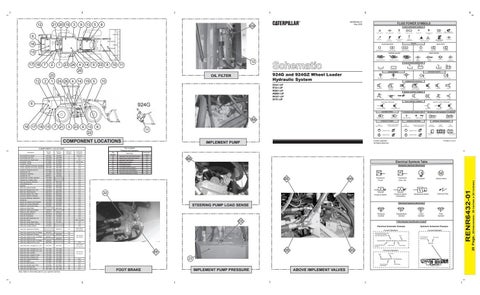
924G and 924GZ Wheel Loader Hydraulic System
OIL FILTER 24 26
1
4
19
14
5
10
RETURN ABOVE FLUID LEVEL
PRESSURIZED
PRESSURE
ROTATING SHAFTS
FLOW
TEMPERATURE
SOLENOID or MANUAL
SOLENOID
MANUAL SHUTOFF
PUSH-PULL LEVER
GENERAL MANUAL
23
9
13
SPRING LOADED
22
COMPONENT LOCATIONS
Accumulator Gp -Brake Accumulator Gp -Pilot Accumulator Gp -Ride Control Connector -Orifice Connector -Orifice Cooler -Hydraulic Oil Cooler, Standard Cooler -Hydraulic Oil Cooler, Heavt Dut Cooler As -Dual Disc Axle Oil Cylinder Gp -Lift Cylinder Gp -Steering Cylinder Gp -Tilt Cylinder Gp -Coupler, Standard Cylinder Gp -Coupler, Wide Filter Gp -Element 126-1818 Hand Metering Unit Manifold Motor Gp -Axle Oil Cooler Motor Gp -Radiator Hydr. Fan Motor Gp -Reversing Fan Pump Gp -Brake / Fan / Filter Pump Gp -Spplmnt. Steering Pump Gp -Steering / Implement Screen As Sensor Gp -Brake Pump Pressure Sensor Gp -Xmssm Neutralizer Switch As -Axle Cooler Press. Switch As -Float Press. Switch As -Ride Contr Disable Switch As -Sec. Steering Tank Gp-Hydraulic Oil Valve As -Foot Brake Valve Gp -Ball, Dead Eng. Lwr Valve Gp -Check Valve Gp -Check, Back Press. Valve Gp -Combination, Rlf/ Dvtr Valve Gp -Coupler Control
Part No. 924G
Part No. 924GZ
Machine Location
Schematic Location
140-9251 243-4398 223-9698 8C-0564 3E-2335 239-7394 239-7395 205-3652 141-7483 142-6251 268-9437 190-3085 188-0982 209-3149 214-4153 209-0789 205-5268 205-3669 205-3778 262-2875 205-5266 163-2428 247-8298 224-4536 290-5825 3E-7690
140-9251 243-4398 223-9698 8C-0564 3E-2335 239-7394 239-7395 205-3652 152-4187 142-6251 152-5306
1 2 3 4 5 6 6 7 8 9 10 11 11 12 13 14 15 16 16 17 18 19 21 17 22 15 23 23 14 20 22 5 13 14 14 14
B-9,C-9 A-7 D-7 A-4 to A-6 C-6 A-9 A-9 B-9 C-6 E-9 C-6 E-8 E-8 A-9 D-9 C-8 A-9 A-8 A-9 A-8 C-9 B-8 B-9 B-8 C-9 B-9 A-6 A-6 C-8 A-8 B-9 C-6 D-9, D-8, D-6 C-8 C-6 D-8
23
B-4 to B-6, D-1 to D-3
126-6916 230-5771 201-8108 144-8521 112-1817 9T-1013 212-7521 173-4032 233-2549
Valve Gp -Implement 2 Section
209-3149 214-4153 209-0789 205-5268 205-3669 205-3778 262-2875 205-5266 163-2428 247-8298 224-4536 290-5825 3E-7690 229-1537 230-5771 201-8108 144-8521 112-1817 9T-1013 212-7521
209-0273
Valve Gp -Implmnt 2 Sec. W/ Regen Valve Gp -Implement 3 Section Valve Gp -Implmnt 3 Sec. W/ Regen Valve Gp -Implmnt 4 Sec. Valve Gp -Implmnt 4 Sec. W/ Regen Valve Gp -Intgrtd 3rd Fnct. Cntrl
209-0270
Valve Gp -Pilot, 2 Single Func. Lvrs
212-1301
212-1301
4
Valve Gp -Pilot, 3 Single Func. Lvrs Valve Gp -Pilot, 4 Single Func. Lvrs Valve Gp -Pilot, Joystick Valve Gp -Pilot, Joystick / 2 Aux. Valve Gp -Pilot, Joystick / Aux. Valve Gp -Pressure Reducing Valve Gp -Relief Valve Gp -Ride Control Valve Gp -Shutoff, Hydr. Drain Valve Gp -Pilot Shut-Off Valve Gp -Sol, Ride Control
212-1304 212-1306 212-1302 212-1307 212-1305 185-5209 251-0907 141-1481 6V-7238 233-7133 297-1209
212-1304 212-1306 212-1302 212-1307 212-1305 185-5209 251-0907 141-1481 6V-7238 233-7133 297-1209
4 4 4 4 4 24 25 3 24 26 26
209-0274 209-0271 209-0275 209-0272 262-9706
Note: Refer to Parts Manuals for your specific machine.
23 23 23 23 23 23
HYDRAULIC AND PNEUMATIC CYLINDERS
LINES JOINING
SINGLE ACTING
HYDRAULIC MOTORS FIXED DISPLACEMENT
VARIABLE DISPLACEMENT NON-COMPENSATED
UNIDIRECTIONAL
UNIDIRECTIONAL
BIDIRECTIONAL
BIDIRECTIONAL
DOUBLE ACTING
INTERNAL PASSAGEWAYS
FLOW IN ONE DIRECTION
TWO POSITION
THREE POSITION
INFINITE POSITIONING
PARALLEL FLOW
CROSS FLOW
FLOW ALLOWED IN EITHER DIRECTION
Printed in U.S.A.
© 2008 Caterpillar All Rights Reserved
IMPLEMENT PUMP
Tap Number
Description
Schematic Location
AA
Implement Pump Load Sense Pressure
B-8
BB
Steering Pump Load Sense Pressure
B-8
CC
Implement Pump Pressure
C-6
DD
Steering Pump Pressure
B-7
EE
Pilot Supply Pressure
A-7
FF
Front Brake Pressure
B-9
GG
Tilt Cylinder Rod End Pressure
C-6
Tilt Cylinder Rod Head Pressure
C-6
HH II
Rear Axle Cooler Circuit Pressure
B-9
SOS
Hydraulic Oil Sampling Port (SOS)
A-9
BB Electrical Symbols Table Hydraulic Symbols (Electrical)
G
EE
HH
22
Transducer (Fluid)
Transducer (Gas / Air)
Pressure Switch (Adjustable)
Pressure Switch
M
Generator
Electric Motor
Electrical Wire
Temperature Switch
Electrical Symbols (Electrical)
STEERING PUMP LOAD SENSE
T
Pressure Symbol
Temperature Symbol
CC
Level Symbol
Flow Symbol
Wire Number Identification Codes
Electrical Schematic Example
Hydraulic Schematic Example Current Standard
Current Standard Harness identification code This example indicates wire 135 in harness "AG".
B-4 to B-6, D-1 to D-3
Wire Circuit Number Identification
Wire Color
325-AG135 PK-14 E-2
325-PK
A-4 to A-6, C-1 to C-3
Circuit Identification Number
DD
FF
A-4 to A-6, C-1 to C-3
B-7 C-9 D-7 B-7 A-7 D-7
INTERNAL SUPPLY PRESSURE
COMPLETE
Tap Locations Pressure and Sampling
COMPONENT LOCATIONS Description
LINES CROSSING
GAS CHARGED
SPRING
REMOTE SUPPLY PRESSURE
CROSSING AND JOINING LINES
VARIABLE DISPLACEMENT NON-COMPENSATED
PEDAL
SIMPLIFIED
HYDRAULIC PUMPS
11
PUSH BUTTON
INTERNAL RETURN
FIXED DISPLACEMENT
8
DETENT
THERMAL
PILOT CONTROL SYMBOLS
RELEASED PRESSURE
AA
3
SERVO
SOLENOID and PILOT or MANUAL
SOLENOID and PILOT
ACCUMULATORS
21
BIDIRECTIONAL
MANUAL CONTROL SYMBOLS
EXTERNAL RETURN
7
UNIDIRECTIONAL
COMBINATION CONTROLS
924G
16 17 18 15
PILOT CONTROLLED
RETURN BELOW FLUID LEVEL
MEASUREMENT
DDA1-UP RTA1-UP RBB1-UP WMB1-UP WGX1-UP DFZ1-UP
6
SHUTTLE
SPRING LOADED
BASIC SYMBOL
FLUID STORAGE RESERVOIRS
10 11
26 12
INFINITE POSITION
GG
Wire Color
Previous Standard Wire Color
Wire
23
Wire Gauge
325-PK-14 B Circuit Number Identification
FOOT BRAKE
IMPLEMENT PUMP PRESSURE
ABOVE IMPLEMENT VALVES
A
Wire Gauge (EXAMPLE VALVE)
(Dimensions: 39 inches x 24 inches)
2
P T SHIFTED POSITION
P T NORMAL POSITION
20 Page,
7
CHECK VALVES
AB
RENR6432-01
17 18
FOUR-WAY
THREE-WAY
CONTROL VALVES AB
12
ATTACHMENT
LINE RESTRICTION VARIABLE and PRESSURE COMPENSATED
VALVES
VALVE ENVELOPES
ONE POSITION
HYDRAULIC PNEUMATIC ENERGY TRIANGLES