Wire Description Wire Color
101
RD
102
Component Location
Wire Number
Wire Color
BAT (+)
751
GN
XMSN SHIFT SOL NO. 1
RD
HD LMP
752
YL
XMSN SHIFT SOL NO. 2
105
RD
KEY SW
754
BU
XMSN SHIFT SOL NO. 3
106
WH
FLOOD LAMP RELAY
755
OR
XMSN SHIFT SOL NO. 4
106
RD
MAIN BREAKER
761
GY
LIFT KICKOUT
108
BU
SEAT HEATER
762
YL
BUCKET POSITIONER
109
RD
ALT OUTPUT (+) TERM.
A700
OR
DIGITAL SENSOR POWER(+8V)
Description
Control Circuits (cont’d)
Power Circuits
112
PU
MAIN POWER RLY OUTPUT
A701
GY
INJECTOR #1
113
OR
OPR MON PANEL B+ SWITCHED
A702
PU
INJECTOR #2
114
GN
WARNING HORN (FORWARD)
A703
BR
INJECTOR #3
118
GY
F & R WIPERS
A704
GN
INJECTOR #4
119
PK
L & R WIPERS
A705
BU
INJECTOR #5
120
YL
VOLTAGE CONV / FLOOD LAMP SW / RADIO
A706
GY
124
GN
BLOWER SW
A707
129
BU
CIGAR LIGHTER
135
BU
RADIO / POWERPORT
146
GY
150 164 188
WH
Actuator - Water Valve
F-8
Machine Location 1
D-13
Machine Location 28
Alarm - Action
H-2
A
Sensor - Transmission Oil Temp
E-13
28
Alarm - Backup
D-17
2
Sensor - Transmission Speed
G-14
28
Alternator
D-14
3
Sensor - Turbo Outlet Pressure
I-17
20
F-14,F-1
3
Sensor - Ultrasonic Fuel Level
H-13
29
Batteries - 12V
I-17
4
Solenoid - A / C Clutch
E-14
3
Batteries - 12V (Attch)
B-16
5
Solenoid - Bucket Positioner Detent
G-6
B
Breakers - Alt, Eng Con, Key, Main, Lamps
B-8
D
Solenoid - Dual Tilt (Attch)
F-1
45
Off Machine Switch Specification
Description
Part No. 171-8708
114-5333
3E-6450
174-4312
131-4135
Function Coolant Flow
Actuate
Deactuate
Contact Position
362 ± 29 mN (45.6 mm ID Point)
303 mN MIN
Normally Open
(1.3 ± .1 oz, 1.8 in ID point)
(1.1 oz MIN)
275 to 1750 kPa ¹
-
A/C High/Low Pressure
Normally Open ²
(40 to 255 psi )
-
1200 kPa MAX
700 ± 100 kPa
A-C, Normally Closed
(175 psi MAX)
(100 ± 15 psi)
A-B, Normally Open
Park Brake Pressure
8270 kPa MAX
6890 ± 345 kPa
A-B, Normally Open
Brake Oil Pressure
(1200 psi MAX)
(1000 ± 50 psi)
A-C, Normally Closed
Steering Oil Temp
102 ± 3ºC
90ºC
Normally Closed
(216 ± 38ºF)
(194ºF)
Primary Steering Pressure
Schematic Location
Component
Arc Suppressor
Schematic Location
Component Sensor - Torque Converter Output Speed
Bus Bar
D-16
6
Solenoid - Impeller Clutch Proportional
D-13
28
Clusters - Gauge/Speedometer/Tachometer
G-2
A
Solenoid - Injector 1 & 3
F-18
21
Control - Engine ECM
A-17
7
Solenoid - Injector 2 & 4
E-18
7
¹ A hysteresis band exists: with increasing pressure the closed condition can be maintained up to 2800 kpa (405 psi), with decreasing pressure the closed condition can be maintained down to 170 kpa (25psi).
Control - STIC
F-5
C
Solenoid - Injector 5 & 7
F-18
30
² Contact postion at the contacts of the harness connector.
Control - Power Train
A-5
E
Solenoid - Injector 6 & 8
E-18
31
INJECTOR #6
Control Board
F-9
1
Solenoid - Injector 9 & 11
F-17
32
PU
INJECTOR #7
Control Group - Dimmer
F-3
A
Solenoid - Injector 10 & 12
E-17
33
A708
BR
INJECTOR #8
Fuses
B-4, B-6
E
Solenoid - Lift Kickout Detent
G-6
B
A709
OR
INJECTOR #9
Ground - Electronics Bay to Stud #3
C-3
E
Solenoid - Lockup Clutch Proportional
D-13
28
IMPLEMENT CONTROL
A710
GY
INJECTOR #10
Ground - Engine
A-16
7
Solenoid - Lower Kickout Detent
G-5
B
RD
BAT (+) ADEM ECM BKR
A711
PU
INJECTOR #11
Ground - Engine End Frame To Platform
F-7
9
Solenoid - Ride Control (Attch)
C-1
24
WH
POWERTRAIN CTRL
A712
BR
INJECTOR #12
Ground - Frame
H-12
10
Solenoid - Start Aid
D-13
D
KEYPAD
A746
PK
TURBO OUTLET PRESSURE
Ground - Platform
E-10
9
Solenoids - Transmission
C-12
34
A747
GY
ATMOSPHERIC PRESSURE
Ground Stud #1
A-14
E
Switch - A / C High / Low Pressure
F-14
3
Ground Circuits
Resistor and Solenoid Specifications Part No.
Component Description
Resistance (Ohms)¹
200
BK
MAIN CHASSIS
A751
YL
FUEL TEMPERATURE
201
BK
OPR MON PANEL CMS
D728
BU
STIC GROUP FORWARD (G750)
9X-4383
Resistor -
Blower Motor Speed
202
BK
XMSN CTRL
D729
GY
STIC GROUP REVERSE (G755)
3E-7842
Resistor -
203
BK
CHASSIS DIAGNOSTIC
D730
GN
STIC GROUP UPSHIFT (NC) (G768)
105-1500
207
BK
STARTER DIAGNOSTIC
D731
WH
STIC GROUP UPSHIFT (NO) (G760)
102-0347
229
BK
BAT (-) - ENGINE
D732
YL
STIC GROUP DOWNSHIFT (NC) (G761)
3E-6333
Solenoid -
Start Aid
250
BK
PAYLOAD MON - CUSTOMER
D733
BR
STIC GROUP DOWNSHIFT (NO) (G762)
186-4126
Solenoid -
Impeller Clutch Proportional
7.75 ± 1.0
251
BK
PAYLOAD MON - SYSTEM
D734
PU
STIC GROUP NEUTRAL (G763)
170-0761
Solenoid -
Lockup Clutch Proportional
8.7
290
BK
CMS SERVICE
E701
PK
AUTO RIDE CNTL SW
3E-9205
Solenoid -
Dual Tilt
24.9 ± 0.4
Motor - LH Wiper
F-3
291
BK
CMS CLEAR
E705
BU
IMPELLER CLUTCH PRESSURE SIGNAL
152-8340
Solenoid -
Ride Ctrl
32.6 ± 1.6
Motor - Rear Wiper
I-12
H-16
E
Switch - Blower
I-6
B
overall 3.0 ± 0.15 ; tap 1.0 ± .05
Horn - Forward (990)
B-1, I-1
11
Switch - Bucket Positioner
G-1
44
Starter / Diagnostic Conn
150 ± 7.5
Horn - Forward (844)
E-1,F-1
11
Switch - Coolant Flow
I-16
36
Solenoid -
Injector (12)
1.55 ± 0.2
Lamp - Action
H-2, G-2
A
Switch - Disconnect
I-16
37
Solenoid -
A/C Clutch
14.4 ± 0.6
Lighter - Cigar
I-8
B
Switch - Dual Tilt
G-5
A
Monitor - Comp Mon Sys (CMS)
I-2
A
Switch - Dual Wiper
G-7
B
Motor - Blower
F-9
1
Switch - Flood Lamp
I-7
B
Motor - Front Wiper
F-3
12
Switch - Front Intermittent Wiper
I-8
B
13
Switch - Ground Level Shutdown
I-14
3
14
Switch - Horn
G-4
C
Ground Stud #4
6
299
BK
WTL IMPL CTRL
E707
GN
VMIS DISPLAY +V
Motor - RH Wiper
E-2
15
Switch - Key Start
H-9
B
A234
BK
J1939 SHIELD
E708
PK
MODULE +V
Motor - Starter
E-13
16
Switch - Kickout Set
I-10
A
A251
BK
FRONT AXLE OIL TEMP SENSOR
E735
PU
MODE SELECT SW
Motor - Starter (Attch)
G-13
17
Switch - Lift Kickout
H-1
38
A273
BK
XMSN CTRL
E779
BR
RELAY PANEL
Motor - Washer
E-12
1
Switch - Load and Carry
I-10
A
E793
BU
ATA DATA LINK (-)
Receptacle - Aux Start
H-17
18
Switch - Opr. Monitor Mode Select
H-9
A
E794
YL
ATA DATA LINK (+)
Relay - Flood Lamp
C-5
E
Switch - Park Brake
H-14
39
Basic Machine Circuits 301
BU
STARTER NO. 1 SOL
¹ At room temperature unless otherwise noted.
302
OR
STARTER NO. 1 RESISTOR TO DIAGNOSTIC
E795
YL
ENG OIL TEMP SENSOR
Relay - Horn
G-4
C
Switch - Park Brake Oil Pressure
304
WH
STARTER RLY NO. 1 OUTPUT
E796
GN
RAIL PRESS SENSOR
Relays - Main and Start
B-8
D
Switch - Park Brake Pressure
306
GN
STARTER RELAY COIL
E797
WH
RAIL PRESS CONTROL RETURN
Relay - Start Aid
C-8
D
Switch - Payload Store
Related Electrical Service Manuals
307
OR
KEY SW TO NEUT START SW
E798
PK
RAIL PRESS CONTROL VALVE
308
YL
MAIN POWER RLY COIL
E799
BR
PWM #1 AND #2 RETURN
310
PU
START AID SW TO START AID SOL
F700
BU
ENGINE ECM SPARE
Alternator:
312
BU
STARTER NO. 2 SOL TO RESISTOR
F701
BR
ENGINE ECM SPARE
Starting Motor:
313
GY
STARTER NO. 2 RESISTOR TO DIAGNOSTIC
F702
GN
THROTTLE
314
PU
STARTER RLY NO.2 OUTPUT
F703
GY
ENGINE ECM UNUSED
320
OR
HORN RLY COIL TO SW
F704
OR
ENGINE ECM SPARE
321
BR
BCKP ALARM
F705
PK
ENGINE ECM UNUSED
322
GY
WARNING HORN (FORWARD)
F706
PU
ENGINE ECM SPARE
Sensor - Engine Oil Pressure
H-17
21
Switch - Running Lamp
338
PK
FLOOD LAMP RLY COIL
F707
WH
ENGINE ECM SPARE
Sensor - Engine Oil Temperature
H-17
21
Switch - Stairway Access Lamp
Monitoring Circuits
F708
YL
ENGINE ECM SPARE
Sensor - Engine Speed
F-13
28
Switch - Start Aid
Title
Resistor - Blower
Form Number
C-2
39
G-14
39
F-4
A
F-9
1
Switch - Primary Steering Pressure
G-14
39
Resistor - Starter Diagnostic
E-14
16
Switch - Quickshift
H-8
B
G-13
17
Switch - Rear Wiper
I-7
B
C-8
D
Switch - Reduced / Max Rimpull
G-5
C
200-8277
SENR7508
Resistor - Starter Diagnostic (Attch)
6V-0890
SENR3860
Resistor - System Voltage (CMS)
CAT Mon. System(CMS):
154-7443
SENR1394
Selector - Water Valve Temp
I-11
B
Switch - RH Dash Lamp
F-4
B
Eng. Troubleshooting / ECM:
105-6122
RENR2373
Sensor - Atmospheric Pressure
I-17
20
Switch - RH Service Brake
B-2
19
Powertrain ECM:
172-9389
RENR6252
Sensor - Backup Cam S / T
I-17
21
Switch - Ride Control
G-9
B
Payload ECM:
112-1572
SENR6614
Sensor - Coolant Temp
I-17
21
Switch - Rimpull Rotary
I-5
B
403
GN
ALTERNATOR (R) TERM.
F709
BU
ENGINE ECM SPARE
Sensor - Front Axle Oil Temp
F-1,E-1
22
Switch - Steering Lock
410
WH
OPR MON ACTION ALARM
F710
BR
START AID RELAY
Sensor - Fuel Temperature
H-17
21
Switch - Steering Oil Temp
H-7
B
H-7,I-14
B,37
H-9
B
F-5
C
H-14
40 19
411
PK
OPR MON MASTER ACTION LAMP
F711
GN
RS232 DATALINK TX
Sensor - Impeller Clutch Pressure
E-13
28
Switch - Stoplamp
A-2
412
BU
OPR MON COOL FLOW/DS2
F712
GY
RS232 DATALINK RX
Sensor - Implement Oil Temp
A-3
23
Switch - Thermostat
F-9
1
417
GY
PRIMARY STER SW
F713
OR
ENGINE ECM SPARE
Sensor - Inlet Air Temp
H-17
20
Switch - Throttle Lock
I-6
B
419
YL
OPR MON PARKING BRAKE
F714
PK
ENGINE ECM SPARE
426
BR
OPR MON POWER TRAIN OIL FILTER
F715
PU
SHUTDOWN (NO)
429
YL
OPR MON BRAKE OIL TEMP
F716
WH
SHUTDOWN (NC)
432
PK
OPR MON BRAKE PRESS. (OIL)
F717
YL
THROTTLE LOCK SET / DECEL SW
442
GY
HYD SYSTEM TEMP GAGE
F718
BU
THROTTLE LOCK RESUME / ACCEL SW
CONN 1
E-18
7
CONN 2
E-18
31
CONN 3
E-17
33
CONN 4
F-18
21
CONN 5
F-18
30
443
YL
POWER TRAIN TEMP GAGE
F719
BR
THROTTLE LOCK SW
446
PU
BRAKE OIL TEMP GAGE
F720
GN
START AID SW
447
PK
FUEL LEVEL GAGE
F721
GY
RH SERV BRAKE SW (NC)
Connector Location Connector Number
Schematic Location
Machine Location
452
PU
TORQUE CONVERTER
F722
OR
RH SERV BRAKE SW (NO)
CONN 6
F-17
32
A401
RD
ELECTRICAL SYSTEM NO.1 VOLTAGE
F723
PK
SPARE / TDC PROBE (+)
CONN 7
G-18, H-4
46
A451
WH
OPR MON STEERING OIL TEMP
F724
PU
C413
YL
CMS CONT DATA
F725
WH
SPARE / TDC PROBE (-)
CONN 8 Customer Data Conn
G-18
8
ENGINE ECM SPARE
CONN 9
I-18
21
C414
BU
CMS CONT LOAD
F726
YL
INJECTOR COMMON 1 & 3
CONN 10
C-17
51
C415
WH
VMIS DISPLAY KEYDATA
F727
BU
INJECTOR COMMON 2 & 4
CONN 11 Timing Cal Conn
B-16
7
CONN 12
H-15
50
CONN 13
G-15
50
CONN 14
C-15
3 D
C491
PU
PARK BRAKE PRESSURE
F728
BR
INJECTOR COMMON 5 & 7
F417
YL
PAYLOAD STORE
F729
GN
INJECTOR COMMON 6 & 8
F730
GY
INJECTOR COMMON 9 & 11
CONN 15
A-14
Accessory Circuits
Sensor - LH Brake Pedal Position
A-2
19
Switch - Throttle Lock Resume / Accel
G-6
C
Sensor - Lift Cylinder Pressure (Attch)
G-1
24
Switch - Throttle Lock Set / Decel
G-6
C
Sensor - Lift Position (Attch)
G-1
25
Switch - Torque Converter Lockup
H-8
B
Sensor - Primary Cam S / T
I-17
21
Switch - Transmission Oil Filter Bypass
A-3
41
Sensor - Rail Pressure
I-17
26
Valve - Rail Pressure Control
I-17
21
Sensor - Rear Axle Temp
G-13
27
Voltage Converter
H-4
8
Sensor - Throttle
G-3
19
T
Pressure Symbol
Normally closed switch that will open with an increase of a specific condition. No circle indicates that the wire cannot be disconnected from the component. This indicates that the component has a wire connected to it that is connected to ground.
This indicates that the component does not have a wire connected to ground. It is grounded by being fastened to the machine. Reed Switch - A switch whose contacts are controlled by a magnet. A magnet closes the contacts of a normally open reed switch; it opens the contacts of a normally closed reed switch.
990 Series II Wheel Loader and 844 Wheel Tractor Electrical System 990 II: BCR1-UP
Single Wire Connector
1 2
Component Identifiers (CID¹) Module Identifier (MID²) Caterpillar Monitoring System (MID No. 030)
50
H-14
50
502
OR
WIPER — FRONT (HI)
F741
WH
RIMPULL SW
CONN 18
I-13
49
CID
503
BR
WIPER - REAR (PARK)
F778
OR
IMPLEMENT CTRL TILT K.O. SET SW (NO)
CONN 19
I-13
D
0096
Fuel Level Sender
0168
Electrical System Voltage
504
YL
WIPER - REAR (LO)
F779
WH
IMPLEMENT CTRL TILT K.O. SET SW (NC)
CONN 20
I-13
48
0100
Engine Oil Pressure Sensor
0254
Payload Electronic Control Module
505
BU
WIPER - REAR (HI)
G747
OR
XMSN CONT LUC PROP SOL
CONN 21
H-13
49
0110
Engine Coolant Temperature Sensor
0350
Lift Linkage Position Sensor
CONN 22
G-13
17
506
PU
WASHER - FRONT
G748
PU
XMSN CONT STEER CONSOL SW 1
0177
Transmission Oil Temperature Sensor
0364
Head End Lift Cylinder Pressure Sensor
CONN 23
G-13
17
0248
Data Link
0769
Rod End Lift Cylinder Pressure Sensor
Component
CID
G749
YL
XMSN CONT STEER CONSOL SW 2
CONN 24
D-12
D
RADIO SPEAKER - RIGHT
G750
BU
XSMSN CONT FWD SW TO GND
0263
Sensor Power Supply
0817
Internal Backup Battery
CONN 25
E-12
I
RADIO SPEAKER - RIGHT (COMMON)
G755
GY
XMSN CONT REV SW TO GND
0271
Action Alarm
0820
Keypad Data Link
CONN 26
E-12
49
0324
Action Lamp
CONN 27
F-12
49
0427
Front Axle Oil Temperature Sensor
0428
Rear Axle Oil Temperature Sensor
CID
0600
Hydraulic Oil Temperature Sensor
0041
Sensor Power Supply Voltage
0819
Display Data Link
0070
Parking Brake Switch Fault
0821
Display Power Supply
0168
Electrical System Voltage
0826
Torque Converter Oil Temperature Sensor
0444
Magnetic Switch (Start Relay)
0830
Brake Oil Temperature Sensor
0590
Electronic Control Module (Engine)
PK BRK PRESS SW (NO) QUICKSHIFT SW (N.C.)
CONN 28
F-12
49
513
OR
A/C COMPR/REFRIGERANT PRESS. SW
G759
WH
QUICKSHIFT SW (N.O.)
CONN 29
C-11
34
515
GY
BLOWER MOTOR (HI)
G760
WH
XMSN CONT UPSHIFT SW (NO)
CONN 30
A-10
49
516
GN
BLOWER MOTOR (MEDIUM)
G761
YL
XMSN CONT DOWNSHIFT SW (NC)
CONN 31
A-10
48
517
BU
BLOWER MOTOR (LO)
G762
BR
XMSN CONT DOWNSHIFT SW (NO)
521
YL
A/C SW TO REFRIGERANT SW
G763
PU
XMSN CONT NEUT SW
522
WH
A/C CLUTCH TO THERMOSTAT SW
G764
PK
XMSN CONT PK BRK LVR SW
523
BR
WIPER - LEFT (PARK)
G765
GN
XMSN CONT TC LOCKUP SW
CONN 36
B-9
D
524
BU
WIPER - LEFT (LO)
G766
GN
XMSN CONT RIDE CONT SW 1
CONN 37 Service Tool Conn
A-8
D
525
GY
WIPER - LEFT (HI)
G767
WH
XMSN CONT RIDE CONT SW 2
CONN 38 Diagnostic Conn
A-8
D
526
YL
WIPER - RIGHT (PARK)
G768
GN
XMSN CONT UPSHIFT SW (NC)
CONN 39
E-8
9
527
GN
WIPER - RIGHT (LO)
G794
OR
XMSN QUICKSHIFT INDICATOR LAMP
CONN 40
F-8
528
PK
WIPER - RIGHT (HI)
H712
WH
LOAD AND CARRY SW
CONN 41
F-8
529
WH
WASHER - DUAL
H721
OR
LOAD AND CARRY SW
CONN 32
F-10
I
CONN 33
H-10
I
CONN 34 CONN 35
F-9 E-9
29
37 4
49
18
7
36 2
31
26
20 6
3
9
48
42
14
49 48
10
B
9
12
22
24
34
32
30
A
47
1
13 19
39
8
28
17
25
50
C
27
21
D
40
33
16
51
I
11
46
45
43
44
44
15
Engine Control System (MID No. 036)
38
35 CID
Component
0650
Harness Code
E100
Low Engine Oil Pressure Warning
0678
Modulating Valve (Torque Converter Impeller Clutch)
E164
High Injector Actuation Pressure
0002
Cylinder 2 Injector Solenoid
0679
Modulating Valve (Torque Converter Lockup Clutch)
E190
Engine Overspeed Warning
9
0003
Cylinder 3 Injector Solenoid
1401
Modulating Valve (No. 1) (Transmission)
47
0004
Cylinder 4 Injector Solenoid
1402
Modulating Valve (No. 2) (Transmission)
Cylinder 5 Injector Solenoid
1403
Modulating Valve (No. 3) (Transmission)
1404
Modulating Valve (No. 4) (Transmission)
1405
Modulating Valve (No. 5) (Transmission)
E
5
41
11
CONN 42
F-8
47
0005
CONN 43
F-8
46
0006
Cylinder 6 Injector Solenoid
XMSN CONT L. BRAKE PEDAL POS SENS
CONN 44
E-7
46
0007
Cylinder 7 Injector Solenoid
XMSN CONT IMPELLER CLUTCH PROP SOL
CONN 45
B-7
D
0008
Cylinder 8 Injector Solenoid
¹ The CID is a diagnostic code that indicates which component is faulty. ² The MID is a diagnostic code that indicates which electronic control module diagnosed the fault.
A513
PK
VOLTAGE CONV MEMORY OUTPUT
818
BR
PAYLOAD CONT SERIAL DATA (TRANSMIT)
CONN 46
C-6
E
0009
Cylinder 9 Injector Solenoid
A523
PU
WATER VALVE TEMP POT POS 1
819
GY
PAYLOAD CONT SERIAL DATA (RECEIVE)
CONN 47
E-6
46
0010
Cylinder 10 Injector Solenoid
A524
BR
WATER VALVE TEMP POT POS 2
892
BR
PAYLOAD CONT CAT DATA LINK (-)
CONN 48
F-6
C
0011
Cylinder 11 Injector Solenoid
A525
GN
WATER VALVE TEMP POT POS 3
893
GN
PAYLOAD CONT CAT DATA LINK (+)
CONN 49
F-6
35
0012
Cylinder 12 Injector Solenoid
CONN 50
F-6
C
0042
Injection Actuation Valve
CONN 51
H-6
B
0091
Throttle Position
CONN 52
H-6
B
0100
Engine Oil Pressure
0110
Coolant Temperature
0164
Injection Actuation Pressure
PK
WATER VALVE ACTUATOR
8124
GN
SEAT HEATER AND SW
A527
BU
WATER VALVE ACTUATOR
900
PU
XMSN SHIFT SOL NO. 5
A528
YL
WATER VALVE ACTUATOR
975
WH
CST AUTOSHIFT- SOL RETURN
CONN 53
I-5
8
A529
WH
WATER VALVE ACTUATOR
976
OR
XMSN CONT RIDE CONTROL SOL
CONN 54
G-5
C
A530
OR
WATER VALVE ACTUATOR
990
OR
ANALOG SENSOR POWER (+ 5V)
CONN 55
E-5
46
0168
System Voltage
C529
GY
LIFT PRESS SENSOR
993
BR
ANALOG SENSOR COMMON
CONN 56
C-4
E
0172
Intake Manifold Air Temp
BU
LIFT POSITION SENSOR
994
GY
OIL PRESSURE (FILTERED)
CONN 57
E-4
46
4
C530
0174
Fuel Temperature
995
BU
COOLANT TEMPERATURE
CONN 58
E-3
14
5
0175
Oil Temperature
CONN 59
E-3,F-2
24
0190
CONN 60
E-3
9
CONN 61
D-3
24
CONN 62
A-2
19
OR
ANALOG SENSOR POWER (+ 5V)
607
PK
FLOOD LAMP - FRONT
998
BR
DIGITAL SENSOR RETURN
608
GN
FLOOD LAMP - REAR
999
WH
PRIMARY CAMSHFT SPEED/TIMING
CONN 63
A-2
19
610
OR
HEAD LAMP BASIC
C967
BU
INLET AIR TEMP
CONN 64
B-2
42
615
YL
CAB FLOOD LAMP/ROPS
C985
BU
XMSN CONT +8V SENSOR SUPPLY
CONN 65 (990)
C-2
43
CONN 66 (990)
H-2
44
622
PU
STAIRWAY ACCESS LAMP
E955
OR
WLPMS PH II KEYPAD DATA
623
BU
STAIRWAY ACCESS LAMP
E972
BU
SPI DATA LINK END
625
PK
RH DASH "COURTESY" LAMP
E987
WH
XMSN OUTPUT SPEED RETURN
637
GN
TC LOCKUP LED
E988
PU
RIMPULL ROTARY SW
CONN 67
I-2
42
CONN 68 (990)
G-1
43
CONN 69 (844)
F-1
42
CONN 70 (844)
F-1
42
641
OR
LADDER LAMP
E989
WH
RIMPULL ROTARY SW
CONN 71 (844)
F-1
44
661
GN
TACHOMETER LAMP
G939
PK
TC OUTPUT SPEED RETURN
CONN 72 (844)
E-1
42
662
YL
SPEEDOMETER LAMP
K933
BU
FRONT AXLE OIL TEMP SENSOR
CONN 73 (844)
E-1
42
663
GY
GAUGE LAMP
K983
BU
OIL TEMP SENSOR SUPPLY
CONN 74
E-1
44
679
GY
RIMPULL INDICATOR LAMP
L912
WH
XMSN CONT ENG SPEED
Control Circuits
L913
OR
XMSN CONT ENG SPEED RETURN
709
OR
SENSOR POWER SUPPLY
P911
PU
RIMPULL ROTARY SW
710
GN
XMSN SPEED PICKUP SIGNAL
P912
BU
RIMPULL ROTARY SW
CONN 75 CMS Serv Mode Plug I-3 A The connectors shown in this chart are for harness to harness connectors. Connectors that join a harness to a component are generally located at or near the component. See the Component Location Chart.
13 15
8
C
14 51 7 20
26 21 30
3
36
D
18
31
49
E
32
9
17
28
16 48
5
37
12
35 47
19
41 50
6 4
46
1
23
10
2
33
A
B
27
34
42 43
39
11
38 25
44
44
24 45
40
29
22
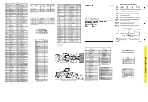
Machine Harness Connector And Component Locations
Power Train ECM EID
Description
E049
Coasting in Neutral Warning
Failure Mode Identifiers (FMI)¹
A526
997
Condition
Cylinder 1 Injector Solenoid
YL
STOP LAMP
Engine ECM Event Code
0001
42
23
GN
OR
Event Codes
High Engine Coolant Temperature Warning
H724
604
81
E017
H722
ENGINE SPEED/TIMING SENSOR POWER
80
844
Limit Switch (Steering/Transmission Lock)
DUAL TILT SOL. S2
GN
Code
990 II
Rocker Switch (Transmission Direction)
DUAL TILT SOL. S1
996
Machine Codes Machine
0626
YL
DASH LAMP BASIC
Printed in U.S.A.
0623
PK
BR
Typical representation of a Sure-Seal connector. The plug and receptacle contain both pins and sockets.
Component
554
600
1 2
Power Control System (MID No. 081)
553
Lighting Circuits
Typical representation of a Deutsch connector. The plug contains all sockets and the receptacle contains all pins.
Component
WASHER - REAR
YL
200-BK-14
Component Identifiers (CID¹) Module Identifier (MID²) (cont’d) Payload Control System (MID No. 074)
G-14
PU
2
E = Located around hydraulic oil tank.
CONN 17
G758
Plug
D = Located around relay panel.
CONN 16
G756
Receptacle
Wire Gauge
C = Located inside of left console.
BACKUP CAMSHAFT SPD/TMG
RADIO SPEAKER - LEFT (COMMON)
1
A = Located inside of cab. B = Located inside of right console.
INJECTOR COMMON 10 & 12
RADIO SPEAKER - LEFT
105-9344
Machine locations are repeated for components located close together.
PK
BR
AA
© 2002 Caterpillar All Rights Reserved
OR
GN
Circuit Number Identification
Fuse
Pin or Socket Number
F732
512
Wire Color
Ground Connection
F731
511
Socket
Component Part Number
Wire, Cable, or Harness Assembly Identification
325-PK-14
WIPER - FRONT (LO)
WH
Solenoid - A solenoid is an electrical component that is activated by electricity. It has a coil that makes an electromagnet when current flows through it. The electromagnet can open or close a valve or move a piece of metal that can do work.
A
WIPER - FRONT (PARK)
509
Relay (Magnetic Switch) - A relay is an electrical component that is activated by electricity. It has a coil that makes an electromagnet when current flows through it. The electromagnet can open or close the switch part of the relay.
Pin
BR
PU
T
Harness And Wire Symbols
GN
508
Sender- A component that is used with a temperature or pressure gauge. The sender measures the temperature or pressure. Its resistance changes to give an indication to the gauge of the temperature or pressure.
844: BBN1-UP
501
WH
Circuit Breaker Symbol
Flow Symbol
Level Symbol
Temperature Symbol
Normally open switch that will close with an increase of a specific condition (temp-press-etc.). The circle indicates that the component has screw terminals and a wire can be disconnected from it.
500
507
Electrical Schematic Symbols And Definitions
RENR6263 February 2002
FMI No.
Failure Description
0
Data valid but above normal operational range.
1
Data valid but below normal operational range.
2
Data valid but below normal operational range.
3
Data valid but below normal operational range.
Monitoring System Service Modes Service Mode
Number
Operator Mode Sequence
0
Voltage below normal or shorted low.
Harness Code
1
Current below normal or open circuit.
Numeric Readout
2
6
Current above normal or grounded circuit.
Service
3
Engine Speed
7
Current above normal or grounded circuit.
Digital Tattletale
4
0253
Personality Module
8
Abnormal frequency, pulse width, or period.
0254
Internal ECM
Units
5
9
Abnormal update.
0261
Timing
10
Abnormal update.
Cal 3
6
0262
Volt Sensor
11
Failure mode not identifiable.
Cal 2
7
Monitoring System Operator Modes
0263
Digital Sensor
12
Bad device or component.
0267
Engine Shutdown
13
Out of calibration.
0268
Programmable Parameters
14
N/A
Service Meter
0
0273
Turbocharger Outlet Pressure
15
N/A
Odometer - Machine Travel Distance
1
0274
Atmospheric Pressure
16
Out of calibration.
0296
XMSN ECM
Tachometer
2
17
Out of calibration.
0298
Service Brake
18
Sensor supply fault.
Scrolling (Diagnostic)
3
0342
Secondary Engine Speed
19
Condition not met.
0545
Start Aid Relay
0562
CMS
0650
Harness Code
0799
Service Tool
20 N/A ¹The FMI is a diagnostic code that indicates what type of failure has occurred.
Operator Mode
Number
RENR6263-00
Wire Number