Part No.
16 3 10
8
23
14
29
13
24
2
1
11 15
18 31
2
4
27 17 34
7
6
19
26
11 12
12
A
7
33
37
D
30
21
5
36
10
B
8
5
22
9
1
3
35 38
Actuate
Deactuate
Contact Position
Stoplamp Pressure
45 kPa MAX (6.5 psi MAX)
5 kPa MIN (0.5 psi MIN)
N.O.
7T0988
Engine Oil Pressure (CMS)
62 ± 21 kPa (9.0 ± 3.0 psi)
38 ± 21 kPa (5.0 ± 3.0 psi)
N.O.
8N1693
Engine Coolant Temperature (Ether Aid)
37.8 ± 2.8°C (100 ± 5°F)
26.7°C MIN (80°F MIN)
N.C.
8N2248
Hydraulic Oil Temperature (CMS)
101.7 ± 2.8°C (215 ± 5°F)
93.3°C MIN (200°F MIN)
N.C.
8T9792
Secondary Brake Air Pressure
9X1159
Steering (Primary-Secondary) Flow (CMS)
517 ± 35kPa (75 ± 5 psi)
Parking Brake Pressure (CMS)
448 ± 35kPa (65 ± 5 psi)
SENR4759 June 1990
*
4 grams (.14 oz.)
1.5 grams (.05 oz)
N.O.
517 ± 35kPa (75.0 ± 5.0 psi)
448 ± 35kPa (65.0 ± 5.0 psi)
N.O.
* = Pins 1-2 N.O.; Pins 1-3 N.C. N.O. = NORMALLY OPEN
9
6 32 20
Off Machine Switch Specification
2M9346
9X3210
25
C
E
4
28
Function
N.C. = NORMALLY CLOSED
Connector Location Connector
Machine Location
Harness And/Or Components
B-8
11
*
B - 8R9204 Computerized Monitoring System
E-4
20 Contacts
2
A-8R8159 Diagnostic Connector
B-12
12 Contacts
1
A-8R8159 B - 8R920
3
18 31
30
2
24
23
1
10 3
D
26
6
12
19 21
29 14
1
11 9 13
3
7 E
7
4
35 36 38
10 Contacts
33 6 12
9 27
5
17 34 8
28
37 10 25
15
8
4
16
B
C
32 20
Machine Location
A-8R8159 B-8R9204
A
11
Connector
1
9 Contacts
Schematic Location E-10
*
A-8R8159 Engine Shutdown Control
C-10
5
B-8R9204 L - 8R7067
A-3
B-8
5
B-8R9204 L - 8R7067
C-3
A-8R8159 E-8R8165
A-6
12
F-8R8164 Z-8R8169
D-2
4
A - 8R8159 F-8R8164
F-6
5
B-8R9204 JJ - 8R7202
D-5
4
A-8R8159 F-8R8164
F-6
*
Z-8R8169 Flasher
C-5
5
B - 8R9204 L - 8R7067
D-3
8
B-8R9204 P - 8R7199
D-6
6
B - 8R9204 M-8R9296
B-5
8
E-8R8165 G-8R8166
A-2
5
B - 8R9204 P-8R7199
D-6
5
B-8R9204 Service Mode Plug
D-5
7
R - 8R9203 S-8R8117
F-7
*
B-8R9204 Front Wiper Motor
E-3
8
F-8R8164 G - 8R8166
F-2
8
E-8R8165 GG - 6W8227
B-2
9
A- 8R81 59 C-8r8163
A-11
*
G-8R8166 Rear Wiper Motor
E-6
10
A-8R8159 H-8R8185
D-12
8
B - 8R9204 Q-8R6083
C-4
6
B - 8R9204 R-8R9203
D-8
*
T-8R6082 Radio
E6
22
8 Contacts
Harness And/Or Components A-8R8159 D-8R8162
40 Contacts
2
Schematic Location
7 Contacts
6 Contacts
5 Contacts
4 Contacts
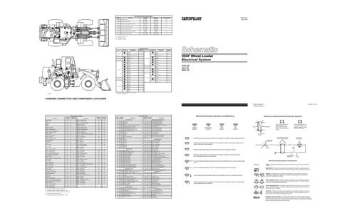
966F Wheel Loader Electrical System 4YG1-UP 3XJ1-UP 8BG1-UP
Vehicle locations are repeated for connectors located close together.
C32238P1
* = Connector is located at component.
HARNESS CONNECTOR AND COMPONENT LOCATIONS Printed in U.S.A.
©1990 Caterpillar All Rights Reserved
Machine Location 1
Machine Location 20
Wire Number
Wire Color
101
RD
102
Sensor - Hydraulic Temp
Alarm - Fault
E-3
C
Sensor - Trans Oil Temp
A-11
21
Alternator
E-10
2
Sensor - Trans Output Speed
B-1
22
Battery
F-12
3
Solenoid-A/C Clutch
E-10
23
Alarm - Backup
Schematic Location E-12
Component Location
Schematic Location A-2
Component
Component
Wire Description
Electrical Schematic Symbols And Definitions
Wire Number
Wire Color
BATTERY
419
YL
OPR MON PARKING BRAKE
BU
HEAD LAMP
429
YL
OPR MON BRAKE OIL TEMP
105
BR
KEY SW
432
PK
OPR MON BRAKE PRESS. (OIL)
107
WH
ENG SHUT-DOWN/AUTO FIRE SUPPR CONT
433
BU
OPR MON BRAKE PRESS. (OIL) JUMPER
109
OR
ALTERNATOR OUTPUT (+)TERM.
440
BR
AIR PRESS. GAGE
112
PU
MAIN POWER RELAY OUTPUT
441
OR
ENG COOLANT TEMP GAGE
Description Power Circuits
Monitoring Circuits (Continued)
Battery
E-12
4
Solenoid - Bucket Float
B-5
E
Breaker - Alternator
C-12
D
Solenoid - Bucket Kickout
B-5
E
Breaker - Blower Motors
B-5
E
Solenoid - Engine Shutdown
E-10
24
113
OR
OPR MON PANEL/VMIS B+ SWITCHED
442
GY
HYD SYSTEM TEMP GAGE
Breaker - Condenser Fan Motors
C-5
E
Solenoid - Lift Kickout
B-4
E
114
GN
WARNING HORN (FORWARD)
443
YL
POWER TRAIN TEMP GAGE
Breaker - Engine Shutdown
C-12
D
Solenoid - Ride Control
A-1
25
116
BR
AUX CKT
447
PK
FUEL LEVEL GAGE
Breaker - Main
C-12
D
Solenoid - Ride Control (German Roading)
D-1
25
118
GY
AUX CKT
450
YL
TACH SENDER (+)
Breaker - Running Lamp
C-12
D
Solenoid - Start Aid
A-11
26
120
YL
AUX CKT
496
WH
OPR MON PANEL HYD OIL LEVEL
Buffer - Fuel Level
C-2
5
Switch - Backup Alarm
B-2
A
121
YL
BACKUP ALARM/LAMP
A401
YL
ELECTRICAL SYSTEM VOLTAGE
Control - Engine Shutdown
C-10
6
Switch - Beacon
C-3
A
124
GN
A/C
A475
127
OR
AUX CKT
128
PK
AUX CKT
500
BR
WIPER - FRONT (PARK)
129
BU
AUX CKT
501
GN
WIPER - FRONT (LO)
130
GN
AUX CKT
502
OR
WIPER - FRONT (HI)
158
BR
AUX CKT
503
BR
WIPER - REAR (PARK)
177
OR
MAIN BKR
504
YL
WIPER - REAR (LO)
193
PU
AUX CKT
505
BU
WIPER - REAR (HI)
Converter - Voltage
F-4
A
Switch - Blower
F-7
A
Dryer-Brake Air
A-10
7
Switch - Brake Oil
C-1
27
Flasher
C-5
A
Switch - Brake Oil
C-2
27
Fuse - Holder
B-4
E
Switch - Bucket Positioner
A-1
28
Fuse - Holder
C-12
D
Switch - Bucket Positioner (German Roading)
D-1
28
Accessory Circuits
Ground - Engine To Frame
D-10
8
Switch - Dimmer
F-2
A
Ground - Cab To Frame
A-7
9
Switch - Disconnect
F-11
29
506
PU
WASHER - FRONT
200
BK
MAIN CHASSIS
507
WH
WASHER - REAR
Ground Circuits
Ground - Platform (Cab)
A-7
E
Switch - Engine Oil
A-12
30
201
BK
OPR MON PANEL/VMIS/CMS
508
PU
RADIO SPEAKER - LEFT
Horn - Forward (German Roading)
D-1
10
Switch - Ether Aid Coolant
A-12
31
203
BK
CHASSIS DIAGNOSTIC
509
WH
RADIO SPEAKER - LEFT (COMMON)
Lamp - Master Warning (CMS)
B-3
B
Switch - Flood Lamp
E-6
C
207
BK
STARTER DIAGNOSTIC
511
BR
RADIO SPEAKER - RIGHT
Meter - Service
E-7
A
Switch - Front Wiper
D-3
B
270
BK
CMS IDENT CODE 0
512
GN
RADIO SPEAKER - RIGHT (COMMON)
Monitor - Computerized System (CMS)
E-4
B
Switch - Horn
D-2
A
271
BK
CMS IDENT CODE 1
513
OR
A/C COMPRESSOR/REFRIGERANT PRESS. SW
Motor - Blower
D-8
E
Switch - Hydraulic Oil Level
A-2
32
272
BK
CMS IDENT CODE 2
514
PU
A/C CONDENSER MOTOR
Motor - Blower
E-8
A
Switch - Key Start
D-6
C
273
BK
CMS IDENT CODE 3
515
GY
BLOWER MOTOR (HI)
Motor - Front Washer
B-10
11
Switch - Lift Positioner
A-1
33
274
BK
CMS IDENT CODE 4
516
GN
BLOWER MOTOR (MEDIUM)
Motor - Front Wiper
E-3
A
Switch - Lift Positioner (German Roading)
D-1
33
275
BK
CMS IDENT CODE 5
517
BU
BLOWER MOTOR (LO)
Motor - Rear Washer
B-11
12
Switch - Parking Brake
C-1
34
290
BK
CMS TACH/SPDOM IDENT CODE 0
521
YL
A/C SW TO REFRIGERANT SW
291
BK
CMS TACH/SPDOM IDENT CODE 1
522
WH
A/C CLUTCH TO THERMOSTAT SW
292
BK
CMS TACH/SPDOM IDENT CODE 2
537
GN
TURN SIGNAL SW TO FLASHER
538
BR
HAZARD INDICATOR
592
BU
DC/DC CONVERTER POWER OUTPUT
Motor - Rear Wiper
E-6
A
Switch - Primary Steering
B-1
35
Motor - Starter
F-11
13
Switch - Rear Wiper
D-3
B
Basic Machine Circuits
Motors - Condenser Fan
A-5
E
Switch - Refrigerant
A-7
E
301
BU
STARTER NO.1 SOL
Receptacle - Auxiliary Start
F-11
14
Switch - Ride Control
C-3
B
302
OR
STARTER NO.1 RESISTOR TO DIAGNOSTIC
Relay - Condenser Fan
A-6
A
Switch-Running Lamp
D-6
C
304
WH
STARTER RELAY NO.1 OUTPUT
603
PK
ROTARY BEACON
Relay - Main
C-12
D
Switch - Secondary Brake Air Press
F-8
36
306
GN
604
OR
STOP LAMP
Relay-Start
C-12
D
Switch - Start Aid
D-6
C
STARTER RELAY COIL TO NEUT START SW OR KEY SW
308
YL
MAIN POWER RELAY COIL
605
YL
TURN LAMP - LEFT
A
AA
T
Pressure Symbol
Temperature Symbol
Level Symbol
Flow Symbol
Typical representation of a Deutsch connector. The plug contains all sockets and the receptacle contains all pins.
Receptacle
Plug
1 2
1 2
1
2
Typical representation of a Sure-Seal connector. The plugand receptacle contain both pins and sockets.
Pin or Socket Number Wire, Cable, or Harness Assembly Identification
Normally open switch that will close with an increase of a specific condition (temp-press-etc.).
Component Part Number
Single Wire Connector
Normally open switch that is closed due to an applied condition, and will open again with a specific decrease in that condition.
C
A
A 325-PK-14
Pin
AA 1
Wire Color
Socket
Normally closed switch that will open with an increase of a specific condition. 2
Normally closed switch that is open due to an applied condition, and will close again with a specific decrease in that condition.
9X-1123 325-PK-14
200-BK-14
Circuit Number Identification
Wire Gauge
Electrical Schematic Symbols And Definitions
The circle indicates that the component has screw terminals and a wire can be disconnected from it.
FUSE - A component in an electrical circuit that will open the circuit if too much current flows through it.
No circle indicates that the wire cannot be disconnected from the component.
REED SWITCH - A switch whose contacts are controlled by a magnet. A magnet closes the contacts of a normally open reed switch; it opens the contacts of a normally closed reed switch.
Lighting Circuits
Resistor - Blower Speed
D-8
A
Switch - Stoplamp
C-2
37
310
PU
START AID SW TO START AID SOL
606
GY
TURN LAMP - RIGHT
Resistor - Monitor System Voltage(CMS)
C-12
D
Switch - Supplemental Steering
B-2
38
311
WH
START AID SOL TO TEMP SW
608
GN
FLOOD LAMP - REAR
BR
BACKUP ALARM/LAMP/TRAVEL ALARM
610
OR
HEAD LAMP BASIC
Resistor - Starting System Diagnostics
F-10
15
Switch - Thermostat
E-7
A
321
Sender-Fuel Level
C-1
16
Switch - Trans Neutral
B-1
A
322
GY
WARNING HORN (FORWARD)
611
PU
HEAD LAMP HI
Sensor - Brake Air Pressure
C-1
17
Switch - Turn Signal
C-5
A
326
PU
KEY SW "C" TERM.
614
PU
PARK/TAIL/DASH LAMP
Sensor - Coolant Temp
B-12
18
327
PK
SHUTDOWN SOL
Sensor - Engine Speed
A-11
19
615
YL
CAB FLOOD LAMP/ROPS
Monitoring Circuits
617
BR
TAIL/POSITION LAMP - LEFT (ROAD PKG)/WIDTH
619
GN
HEAD LAMP LO
403
GN
ALTERNATOR (R) TERM.
405
GY
OPR MON OIL PRESS. (LO SETTING)
B = Components located in operator compartment - Dash.
409
OR
OPR MON NEUT
710
GN
XMSN SPEED PICKUP SIGNAL
C = Components located in operator compartment - Rt. Console.
410
WH
OPR MON FAULT ALARM
761
GY
LIFT KICKOUT SOL SW
D = Components located on relay panel.
411
PK
OPR MON MASTER FAULT LAMP
762
YL
BUCKET POSITIONER SOL SW
E = Components located in service compartment - At. Side.
416
OR
SUPPL STER SW
944
OR
CMS COMM+
417
GY
PRIMARY STER SW
945
BR
CMS COMM -
976
OR
RIDE CONT SOL
A = Components located in operator compartment.
Harness And Wire Electrical Schematic Symbols
Description
Control Circuits
This indicates that the component has a wire connected to it that is connected to ground.
This indicates that the component does not have a wire connected to ground. It is grounded by being fastened to the machine.
T
SENDER - A component that is used with a temperature or pressure gauge. The sender measures the temperature or pressure. Its resistance changes to give an indication to the gauge of the temperature or pressure. RELAY (Magnetic Switch) - A relay is an electrical component that is activated by electricity. It has a coil that makes an electromagnet when current flows through it. The electromagnet can open or close the switch part of the relay. CIRCUIT BREAKER (C/B) - A component in an electrical circuit that will open the circuit if too much current flows through it. This does not destroy the circuit breaker and it can be reset to become part of the circuit again. SOLENOID - A solenoid is an electrical component that is activated by electricity. It has a coil that makes an electromagnet when current flows through it. The electromagnet can open or close a valve or move a piece of metal that can do work. MAGNETIC LATCH SOLENOID - A magnetic latch solenoid is an electrical component that is activated by electricity and held latch by a permanent magnet. It has two coils (latch and unlatch) that make electromagnet when current flows through them. It also has an internal switch that places the latch coil circuit open at the time the coil latches.