SENR1391-02 August 2000
2
1
1
3
2
4 AA
3
6
5
4
7
5
6
7
8
9
10
11
12
BB
14
13
15 CC
A
16
17
18
19
A
DD
20
22
21
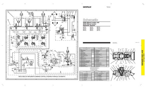
950G Wheel Loader and 962G Wheel Loader Hydraulic System
23
2JS1-UP 3BS1-UP 3JW1-UP 4BS1-UP 4PW1-UP
B
B
EE
FF
GG
HH
JJ
5AS1-UP 5FW1-UP 5MW1-UP 5RS1-UP 6EW1-UP
6HW1-UP 6NS1-UP 7BW1-UP 8JW1-UP BDP1-UP
KK LL
E2
MM
E6
E4
C
E1
C 24
25
26
27
Printed in U.S.A.
© 2000 Caterpillar All Rights Reserved
E3
E5
E7
D Chart C 950G and 962G Hydraulic Component Locations Item No.
NN 29
30
31
32
33
34 35
36
PP E
37
E
38
RR
SS
TT 39
UU
40
VV WW
41
42
43
44
45
46
47
48
49
50
Schematic Location
Item No.
Component
Schematic Location
1
Main Control Valve %
A1
27
Parking Brake Control Valve
C7
2
Auxiliary Cylinders @
A2
28
Steering Cylinders
D7 D4
3
Tilt Cylinder
A3
29
Steering Pilot Valve
4
Lift Cylinders
A4
30
Steering Wheel
5
Front Service Brakes
A5
31
Screen Group
6
Left Pedal Assembly
32
Check Valve
7
Right Pedal Assembly
33
Left Steering Neutralizer Valve
A6
Service Brake Control Valve
34
Steering Control Valve
9
Front Service Brakes Accumulator
35
Steering Crossover Relief Valve
10
Rear Service Brakes Accumulator
11
E5
Shuttle Valve
E7
Parking Brake
37
Hydraulic Oil Filter
E2
12
Parking Brake Actuator
38
Hydraulic Oil Cooler Bypass Valve
E3
13
Orifice
39
Steering Pump
E1
40
Hydraulic Oil Cooler
E3
41
Implement Pump
42
Pilot/Brake Pump
A3
14
Ride Control Diverter Valve #
15
Ride Control Accumulator #
16
Main Relief Valve
A5 A1
17
Line Relief Valve (Aux. Cylinder Head End) @
18
Line Relief Valve (Aux. Cylinder Rod End) @
19
Line Relief Valve (Tilt Cylinder Rod End)
20
Line Relief Valve (Tilt Cylinder Head End)
21
Rear Service Brakes
22
43
Fan Drive Pump
F2
Fan Drive Motor
F3
45
Shuttle Valve
F4
46
Secondary Steering Valve *
B5
47
Right Steering Neutralizer Valve
Accumulator Charging Valve
B6
48
Pressure Reducing Valve
F6
23
Parking Brake Pressure Switch
B7
49
Steering Backup Relief Valve
F7
24
Pilot Valve (Oil Manifold)
50
Secondary Steering Pump and Electric Motor*
F4
51
Breaker Relief Valve
52
Hydraulic Oil Tank
A3
C1
25
Lowering Control Valve
26
Service Brake Oil Pressure Switch
C6
52
43, TT
1, 13 - 20, 26
25
EE, FF, GG, HH, JJ, KK, LL
29, 32
NN
3
44
F5
34, 35, 37, 49, 51, 52, RR
39, 41, 42, XX
21
22, 23, 26, 27
46, 50 43, TT
28 7, 28, 31, 47, PP
4
5
2
34, 35, 49
28
39, 41, 42, XX
F1
* Secondary Steering is an optional attachment. # Ride Control is an optional attachment. @ Auxiliary Cylinders are an optional attachment. % The one stem valve (third function) is an optional attachment field conversion. The two stem valve is standard. The three stem valve is an optional attachment.
M
8, 28, 33, CC, DD, PP
9, 10, MM 22, 23, 26, 27
F1
44
A2
46, 50
E6
36
A7
38, 40
D5
8
F
F 51
Component
Chart C 950G and 962G Hydraulic Component Locations
20 Page, MDW
28
30
6, 7
8, 9, 10, CC, DD, MM, PP
1, 13 - 20, 26, EE, FF, GG, HH, JJ, KK, LL
AA, BB
3
44
XX Chart D 950G and 962G Hydraulic Pressure Tap Locations
Chart D 950G and 962G Hydraulic Pressure Tap Locations Pressure Tap
950G & 962G E/H IMPLEMENT/COMMAND CONTROL STEERING HYDRAULIC SCHEMATIC
G
G
E99208
125-9175-05
1
2
3
4
5
6
7
Description
AA
Tilt Cylinder Rod End Pressure
BB
Tilt Cylinder Head End Pressure
CC
Rear Service Brake Pressure
DD
Front Service Brake Pressure
EE
Auxiliary Pilot Pump Pressure
FF
Auxiliary Pilot Pump Pressure
GG
Tilt Pilot Pump Pressure
HH
Tilt Pilot Pump Pressure
JJ
Lift Pilot Pump Pressure
KK
Lift Pilot Pump Pressure
LL
Pilot Pump Pressure
Schematic Location A3
A5 B1 B2
Pressure Tap MM
C6
NN
D1
PP
Steering Pump Pressure
E1
RR
Fluid Sampling Valve
E2
SS
Steering Pilot Pressure
E6
TT
Fan Drive Pump Pressure
E3
B3
C5
Service Brake Accumulator Pressure
Schematic Location
Implement Pump Pressure
UU
C4
Description
Steering Control Valve Neutral Pilot Pressure
VV
Steering Pilot Pressure
WW
Steering Pilot Pressure
XX
Steering Pump Signal Pressure
SENR1391-02
D
E4 F4
21
F6
38, 40
37, 51, 52, RR
28 11, 12, NN
31, 47, PP
GG
5 4
2