Wire Description Wire Number
Connector Location ¹
5
Schematic Location
Machine Location
CONN 1
E-15
3
CONN 2
A-12
7
CONN 3
B-12
7
CONN 4
B-12
7
CONN 5
B-12
7
CONN 6
B-12
7
CONN 7
B-12
7
CONN 8
C-12
7
CONN 9
C-12
7
CONN 10
C-12
7
CONN 11
D-12,I-8
52
CONN 12
E-12,I-8
18
CONN 13
F-11
18
CONN 14
G-10
C
CONN 15
H-10
50
CONN 16 ECAP
A-8
7
CONN 17 Machine Harness Code
A-8,I-7
7
CONN 18 Options Code
A-8,I-8
7
CONN 19
G-6
A
CONN 20
G-6
A
CONN 21
G-6
A
CONN 22
D-2,I-5,I-6
55
CONN 23
D-2,I-5,I-6
55
CONN 24
A-5
54
CONN 25
B-5
54
CONN 26
D-5
A
CONN 27
E-5
A
CONN 28
E-5
A
CONN 29
E-5
A
CONN 30
E-2,I-2
22
Connector Number
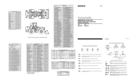
CONN 31 D-14 48 ¹The connectors shown in this chart are for harness to harness connectors. Connectors that join a harness to a component are generally located at or near the component. See the Component Location Chart.
57 34 45 49 51 29 43 50 14 38
30 15
25 35 32 58
4 10
20
36
3
44 28 6 40
1 8
37
59
17
2
47
52
C
27
21
50
12 13
53 19
9
52 17
49
7
B 48
10
29
4 6
38
28
3 1 5 8
32 58 36
40 4214 39 47 59 25
55 26
22
12
37 2044
56
53
57
35
24
33
31 A B 16 18 23 41 46 D 54
39 48 42
11
2 45
D
13
51
41
34 C 18 43 9
7 19
A
31 23
16
33 22
46 11 15 30
1
21 55
54 24 26 56
27
EO2385
Machine Harness Connector and Component Locations
Code Flashed 11
Diagnostic Code Conversion CID - FMI
No ACTIVE
Faults No
Description Not applicable. Not applicable.
12
INACTIVE
14
-
928G
15
-
Not Available
16
-
1T28G
17
-
Not Available
31
641 - 05
Forward High Solenoid Open Circuit
32
642 - 05
Reverse Solenoid Open Circuit
33
643 - 05
Forward Low Solenoid Open Circuit
34
644 - 05
Speed 1 Solenoid Open Circuit
35
645 - 05
Speed 2 Solenoid Open Circuit
36
646 - 05
Speed 3 Solenoid Open Circuit
37
346 - 05
Ride Control Relay Open Circuit
38
683 - 05
Parking Brake Alarm Open Circuit
39
421 - 05
Load Check Relay Open Circuit
41
641 - 06
Forward High Solenoid Short to Ground
42
642 - 06
Reverse Solenoid Short to Ground
43
643 - 06
Forward Low Solenoid Short to Ground
44
644 - 06
Speed 1 Solenoid Short to Ground
45
645 - 06
Speed 2 Solenoid Short to Ground
46
646 - 06
Speed 3 Solenoid Short to Ground
47
346 - 06
Ride Control Relay Short to Ground
48
683 - 06
Parking Brake Alarm Short to Ground
49
421 - 06
Load Check Relay Short to Ground
51
641 - 03
Forward High Solenoid Short to Battery
52
642 - 03
Reverse Solenoid Short to Battery
53
643 - 03
Forward Low Solenoid Short to Battery
54
644 - 03
Speed 1 Solenoid Short to Battery
55
645 - 03
Speed 2 Solenoid Short to Battery
56
646 - 03
Speed 3 Solenoid Short to Battery
57
346 - 03
Ride Control Relay Short to Battery
58
683 - 03
Parking Brake Alarm Short to Battery
59
421 - 03
Load Check Relay Short to Battery
61
190 - 08
Engine Speed Sensor
62
191 - 08
Transmission Speed Sensor
63
668 - 02
Invalid Shift lever Input
64
168 - 00
Battery Voltage Above Normal
65
168 - 01
Battery Voltage Below Normal
66
650 - 02
Invalid Harness Code Input
67
687 - 02
Invalid Option Code Input
68
367 - 02
Invalid Ride Control Switch Input
69
621 - 02
Invalid Downshift Switch
Faults
Component Location
Schematic Machine Location Location Alarm G-8 D Alarm - Backup F-15 1 Alternator E-15 2 Batteries - 12 Volt E-15 6 Breaker - Air Seat G-10 D Breaker - Alternator G-14 8 Breaker - Auxiliary G-14 8 Breaker - Lamp F-10 D Breaker - Main G-14 8 Cigar Lighter E-7 A Condenser Group B-14 15 Control - Autoshift Electronic (CST) A-7 10 Control - Secondary Steering A-6 10 Converter - 12 Volt to 24 Volt G-10 12 Defroster - Rear F-12 11 Diode Block H-6 B Diode Block As H-8 A Flasher F-6 A Fuses F-10 C Gauge - Coolant Temperature G-4 B Gauge - Fuel Level F-4 B Gauge - Hydraulic Temperature G-5 B Gauge - Speedometer F-4 B Gauge - Torque Converter Oil Temperature F-5 B Heater - Air Intake C-15 27 Heater - Seat I-9 A Horn - Forward E-1 13 LED Panel F-4 A Motor - Blower E-11 15 Motor - Sec Steer I-12 16 Motor - Starter E-14 26 Motor - Wiper (Front) E-4 26 Motor - Wiper (Rear) F-12 19 Motors - Washer Front and Rear C-3 17 Radio H-11 D Receptacle - Aux Start E-15 25 Relay - AIH (Air Intake Heater) C-14 8 Relay - Alarm Disarm D-10 12 Relay - Backup Alarm D-10 12 Relay - FNR E-11 C Relay - Main Power F-10 C Relay - Park Brake Alarm D-10 12 Relay - Ride Control D-10,I-10 12 Relay - Seat Alarm D-10 12 Relay - Sec Steer I-12 16 Relay - Start Aid (906) H-11 3 Relay - Start Aid (906) H-11 3 Relay - Start G-14 8 Relay/Driver - Remote FNR Control A-5 46 Resistor - Blower E-11 15 Sender - Fuel Level A-14 20 Component
Schematic Machine Location Location Sender/Switch - Coolant D-15 27 Sender/Switch - Hydraulic F-13 30 Sender/Switch - T/C Oil Temp D-13 24 Sensor - Engine Speed D-14 21 Sensor - Transmission Speed E-13 22 Service Meter G-6 B Shifter - CST H-5 B Solenoid - A/C Compressor D-15 3 Solenoid - Shutdown C-14 23 Solenoids - CST Valves E-13 24 Solenoids - Load Check Valve I-11 C Solenoids - Pilot Valve Group B-10 C Solenoids - Ride Control Valve I-10,I-11 4 Speedometer F-4 A Switch - A/C Compressor F-8 C Switch - A/C Refrigerant D-15 3 Switch - Beacon F-7 A Switch - Blower F-9 C Switch - Brake Pressure C-14 D Switch - Bucket Positioner E-1 , I-1 9 Switch - Bucket/Fork Selector E-8 C Switch - Defrost F-8 C Switch - Dimmer F-5 D Switch - Disconnect D-15 28 Switch - Downshift B-9 C Switch - Engine Oil Pressure C-14 29 Switch - Forward Horn F-6 B Switch - Hydraulic Lock Detent Override F-8 A Switch - Key Start F-6 B Switch - Kickout On/Off E-8 C Switch - Lamp H-6 A Switch - Lamp Test G-7 A Switch - Lift Positioner E-1, I-1 14 Switch - Remote FNR A-9 B Switch - Ride Control E-8 C Switch - Ride Control Interupt/Tilt Pressure I-10 C Switch - Sec Steer Manual D-7 A Switch - Service Brake C-4 D Switch - Start Aid F-7 A Switch - Steering Pressure D-13 4 Switch - Thermostat E-11 23 Switch - Turn Signal F-5 B Switch - Wiper I-9 A Switch - Wiper (Front) D-7 A Switch - Wiper (Rear) C-7 A Switch - XMSN Auto/Manual D-8 C Switch - XMSN Neutral C-4 D Switch - XMSN Neutralizer F-7 A Switch/Sender - Hydraulic F-13 30 Switch/Sender - T/C Oil Temp D-13 24 Timer - Start Aid G-8 D
Machine locations are repeated for components located close together. A = Operator Compartment - Dash Console. B = Operator Compartment - Steering Column. C = Operator Compartment - Relay/Fuse Panel. D = Operator Compartment - Right Console.
Component
Wire Color
Description
Wire Number
Wire Color
Power Circuits
Accessory Circuits (Continued)
101 102 105 108 109 112 114 115 117 118 120 122 123 124 126 127 128 129 130 135
RD BU BR BU OR PU GN PK YL GY YL BU WH GN PK OR PK BU GN BU
Bat(+) HdLmp KeySw Aux Ckt Alt Output (+) Term. Main Power Rly Output Warning Horn (Forward) AuxCkt AuxCkt AuxCkt AuxCkt AuxCkt Aux Ckt A/C Xmsn Ctrl Aux Ckt AuxCkt Aux Ckt Aux Ckt Aux Ckt
506 507 508 509 511 512 513 515 516 517 521 522 537 538 567 571 593 A514 A519 A520
PU WH PU WH BR GN OR GY GN BU YL WH GN BR WH OR GN YL GN BU
136
GN
Suppl Ster
A538
OR
140 144 158 160 188
BU GN BR PU WH
A576
GN
200 202 276 277 278 279 A221 A222 A232
BK BK BK BK BK BK BK BK BK
603 604 605 606 608 61611 614 615 619 665 667
PK OR YL GY GN OR PU PU YL GN BR OR
301 304 306 307 308 310 321 322 326 331 373
BU WH GN OR YL PU BR GY PU OR GN
Aux Ckt AuxCkt AuxCkt AuxCkt Aux Ckt Ground Circuits Main Chassis XMSN Ctrl XMSN Ctrl Ident Code 0 XMSN Ctrl Ident Code 1 XMSN Ctrl Ident Code 2 XMSN Ctrl Ident Code 3 XMSN CtrI Options Code 0 XMSN CtrI Options Code 1 XMSN CtrI Options Code 2 Basic Machine Circuits Starter No. 1 Sol Starter Relay No. 1 Output
403 404 405 406 417 419 441 442 443 447 449 450 453 483 484 C444 C445 C446 C470 C471 E417 E419
GN YL GY PU GY YL OR GY YL PK BU YL PK BR YL YL BU PK BR GN OR BU
500 501 502 503 504 505
BR GN OR BR YL BU
702 710 720 727 751 752 754 755 761 762 E701 F748 F765 F766 G728 G742 G750 G755 G760 G761 G762 G763 G768 G787 G788 G797 E800 F853 F880 900 901 944 945 963 964 973 975 976 978 C904 C920 P914 P915 P916
OR GN PU GN GN YL BU OR GY YL PK WH BR WH YL GN BU GY WH YL BR PU GN GN YL BU GN BR BR PU WH OR BR GN BU BR WH OR GN GN GY GN PK OR
Starter Relay Coil To Neut Start SW Or Key SW
Key SW To Neut Start SW Main Power Relay Coil Start Aid SW To Start Aid Sol Backup Alarm Lamp Travel Alarm Warning Horn (Forward) Key SW "C" Term. Backup Alarm Relay Coil Start Aid Switch To Timer Monitoring Circuits Alternator (R) Term. Opr Mon Hyd Oil Temp Opr Mon Oil Press. (Low Setting) Opr Mon Coolant Temp Primary Ster SW Opr Mon Parking Brake Eng Coolant Temp Gauge Hyd System Temp Gauge Power Train Temp Gauge Fuel Level Gauge Spdom Sender (Signal No. 1) Tach Sender (+) Suppl Ster Fault Lamp Brake Fluid Level Primary Ster Lamp Alternator Indicator Lamp Alarm To Diode Pack Power Train Filter Warning Relay Contact To Alarm Relay Contact To Indicator Lamp Park Brake SW #2 Seat Alarm Power Accessory Circuits Wiper - Front (Park) Wiper - Front (Low) Wiper - Front (HI) Wiper - Rear (Park) Wiper - Rear (Low) Wiper - Rear (HI)
SENR1277 June 1998
Description
Washer - Front Washer - Rear Radio Speaker - Left Radio Speaker - Left (Commom) Radio Speaker - Right Radio Speaker - Right (Common) A/C Compressor/Refrigerant Pressure SW
Blower Motor (HI) Blower Motor (Medium) Blower Motor (Low) A/C SW To Refrigerant SW A/C Clutch To Thermostat SW Turn Signal SW To Flasher Hazard Indicator A/C SW Jumper Dozer Float Sol/Bucket Condensor Fan Relay To Motors SW To Relay Coil Axle Suspension Sol Valve Relay To Axle Suspension Rocker SW Rear Window Defroster (Resistive Element In Glass) Breaker To Compressor (Air Seat) Lighting Circuits Rotary Beacon Stop Lamp Turn Lamp - Left Turn Lamp - Right Flood Lamp - Rear Head Lamp Basic Head Lamp Hi Park/Tail/Dash/Lamp Cab Flood Lamp/Rops Head Lamp Lo SW To Left Front / Right Rear Lights Front Floods - Aux Control Circuits XMSN Brake SW Jumper XMSN Speed Pickup Signal XMSN Brake SW Suppl Ster Motor Relay XMSN Shift Sol No. 1 Or 3 XMSN Shift Sol No. 2 XMSN Shift Sol No. 3 Or 1 XMSN Shift Sol No. 4 Or 5 Lift Kickout Sol SW Bucket Positioner Sol SW Auto Ride Cntl SW Ride Ctrl SW To HTC Park Brake SW To Relay Kickouts/Detent Disable SW To Kickouts SW To SW (Generic) Relay Coil to Diode XMSN Cont Fwd SW To Gnd XMSN Cont Rev SW To Gnd XMSN Cont Speed 2 SW To Gnd XMSN Cont Speed 3 SW To Gnd XMSN Cont Speed 4 SW To Gnd XMSN Cont Neut SW To Gnd XMSN Cont Speed 1 SW To Gnd XMSN Cont Remote Fwd SW To Gnd XMSN Cont Remote Rev SW To Gnd SW To Relay Coil Seat Alarm To Diode Pack Travel Speed Diode Block To Relay Contact XMSN Shift Sol No. 5 or 4 XMSN Shift Sol No. 6 Data Link + (CAT) Data Link - (CAT) Bucket/Fork Position Detent Coil Fork Position Select CST Autoshift - Auto/Manual SW 2 CST Autoshift - Sol Return Ride Cont Sol 1 CST Autoshift - Slow Mode SW 1 Relay to Relay Fault Lamp - control XMSN Forward Indicator XMSN Neutral Indicator XMSN Neutral Switch
928G Wheel Loader and IT28G Integrated Toolcarrier Electrical System 928G: 6XR01074-UP 7SR00702-UP
IT28G: 8CR01162-UP 9AR00372-UP
Printed in U.S.A.
© 1998 Caterpillar All Rights Reserved
Harness And Wire Electrical Schematic Symbols A
AA
Electrical Schematic Symbols And Definitions
Typical representation of a Deutsch connector. The plug contains all sockets and the receptacle contains all pins.
Receptacle
Plug 2
Part No.
Resistor, Sender and Solenoid Specifications Component Description
T
Resistance (Ohms)¹
3E-1906
Solenoid - A/C Compressor
17.6±0.6
3E-6269
Solenoids - CST Valves Solenoid - Engine Shutdown Latch: Unlatch: Resistor - Heater Group
33.8±1.0
8C-3663 9G-1950 104-3007
Sender/Switch - Torque Converter Oil Temp
104-3008
Sender/Switch - Hydraulic Oil Temperature
118-5144
Sender/Switch - Coolant Temp
122-1134
Sender - Fuel Level Full: Empty: Solenoids - Load Check Valve
134-9878
Solenoid - Ride Control Valve
119-0102
Function
27.5 - 39.5 240 - 260
Actuate
Deactuate
Related Electrical Service Manuals Alternator: 9W-3043
Wire, Cable, or Harness Assembly Identification
Form Number SENR3685
Electric Starting Motor: 106-8558 Consist: 106-8557 Consist: 106-8559
SENR3559 SENR3581
Transmission Electronic Control System
SENR1218
Component Part Number
Single Wire Connector C
A
A 325-PK-14
Normally open switch that will close with an increase of a specific condition (temp-press-etc.). Pin
Normally open switch that is closed due to an applied condition, and will open again with a specific decrease in that condition.
AA 1
9X-1123 325-PK-14
Wire Color
Socket
2
200-BK-14
Circuit Number Identification
Normally closed switch that will open with an increase of a specific condition.
Wire Gauge
Electrical Schematic Symbols And Definitions
Normally closed switch that is open due to an applied condition, and will close again with a specific decrease in that condition.
Primary Steering Pressure (EMS)
Typical representation of a Sure-Seal connector. The plug and receptacle contain both pins and sockets.
Pin or Socket Number
Flow Symbol
41.9 13.8 ± 0.4
Off Machine Switch Specification
Title
Level Symbol
Overall 2.0±1; Tap 1.0±05 465 to 586 @ 115.6 °C (240.1 °F) 5870 to 7459 @ 54.4 °C (129.9 °F) 5870 to 7459 @ 54.4°C (130°F) 465 to 586 @ 115.6°C (240°F) 465 to 586 @ 115.6 °C(240.1 °F) 5870 to 7459 @ 54.4 °C (129.9 °F)
FUSE - A component in an electrical circuit that will open the circuit if too much current flows through it.
Contact Position
1200 kPa MAX 700 ± 100 kPa A-C, Normally Closed (175 psi MAX) (100 ± 15 psi) A-B, Normally Open 10700 kPa MAX 8960 ± 345 kPa A-B, Normally Open 3E-7693 Service Brake Oil Pressure (1550 psi MAX) (1300 ± 50 psi) A-C, Normally Closed 129.0 ± 3.0 °C 112 °C 104-3007 Torque Cony Oil Temp Sender Normally Open (264.2 ± 5.4 °F) (233.6 °F) 102.0 ± 3.0 °C 90 °C( 104-3008 Hydraulic Sender Normally Open (215.6 ± 5.4 °F) 194.0 °F) 275 to 1750 kPa ¹ 114-5333 Refrigerant Pressure (AC) Normally Open ¹ (40 to 255 psi) 107 ± 3°C 95°C 118-5144 Coolant Sender Normally Open (224.6 ± 5.4 °F) (203.0 °F) 255 kPa MAX 205 ± 20 kPa A-B, Normally Open 126-6916 Ride Control Interupt-Tilt Pressure (37 psi MAX) (29.8 ± 2.9 psi) A-C, Normally Closed ¹ A hysteresis band exists: with increasing pressure the closed condition can be maintained up to 2800 kpa (405 psi), with decreasing pressure the closed condition can be maintained down to 170 kpa (25psi). 3E-6450
Temperature Symbol
1.55±0.15 10.3 ± 1.03
¹ At room temperature.
Part No.
Pressure Symbol
1 2
1 2
1
The circle indicates that the component has screw terminals and a wire can be disconnected from it.
REED SWITCH - A switch whose contacts are controlled by a magnet. A magnet closes the contacts of a normally open reed switch; it opens the contacts of a normally closed reed switch.
No circle indicates that the wire cannot be disconnected from the component.
SENDER - A component that is used with a temperature or pressure gauge. The sender measures the temperature or pressure. Its resistance changes to give an indication to the gauge of the temperature or pressure.
This indicates that the component has a wire connected to it that is connected to ground.
This indicates that the component does not have a wire connected to ground. It is grounded by being fastened to the machine.
T
RELAY (Magnetic Switch) - A relay is an electrical component that is activated by electricity. It has a coil that makes an electromagnet when current flows through it. The electromagnet can open or close the switch part of the relay. CIRCUIT BREAKER (C/B) - A component in an electrical circuit that will open the circuit if too much current flows through it. This does not destroy the circuit breaker and it can be reset to become part of the circuit again. SOLENOID - A solenoid is an electrical component that is activated by electricity. It has a coil that makes an electromagnet when current flows through it. The electromagnet can open or close a valve or move a piece of metal that can do work. MAGNETIC LATCH SOLENOID - A magnetic latch solenoid is an electrical component that is activated by electricity and held latch by a permanent magnet. It has two coils (latch and unlatch) that make electromagnet when current flows through them. It also has an internal switch that places the latch coil circuit open at the time the coil latches.