B
BASIC COMPONENT SYMBOLS
TAP LOCATIONS
COMPONENT LIST Tap
Item Number
Part Number
Description:
1 2 3 4 5 6 7 8 9 10 11 12 12A
247-7867 245-8777 214-2202 210-6243 247-7868 214-5097 228-3508 206-3553 185-1839 N/A 285-1170 285-1171 N/A
PUMP GP - PISTON TANK GP - MTG COOLER FILTER PUMP GP - METERING FRONT STEER CYL. LIFT CYL. ST TILT CYL. ST MP BUCKET CYL. AUXILIARY CYLINDER PITCH CYLINDER (3 POINT) TILT CYLINDER (3 POINT) DUAL TILT CYL OPT. (3 POINT)
13 14
285-1172 285-1187
15
248-0481 248-0482 259-6732 259-6745 259-6731 259-6729 245-8780 131-9203 162-3960 8J-6875
LIFT CYLINDER (3 POINT) IMPLEMENT VALVE GROUP LOADER VALVE LOADER VALVE (ST) 2-BANK LOADER VALVE (ST) 3-BANK LOADER INLET LOADER LIFT VALVE LOADER TILT VALVE LOADER AUXILIARY (MP) RIDE CONTROL VALVE PRESSURE SWITCH RIDE CONTROL ACCMLTR VALVE AS - SHUTTLE
15A 15B 15C 15D 16 17 18 19
FLUID POWER SYMBOLS
KENR6654 August 2006
MAIN AUX.
Description
T1 T2 SOS
A
Pump Discharge Load Sense Oil Sampling
PUMP or MOTOR
C
LINE RESTRICTION (FIXED)
RESTRICTION
PRESSURE COMPENSATION
LINE RESTRICTION (VARIABLE)
SPRING (ADJUSTABLE)
VARIABILITY
CONTROL VALVES
SPRING
FLUID CONDITIONER
PUMP: VARIABLE and PRESSURE COMPENSATED
2-SECTION PUMP
HYDRAULIC PNEUMATIC ENERGY TRIANGLES
ATTACHMENT
LINE RESTRICTION VARIABLE and PRESSURE COMPENSATED
VALVES VALVE ENVELOPES
D
VALVE PORTS
TWO POSITION
ONE POSITION
TWO-WAY
THREE POSITION
CONTROL VALVES
CHECK VALVES
AB
AB
P T SHIFTED POSITION
P T NORMAL POSITION
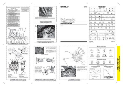
Travel at high speeds over rough terrain causes bucket movement. The optional Ride Control System acts as a shock absorber by absorbing bucket forces, which stabilize the machine.
FOUR-WAY
THREE-WAY
INFINITE POSITION
SHUTTLE
SPRING LOADED
BASIC SYMBOL
MEASUREMENT
PILOT CONTROLLED
ROTATING SHAFTS
The Ride Control System components include; ride control relay (A), ride control solenoids (B), ride control accumulator (C), and ride control pressure switch (D). Two solenoids are now used on the "E" Series machines Ride Control System.
RIDE CONTROL
PRESSURE
UNIDIRECTIONAL
BIDIRECTIONAL
FLUID STORAGE RESERVOIRS
414E Backhoe Loader Hydraulic System
16
FLOW
TEMPERATURE
VENTED
RETURN ABOVE FLUID LEVEL
PRESSURIZED
RETURN BELOW FLUID LEVEL
COMBINATION CONTROLS
ELB1-UP SOLENOID or MANUAL
SOLENOID
SOS
NOTE: Numbers15A through 15D are represented by the number 15 only on the machine views.
11
SERVO
SOLENOID and PILOT or MANUAL
SOLENOID and PILOT
DETENT
THERMAL
MANUAL CONTROL SYMBOLS
2
7
3
8 PUSH-PULL LEVER
MANUAL SHUTOFF
GENERAL MANUAL
PUSH BUTTON
PEDAL
SPRING
PILOT CONTROL SYMBOLS RELEASED PRESSURE
REMOTE SUPPLY PRESSURE
Pressure Switch EXTERNAL RETURN
INTERNAL RETURN
SIMPLIFIED
CROSSING AND JOINING LINES
ACCUMULATORS
SPRING LOADED
GAS CHARGED
LINES CROSSING
HYDRAULIC PUMPS FIXED DISPLACEMENT
The hydraulic oil filter is located below the machine at the left frame rail. The hydraulic oil filter bypass switch is mounted to the oil filter base.
13 12
14
19
15 4
1
18 17 16
5
6
HYDRAULIC OIL FILTER
9
HYDRAULIC AND PNEUMATIC CYLINDERS
SINGLE ACTING
LINES JOINING
FIXED DISPLACEMENT
VARIABLE DISPLACEMENT NON-COMPENSATED
UNIDIRECTIONAL
UNIDIRECTIONAL
BIDIRECTIONAL
BIDIRECTIONAL
DOUBLE ACTING
INTERNAL PASSAGEWAYS
HYDRAULIC MOTORS
VARIABLE DISPLACEMENT NON-COMPENSATED
INTERNAL SUPPLY PRESSURE
COMPLETE
FLOW IN ONE DIRECTION
PARALLEL FLOW
CROSS FLOW
FLOW ALLOWED IN EITHER DIRECTION
Printed in U.S.A.
© 2006 Caterpillar All Rights Reserved
4
TWO POSITION
THREE POSITION
INFINITE POSITIONING
COMPONENT LOCATIONS Electrical Symbols Table
TILT The implement and steering pump on the 414E is a similar design and operates the same as the pump on the "A" Series machines.
LIFT
E D
The pump is located below the cab floor plate. The pump control valve is mounted on top of the pump and contains a flow compensator spool and pressure cutoff spool. The implement and
PITCH
G
C Transducer (Fluid)
Transducer (Gas / Air)
Implement and Steering Pump
Pressure Switch (Adjustable)
T2
T2
D
A
B
H
A
Electrical Symbols (Electrical)
B LOAD SENSE
J
INLET PORT
A
F
T
K
C
Electrical Wire
Temperature Switch
STEERING PORT
C
T1
Pressure Symbol
Temperature Symbol
Flow Symbol
Level Symbol
TANK PORT
Wire Number Identification Codes
B
A
Pressure Cutoff (A), Flow compensator (B), Load sensing pressure tap (T2), Discharge pressure tap (T1), Inlet port (C), Case drain port (D), Hydraulic Oil Tank (E), Outlet port (F)
D
L
(A) Pump port (B) Inlet manifold (C) Tank port (D) A port (E) Control valve for the Auxiliary (F) Control valve for the Pitch
L
(G) Control valve for the Tilt (H) Control valve for the Lift (J) B port (K) Load signal port (L) Handle for the manual override
IMPLEMENT VALVE
The 414E is equipped with a mechanically controlled loader valve (A). The loader valve is accessed from below the floor plate.
Hydraulic Oil Filter
These illustrations show the implement and steering pump out of the machine. The following components are visible:
SOS
Electrical Schematic Example
Harness identification code This example indicates wire 135 in harness "AG".
Wire Circuit Number Identification
Wire Color
325-AG135 PK-14 325-PK Circuit Identification Number
T2
Wire Color
Wire Gauge
E F
Previous Standard T1
D
Wire Color
Wire
325-PK-14 B Circuit Number Identification
14
Current Standard
Current Standard
C
The loader control valve group contains an inlet manifold (B), lift control valve (C), tilt control valve (D), and auxiliary control valve (E, if equipped).
Hydraulic Schematic Example
IMPLEMENT / STEERING PUMP
1
LOADER VALVE
15
A
Wire Gauge (EXAMPLE VALVE)
(Print Size 34 x 24 inches)
G
F
Electric Motor
16 Page
E
Generator
B
Pressure Switch
A
M
WORK PORTS
VIEW OF AREA - A
3-Point Hitch
Hydraulic Symbols (Electrical)
KENR6654
DUAL TILT CYLINDER OPTION