SENR6243-01 October 2008
23
25
13 36
33
34
35 37
40
7
28 35
2
3
34
42
13 3 14 38 39
11
10
47
29 43
1
31
A
3
1
2 4
5
43
26
23
1 3
9 8
H
30
6
21
31
6
E
20
22
G
8 9
12 22
25
19
3
36
9
1 10 6 5 D
41 42
F
AREA G
AREA E
28 5
44
31 32
7
17
4
45 11
9
42
27
14
35
16
41 42
31 23
20
H 28
34
25
25
33
12 36 3
29
24
G
6
35
13
17 F
15
1 23 9
37
20
A
B
1
26
D 22
1
8 13 3
46
2
3
C 6
44
22
36 34
30
2
12
40 21 19
37 16
43
7
39
19
40 14 38
45 39
1
5 E
2
33 29 10 18
Machine Location
CONN 1
F-18
23
CONN 2
F-17
29
CONN 3
E-17
4F
CONN 4
E-17
35
CONN 5
C-16
36
CONN 6
C-16
1D
CONN 7
D-16
4
CONN 8
E-13
4A
18
B
16
Schematic Location
Connector Number
7
45
4
24
47
33
Connector Location
43 14
46
45
11 17 27
16
20
40
5
17
C
19
39
12 32
1
13
44
29 28
37
44
46
15
2
11
10
47
43
1
46
3 3
4
CONN 9
E-13
3A
CONN 10
E-13
3A 5D
CONN 11
A-13
CONN 12
E-12
2B
CONN 13
E-12
1B
CONN 14
F-12
2C
CONN 15
F-12
1C
CONN 16
B-11
6D
CONN 17
F-9
19
CONN 18
C-4,E-9
3
CONN 19
E-9
14
CONN 20
C-9
22
CONN 21
B-8
2D
CONN 22
C-4,D-8
4E
CONN 23
F-7
13
CONN 24
D-7
1E
CONN 25
D-7
2E
CONN 26
D-7
3E
CONN 27
B-7
4D
CONN 28
B-7
2D
CONN 29
B-7
3D
CONN 30
B-6
4D
CONN 31
D-6
6E
CONN 32
C-4
9B
CONN 33
E-4
19
CONN 34
C-3
39
CONN 35
C-3
39
CONN 36
B-3
20
CONN 37
B-2
20
CONN 38
C-2
39
CONN 39
D-2
3
CONN 40
D-2
3
CONN 41
E-2
1
CONN 42
F-1
18
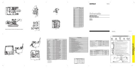
330 Excavator Electrical System 6ZK64-UP 8CK206-UP 2EL332-UP
The connectors shown in this chart are for harness to harness connectors. Connectors that join a harness to a component are generally located at or near the component. See the Component Location Chart. 5
6
4
Machine Harness Connector and Component Locations
AREA H
AREA F Printed in U.S.A.
© 2008 Caterpillar All Rights Reserved
Electrical Schematic Symbols And Definitions Symbols
Real Time Error Codes Code
Component Actuator - Governor Alarm - Action
7
2
4
5
6
10
3
5 6
8
1
2
3 7
4
8
9
7
5 8 9
3
4
AREA C
4 1
1
2
6
3
3
4
2
7
AREA B
3 4
8
AREA A 5
1
2
3
4
1
6
5
3
Solenoid - Combined
F-1
8
Antenna
E-14
4
Solenoid - Engine Pump Control
A-15
4H
Batteries
A-5
5
Solenoid - Engine Shutdown
B-17
21
Block - Terminal
B-7
1D
Solenoid - Fine Swing
C-9
22
Breaker - Alternator
A-12
5D
Solenoid - Hammer Control
D-1
23
B-13
6
F-2
3C
D-5
2B
Solenoid - Hammer Control Solenoid - Level/Finish Solenoid - Start Aid
D-2
43
B-15
1H
F-16
25
Diode Assembly
C-2
33
Solenoid - Travel Speed
A-15
3H
Diode - Main Relay
C-12
4D
Solenoid - Trenching
A-15
2H
Switch - Throttle Position
D-5
3B
Switch - AS. Rocker
B-3
8B
B-9,10,12
7D
Switch - ATCH Pressure
B-1
8
A-2
8
Switch - Backup ACCEL
E-11
6B
A-2,B-2
9
Switch - Boom Raise Pressure
D-15
3G
Lamp - Cab
E-1
43
Switch - Control
F-10
5C
Lamp - Chassis
A-2
10
Switch - Disconnect
A-6
6D
E-5
2A
Switch - EPR Valve Backup
F-11
2C
Meter - ATCH Service
D-1
46
Switch - Engine Oil Pressure
C-18
31
Instrument Panel
E-5
4A
Switch - Fine Swing Control
F-10
4C
F-2
11
Switch - Governor Backup
E-12
7B
Motor - Starter
B-17
12
Switch - Hammer Control
D-4
Motors - Washer
F-16
13
Switch - Hammer Foot
C-1
33
Motor - Upper Wiper
F-2
14
Switch - Horn
F-2
3C
Pump - Refueling
F-17
15
Switch - Implement Pressure
D-15
1G
5B
Relay - Boom Lamp
A-10
8D
Switch - Key
E-9
1B
Relay - Chassis/Cab Lamp
A-12
8D
Switch - Limit
F-1
8
Relays - Dual H.P.
A-9, A-10
8D
Switch - One Touch Low Idle
D-5
2B
Relay - Fine Swing
A-12
8D
Switch - Neutral Start
F-6
33
Relay - Horn
B-9
8D
Switch - Refrigerate Low Pressure
E-18
34
Relay - Main
C-12
4D
Switch - Refueling
E-16
35
Relay - Main (Attachment)
A-11
4D
Switch - Refueling Pump Start
E-17
13
Relay - Refueling Pump
A-9
8D
Switch - Refueling Pump Stop
F-17
36
Relay - Start
B-10
3D
Switch - Safety Pressure
C-1
33
Relay - Washer
B-10
8D
Switch - Seat Heater
F-10
5C
Relay - Wiper
B-12
8D
Switch - Start Aid
D-5
4B
Resistor - Backup
F-12
1C
Switch - Start Aid Coolant Temp
D-17
37
D-2
46
Switches - Travel Pressure
F-5
47
RPM Regulator Seat - Heater
F-13
45
Switch - Windshield
E-5
11
Sensor - Engine Coolant Temp
D-18
16
Unit - Air Conditioner
F-14
40
Sensor - Engine Speed
C-18
19
Sensor - Fuel Level
F-16
1F
Machine locations are repeated for components located close together.
AREA D
20
D-17
Motor - Lower Wiper 2
E-18
Alternator
Meter - Service
1
Solenoid - A/C Compress Clutch
5H 43
Lamps - Boom
6
3A
B-14 D-2
Horns
10
E-5
Sensor - Hydraulic Oil Temp Solenoid - Boom Down
Fuse - Block
1
1
Machine Location
2
Control Group - RH
6
C-13
Component
Schematic Location
E-17
Control Group - LH
7
Machine Location
Alarm - Travel
Control - Engine Pump
1 9 4
Schematic Location
Unit - Heater
F-13
44
E00
No problem.
E1
Engine oil pressure to low.
E2
Engine coolant temperature is to high.
E3
Hydraulic oil temperature is to high.
E4
Battery voltage is to high.
E5
Alternator terminal R is open.
E6
Speed sensor is not installed correctly or it's circuit is open.
E7
Engine speed is not normal.
T
Pressure Symbol
Off Machine Switch Specification Part No.
E11
Governor actuator feedback sensor circuit is shorted to body ground.
E12
Governor actuator feedback sensor voltage is not stable.
E13
Governor actuator motor circuit is shorted to body ground.
E14
Governor actuator motor does not rotate or motor circuit is shorted to battery voltage.
E15
Governor backup switch is in "Man" (backup) position or governor actuator motor circuit is open.
E16
Proportional reducing valve circuit is shorted to body ground.
E17
Proportional reducing valve circuit is shorted to battery voltage.
E18
Proportional reducing valve circuit is open.
E25
Engine coolant temperature sensor circuit is shorted to body ground.
E26
Engine coolant temperature sensor circuit is shorted to battery voltage or open.
490.0 ± 49.0 kPa MAX 290 kPa MIN Normally Open (71.0 ± 7.1 psi MAX) (42.0 psi MIN) 93 ± 21 kPa 69 ± 21 kPa 1-3,Normally Closed 9X-4276 Engine Oil Pressure (13.5 ± 3.0 psi) (10.0 ± 3.0 psi) 1-2,Normally Open 37.8 ± 2.8°C 26.7°C MIN 8C-3569 Engine Coolant Temp (Start Aid) Normally Closed (100 ± 5°F) (80°F MIN) Implement Pressure 1225 ± 343 kPa 735 kPa MIN 102-8041 Normally Open Safety Pressure (178 ± 50 psi) (107 psi MIN) 2450 ± 441 kPa 1470 kPa MIN 102-8042 Boom Raise Pressure Normally Open (355 ± 64 psi) (213 psi MIN) _ 275to1750kPa¹ 114-5334 Refrigerant Pressure (A/C) Normally Open ² _ (40 to 255 psi) ¹ With increasing pressure the closed condition can be maintained up to 2800 kpa (405 psi), with decreasing pressure the closed condition can be maintained down to 170 kpa (25psi).
E27
Hydraulic oil temperature sensor circuit is shorted to body ground.
² Contact position at the contacts of the harness connector.
E28
Hydraulic oil temperature sensor circuit is open or shorted to battery voltage.
E31
Controller receives signal of engine speed other than specified ten from engine speed dial.
E32
There is more than 100 rpm difference between dial setting and actual rpm.
E33
Digital output circuit is shorted to battery voltage.
E34
Governor actuator remains deactivated an elapsed time of 2.5 seconds after speed dial setting.
E36
Monitor takes at least 1 second to respond to controllers signal.
E37
Monitor RAM (Random Access Memory) is not normal.
E38
Controller is informed of it's error signal by monitor.
4I-5387
Controller detects it's error signal by it's self. Error in controller memory.
E41
A controller for a different machine is installed or harness cord problem.
E48
Engine stalls.
Switch (Normally Closed): A switch that will open at a specified point (temp, press, etc.). No circle indicates that the wire cannot be disconnected from the component. Ground (Wired): This indicates that the component is connected to a grounded wire. The grounded wire is fastened to the machine. Ground (Case): This indicates that the component does not have a wire connected to ground. It is grounded by being fastened to the machine. Reed Switch: A switch whose contacts are controlled by a magnet. A magnet closes the contacts of a normally open reed switch; it opens the contacts of a normally closed reed switch. Sender: A component that is used with a temperature or pressure gauge. The sender measures the temperature or pressure. Its resistance changes to give an indication to the gauge of the temperature or pressure.
T
Component Description
102-8016
Resistor:
Backup
47.0 ± 2.4
116-4416
Solenoid:
Hammmer Control
33.7 ± 1.0
117-6319
Solenoid:
A/C Clutch Compressor ¹
3E-7985
Solenoid:
Engine Shutdown
4I-5394
Sender:
5I-8368
Solenoid:
7Y-3848
Sender:
9G-4365
Solenoid:
Hydraulic Oil Temperature Engine Pump Control Fuel Level Start Aid
Relay (Magnetic Switch): A relay is an electrical component that is activated by electricity. It has a coil that makes an electromagnet when current flows through it. The electromagnet can open or close the switch part of the relay.
Resistance (Ohms)¹
Solenoid: A solenoid is an electrical component that is activated by electricity. It has a coil that makes an electromagnet when current flows through it. The electromagnet can open or close a valve or move a piece of metal that can do work.
14.4 ± 0.6 Latch Coil; 1.55 ± 0.16 Unlatch Coil; 10.3 ± 1.0 6134 to 7496
MAGNETIC LATCH SOLENOID - A magnetic latch solenoid is an electrical component that is activated by electricity and held latched by a permanent magnet. It has two coils (latch and unlatch) that make electromagnet when current flows through them. It also has an internal switch that places the latch coil circuit open at the time the coil latches.
11.7 ± 0.6 Empty: 83.5 ± 1.5 Half: 33.8 ± 2.0 Full: 8 0 (+ 1 0) (- 0 5) 6
Harness And Wire Symbols
¹ At room temperature unless otherwise noted.
Wire, Cable, or Harness Assembly Identification Pin
Socket
Fuse
Wire Color
A
Component Part Number
AA
105-9344
1
325-PK-14
Receptacle
Related Electrical Service Manuals Title Alternator:
Form Number
Bosch N3
SENR2082
Consist:
6V-5227, 3T-8946¹ Delco 42MT
SENR3581
Consist:
Denso F8.0
SENR4975
Consist:
Delco 50MT¹
SENR3860
Engine/Pump Control: ¹ Use with cold weather.
Circuit Number Identification
Wire Gauge Plug
2
Consist: Electric Starting Motor:
Single Wire Connector
100-5047
B = Located inside of right console.
G =Located under platform.
Switch (Normally Open): A switch that will close at a specified point (temp, press, etc.). The circle indicates that the component has screw terminals and a wire can be disconnected from it.
Resistor, Sender and Solenoid Specifications
E40
Circuit Breaker Symbol
Flow Symbol
Fuse - A component in an electrical circuit that will open the circuit if too much current flows through it.
Travel Pressure
Part No.
E39
Level Symbol
Symbols And Definitions
Contact Position
Voltage of governor actuator feedback sensor is low.
SENR4130
F = Located around pilot manifold.
Deactuate
Governor actuator feedback sensor circuit is shorted to battery voltage or open.
Denso HDB
E = Located around hydraulic oil tank.
Actuate
E9
Consist:
D = Located around relay panel.
Function
E10
A = Located inside of cab. C = Located inside of left console.
Temperature Symbol
SENR5496
Ground Connection
1 2
Typical representation of a Deutsch connector. The plug contains all sockets and the receptacle contains all pins.
200-BK-14 Pin or Socket Number
1 2
Typical representation of a Sure-Seal connector. The plug and receptacle contain both pins and sockets.
24 Page
Component Location
Description of Problems
SENR6243-01
3