TOOL OPERATING MANUAL
277-2363 Transmission Analyzer III
European Union Compliant, CE marked
SMCS: 0783
European Union Compliant, CE marked
SMCS: 0783

Most accidents that involve product operation, maintenance, and repair are caused by failure to observe basic safety rules or precautions. An accident can often be avoided by recognizing potentially hazardous situations before an accident occurs. Aperson must be alert to potential hazards. This person should also have the necessary training, skills, and tools to perform these functions properly.
Improper operation, lubrication, maintenance, or repair of this product can be dangerous and could result in injury or death.
Do not operate or perform any lubrication, maintenance, or repair on this product until you have read and understood the operation, lubrication, maintenance, and repair information.
Safety precautions and warnings are provided in this manual and on the product. If these hazard warnings are not heeded, bodily injury or death could occur to you or to other persons.
The hazards are identified by the “Safety Alert Symbol” and followed by a “Signal Word” such as “DANGER”, “WARNING”, or “CAUTION”.
The Safety Alert “WARNING” label is shown below.
The meaning of this safety alert symbol is as follows:
Attention! Become Alert! Your Safety is Involved.
The message that appears under the warning explains the hazard and can be either written or pictorially presented.
Operations that may cause product damage are identified by “NOTICE” labels on the product and in this publication.
Caterpillar cannot anticipate every possible circumstance that might involve a potential hazard. The warnings in this publication and on the product are, therefore, not all-inclusive. If a tool, procedure, work method, or operating technique that is not specifically recommended by Caterpillar is used, you must satisfy yourself that it is safe for you and for others. You should also ensure that the product will not be damaged or be made unsafe by the operation, lubrication, maintenance or repair procedures that you choose.
The information, specifications, and illustrations in this publication are on the basis of information that was available at the time that the publication was written. The specifications, torques, pressures, measurements, adjustments, illustrations, and other items can change at any time. These changes can affect the service that is given to the product. Obtain the complete and most current information before you start any job.
When replacement parts are required for this product, Caterpillar recommends using Caterpillar replacement parts or parts with equivalent specifications including, but not limited to, physical dimensions, type, strength, and material.
Failure to heed this warning can lead to premature failures, product damage, personal injury, or death.
This manual should be stored with the tool group.
This manual contains safety information, operation instructions, and maintenance information.
Some photographs or illustrations in this publication show details that can be different from your service tool. Guards and covers might have been removed for illustrative purposes.
Continuing improvement and advancement of product design might have caused changes to your service tool, which are not included in this publication.
Whenever a question arises regarding your service tool or this publication, please consult Dealer Service Tools (DST) for the latest available information.
The Safety section lists basic safety precautions.
Read and understand the basic precautions listed in the Safety section before operating or performing maintenance and repair on this service tool.
The General Information section describes tooling functions and features. It provides useful information on individual parts, additional tooling, and resources.
The Setup section describes AC power and PC connections. It also describes installation procedures for Transmission Analyzer III software and drivers.
The Operation section is a reference for the new operator and a refresher for the experienced operator.
Photographs and illustrations guide the operator through correct procedures for using the tool group.
Operating techniques outlined in this publication are basic. Skill and techniques develop as the operator gains knowledge of the service tool and its capabilities.
The Updates section lists procedures for setting preferences, ECPC calibration, and updating the transmission analyzer program.
The Maintenance/Troubleshooting section is a guide to equipment care.
The Parts section lists components of the 277-2363 Transmission Analyzer group and optional parts required to adapt the analyzer to various machines.
Personal Protection
Read the manual
Read applicable manuals
Eye protection
Ear protection
Face protection
Prohibited Action
No liquid around electrical components
No smoking
Hazard Avoidance
Electrocution hazard
Fire hazard
Pressurized air
Safety alert symbol
Slipping hazard
Tripping hazard
To avoid personal injury or death, carefully read and understand all instructions before attempting to operate any equipment or tools. Do not operate or work on a machine unless you read and understand the instructions and warnings in this and all other applicable manuals. Contact Dealer Service Tools for replacement manuals. Proper care is your responsibility. Always follow all State and Federal health and safety laws and/or local regulations.
To prevent possible damage to your hearing, always wear ear protection when using this tool and/or working around noise generating tools.
To avoid eye injury, always wear protective glasses or face shield. Make sure no one can be injured by flying objects or debris when using tools or working on a component.
Clean up all leaked or spilled fluids immediately. Oil, fuel, or cleaning fluid leaked or spilled onto any hot surfaces or electrical components can cause a fire, resulting in personal injury or death.
Personal injury can result from slips or falls. DO NOT leave tools or components laying around the work area and clean up all spilled fluids immediately.
Personal injuries can occur as a result of using pressurized air. Maximum air pressure at the nozzle must be below 205 kPa (30 psi) for cleaning purposes. Wear protective clothing, protective glasses, and a protective face shield when using pressure air.
To avoid damage to the transmission and/or personal injury, it is the responsibility of the user to obtain and read any operating instructions concerning proper transmission testing procedures. Always verify you have the most up to date information before testing the transmission.
To avoid damage and/or personal injury, keep all liquids away from the transmission analyzer and dealer supplied PC. Follow all electrical safety procedures to prevent injury or death by electrical hazards.
Do not use the 277-2363 Transmission Analyzer III in the transmission test mode with the transmission in the machine. Using the analyzer to shift the transmission while it is in the machine can be harmful to the transmission and dangerous for the operator. The transmission must be mounted on a hydraulic test stand for the transmission test mode.
The transmission should not be rotating while using the “Solenoid Test” screen. Energizing a solenoid while the transmission is rotating can be harmful to the transmission and dangerous for the operator.

The 277-2363 Transmission Analyzer III operates electronically-controlled Caterpillar transmissions. These include the Powershift planetary, the Powershift countershaft, the ICM (Individual Clutch Modulation), the Challenger Tractor, the H-Series Motor Grader, and the ECPC (Electronic Clutch Pressure Control) transmissions. The analyzer is used in conjunction with a dealer-supplied computer. The analyzer and computer control these transmissions instead of the vehicle harness and the electronic transmission controls that are on the machine. This allows the technician to check Caterpillar transmissions on the hydraulic test bench, independent of the machine.
The following features are available in the Transmission Analyzer III:
•Easy to use software and Graphical User Interface allows the operator to quickly step through different operations. The Transmission Analyzer III checks solenoid operation, preforms a transmission shift test, checks shift lever operation, and runs special tests for specific transmissions.
•Controlled by a dealer-supplied PC running the included transmission analyzer III software. This allows for easy updates and provides for expanded features and new, more complex transmissions.
•Connects directly to the solenoids of an electronically shifted Caterpillar transmission.
•Outputs PWM (Pulse Width Modulated) current to the initialized solenoids, as required by Challenger and Electronic Clutch Pressure Control transmissions.
•Capable of turning on solenoids in a timeline sequence, as required for the H-Series Motor Grader. It is also capable of modulating current to one, or all, of the initialized solenoids at any point in time.
•Performs automatic or manual testing for shorted, and open solenoid coils, on one or all of the transmission solenoids. The analyzer will also alert you to an intermittent problem with the solenoid coil.
•Checks shift lever function on a transmission that is not controlled by the Autoshift electronic transmission control feature.
Below is a list of current machines that the 277-2363 Transmission Analyzer III will support. Future machine models will be added through the NETG5048 Annual Software Subscription as they become available.
Applicable Models
MachineModel FamiliesNumber
ArticulatedD250E, D250E III, D300E, D300E III, TrucksD350E, D350E III, D400E, D400E III, 725, 730, 735, 740
Backhoe416, 426, 428, 436, 438, 446, 446B-001, Loaders446B-2500
Challenger35, 45, 55
TractorsMT 700 Series, MT 800 Series
Compactors815F, 816F, 825G, 826G, 836G
DozersD5M, D6M, D6R, D7R, D8R, D10R, D11N, D11R
H-Series Motor12H, 14H, 24H, 120H, 135H, 140H, 143H, Graders 160H, 163H
Integrated ToolIT12, IT12B, IT12F, IT14, IT14B, IT14F, CarriersIT18F, IT24F, IT24G, IT28F, IT28G, IT38F, IT38G, IT62G
Scrapers621E, 621F, 623E, 623F, 627B, 627E, 627F, 631E, 631F, 633E, 633F, 637D, 637E, 637F, 639D, 639F, 651E, 657B, 657E
Off-Highway725, 730, 768C, 769C, 772B, 773B, Trucks773D, 776, 776B, 777, 777B, 777D, 785, 789, 793,
Wheel Loaders910, 910E, 910F, 918F, 924F, 924G, 924GII, 928F, 928G, 928GII, 936, 936F, 938F, 938G, 938GII, 950F, 950G, 960F, 962G, 966F, 966G, 970F, 972G, 980F, 980G, 988F, 988G, 988GII, 990, 992D, 992G, 994D, 994G
Wheel Skidders515, 520D, 522D, 525, 525B, 545
Wheel Tractors814F, 824G, 834G, 836G, 844, 854
Specifications
DescriptionSpecification
AC Power110 - 240 VAC
1U-9485 Power Cord231 cm (91 in) long 286-0755 USB Cable203 cm (80 in) long
Operating temperature range-18 to 60°C (0 to 140°F) (ambient air)
Storage temperature range-40 to 60°C (-40 to 140° F) (ambient air)
Overcurrent ProtectionProtected with a current limiting electronic circuit.
Short ProtectionProtected with a 30 amp quick-trip circuit breaker.
PC SoftwareUpgradable
Computer Operating SystemWindows® 2000 or XP
Required RAM1Meg
Case Size52 x 45 x 22 cm (20.5 x 17.5 x 8.5 in)
Tester Size36 x 32 x 15 cm (14.25 x 12.5 x 6 in)
Group Weight6 kg (13.8 lbs)
Tester Weight4 kg (8.9 lbs)
Reference
NETG5048Annual Software Subscription, Bench Testing Hydraulic Components

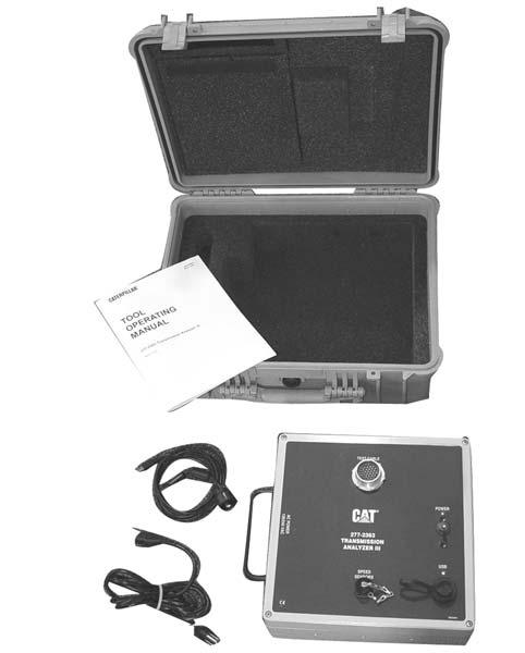
(1) AC Power Cord Connection. (2) Test Cable Connection. (3) Power Indicator Lamp. (4) Power ON/OFF Switch. (5) USB Communication Indicator Lamp. (6) Communication Cable Port. (7) Speed Sensor Connection Port. (8) Handle.
1.AC POWER CORD CONNECTION
External AC power cable is plugged into the connector on the side of the analyzer.
2.TEST CABLE CONNECTION
Various transmission test cables are plugged into this connector.
3.POWER INDICATOR LAMP
Indicates power is on when lit.
4.POWER ON/OFF SWITCH Turns AC power ON and OFF.
5.USB COMMUNICATION INDICATOR LAMP
Flashes when analyzer is connected to PC and two way communication is enabled.
6.COMMUNICATION CABLE PORT
286-0755 USB Cable connects to this port after protective cap is removed.
7.SPEED SENSOR CONNECTION PORT
Speed sensor cable connects to this port after protective cap is removed.
8.HANDLE
Handle for lifting and carrying analyzer.
Before using the 277-2363 Transmission Analyzer III, connect the AC power cord and USB communication cable.
1.Make sure the ON/OFF switch (A) is in the OFF position.
To prevent component damage make sure the transmission analyzer ON/OFF switch is in the OFF position before making any connections.
2.Insert the1U-9485 AC Power Cord connector (B) into the socket below the handle on the unit. Connect the three prong plug to the power supply.

(A)Power ON/OFF Switch. (B) A/C Power Cord Connector.
NOTE: The transmission analyzer can be powered from either a 110 or 240 VAC 50/60 Hz power source. To power the unit with 240 Volt AC, use an appropriate power cable for the plug type used in your region. Plug adapters may be used, but are not recommended.

3.Connect the 286-0755 USB Communication Cable.
a.Un-thread the protective cap from the USB port and insert the USB plug.

b.Secure the USB connection by threading the outer cap onto the fitting.

c.Plug the small end of the communication cable into an open USB port of a dealer-supplied PC.

Software must be installed on the dealer-supplied PC used with the 277-2363 Transmission Analyzer III.
1.Connect the analyzer to the PC with 286-0755 USB Communication Cable and turn the analyzer ON.
2.Insert the Caterpillar Transmission Analyzer III Installation CD into the PC and follow the on screen instructions.
NOTE: If the Setup Wizard screen does not automatically open, select the Transmission Analyzer III icon to open the Setup Wizard screen.

3.From the Transmission Analyzer III Setup Wizard screen select Next

4.From the Confirm Installation screen select Next

5.From theInstallation Complete screen select Close to exit the installation screen.

6.Select the Close ScreenIcon (red X) to close the CD menu screen.

Specific hardware drivers used with the 277-2363 Transmission Analyzer III must be installed on the PC.
1.With the PC operating and the analyzer connected, move the analyzer power switch to the ON position.
2.Insert the Caterpillar Transmission Analyzer III Installation CD in the PC and follow the on screen instructions.
NOTE: If the Found New Hardware wizard screen does not automatically open, do the following:
a.From the PC desktop screen select Start, Settings, Control Panel to open the Control Panel screen.

b.From the Control Panel screen select Add Hardware.

NOTE: If the following Found New Hardware screen opens select No, not this time (A) and Next (B).

3.From the Found New Hardware Wizard screen select Install the Hardware Automatically (Recommended) (A) and Next (B).

4.From the next Found New Hardware screen select Search for the best driver in these locations (A), Search removable media (B), and Next (C).

(A) Search for the Best Driver in These Locations. (B) Search Removable Media. (C) Next.
5.From the Hardware Installation warning screen select Continue Anyway

6.From the next Found New Hardware screen select Finish

1.Connect the transmission analyzer to the dealer-supplied PC using 286-0755 USB Communication Cable.
2.Connect the appropriate analyzer test cable and adapters to the transmission solenoids.
a.Disconnect the machine wiring harness connectors from the solenoids of the transmission.
b.Select the transmission analyzer test cable which has the same connector type as the machine harness that has been disconnected.
c.Insert each 2-pin test cable connector into a solenoid connector.

NOTE: Match the letter and/or number of the test cable to the letter/number of the solenoid being tested. This letter/number is molded into the solenoid valve body.
d.Connect the 31-pin connector of the test cable into the analyzer or the 9U-7498 Extension Cable.
3.Make sure all connections are secure, and move the analyzer power switch to the ON position.
4.With the PC operating and the desktop open, select the CAT TAIII icon to open up the Main Menu screen.

5.The Main Menu screen is comprised of five sections.
A.Analyzer Summary window. Displays model number and software/hardware version information.

B.Machine Summary window. Displays information for the machine transmission being tested once the Machine and Model selection is entered.

(B) Machine Summary Window.
C.System Message window. Displays activity information during the test session.

(C) System Message Window.
D.Options Menu window. Executes Back, Main Menu, Help, and Exit the screen functions. Also opens other menus listing further options and information.

(D) Options Menu Window.
E.Select Product/Get Hardware Version window. Lists machine transmission applications and the Get Hardware Version option.

(E) Select Product/Get Hardware Version Window.
NOTE: All options can be executed by either of two methods.
A.Positioning the cursor and “clicking” on the selection. Transmission Test in this example.
B.Execute the “Hotkey” function by pressing both the alpha key and numeric key on the PC keyboard at the same time (A-1 in this example).

(A) Position Cursor/Click Function. (B) Alpha/Numeric Key Function.
The software program contains additional information for many transmission analyzer functions. This information can be accessed from any screen displaying Help in the menu.
1.From anymenu screen select Help (A) to open the Start Page. Next select Click Here to go to Document Index (B) to open the Document Index window.

(A) Help. (B) Click Here to go to Document Index.
2.Opening the Document Index window displays a selection of subjects that contain operational and test information. Select an item to display that information.

Several specific transmission tests can be performed. Transmission tests require the selection of Product Family, Machine Model and Test Type before performing the actual test.
1.From the Main Menu/Select Product screen select a product family for the transmission to be tested. Articulated Trucks in this example.

2.From the Select Modelscreen select a machine model for the transmission to be tested. 735-24V in this example.

3.From the Test Type Menuscreen select a specific test type. Transmission Test in this example.

NOTE: When testing Challenger Tractors, there are more choices available on this screen. These choices allow you to perform certain functions, such as initializing two solenoids at the same time.
Test information and procedures for many transmission types are available with 277-2363 Transmission Analyzer III software.
1.The Special Instruction title (if available) for test procedures that apply to a selected transmission are listed in the Machine Summary window (A).

(A) Machine Summary Window.
2.Select Show Procedure (B) from the Options Menu to open the Special Instruction (C) publication file.

(B) Show Procedure. (C) Special Instruction.
This function shifts the transmission through selected gears.
This test requires the transmission analyzer to be connected and turned on before opening the Transmission Test screen on the PC.
To avoid damage to the transmission and/or personal injury, it is the responsibility of the user to obtain and read any operating instructions for the transmission to be tested. Always verify you have the most up to date information before testing the transmission.
Do not use the 277-2363 Transmission Analyzer III in the transmission test mode with the transmission in the machine. Using the analyzer to shift the transmission while it is in the machine can be harmful to the transmission and dangerous for the operator. The transmission must be mounted on a hydraulic test stand for the transmission test mode.
1.From the Test Type Menu screen select Transmission Test and follow the test procedure to perform the transmission shift test.
2.Gear changes can be made using “Hotkeys” (A) or by clicking on the desired gear in either the Select Gear (B) or Select/Actual (C) window.

(A) HotKeys. (B) Select Gear. (C) Select/Actual.
Transmission Types :
• Sequential Shift Transmission
Gears listed in order with the highest forward gear listed first.
Example: 1F to5F shift.
1F → 2F
2F → 3F
3F → 4F
4F → 5F
The transmission must be in Neutral to exit the screen.
• Standard Transmission
Gears not listed in any particular order. Gear changes executed directly from any gear to any other gear. Example: 1F to5F is one shift.
• ICM Transmission
A different type transmission, but controlled the same for this transmission test screen.
NOTE: For additional information on this test procedure, refer to the Help Screens section in this manual.
:
NOTE: Special cables may be needed to connect speed sensors to the 277-2363 Transmission Analyzer III
•The two speed displays are updated every 500 milliseconds and are active when the Transmission Test screen is displayed.
•The values are shown as a raw frequency in HZ. If a sensor is not connected, the speed output will read zero.
:
• Upshift / Downshift
Only shown for sequential transmissions. Upshifts or downshifts by one gear at a time.
• Special Tests
Any special tests available in the database are listed next. The special tests can only be run while in the Transmission Test screen. Once a special test is started, it must be ended to change to another gear or to exit.
• Single Solenoid Control
If a solenoid is listed in the database as controllable, it will be listed next. The solenoid can be enabled or disabled for shift patterns.
• All Gears
Change from one gear to the next by using “Hotkeys” or by selecting the box with the gear listed in either the Select Gear or Select / Actual window.
NOTICE
Always be aware of how many neutrals and reverse speeds are in the transmission being tested. Shifting errors can occur if the wrong transmission shift pattern is selected.
3.From the Options Menu select Back to return to the Test Type Menu screen.

NOTE: The transmission must be in neutral (N) in order to exit the Transmission Test screen.
This function tests the operation of shift levers on non-autoshift transmissions. This test requires the transmission analyzer to be connected and turned on before opening the Shift Lever Test screen on the PC.
NOTE: With the engine off and the transmission not rotating, the Shift Lever Test can be performed with the transmission mounted in or out of the machine.
1.From the Test Type Menuscreen select Shift Lever Test and follow the test procedure.

2.The Shift Lever Test screen displays the current shift lever position of the transmission. The display is live upon entering the Shift Lever Test screen.

NOTE: For additional information on this test procedure, refer to the Help Screens section in this manual.
This function checks the condition of solenoids. The test will turn solenoids ON and OFF individually or sequentially.
NOTE: The Solenoid Test does not measure electrical resistance of the solenoid. Use the Harness Test to measure electrical resistance.
This test requires the transmission analyzer to be connected and turned on before opening the Solenoid Test screen on the PC.
The transmission should not be rotating while using the “Solenoid Test” screen. Energizing a solenoid while the transmission is rotating can be harmful to the transmission and dangerous for the operator.
NOTE: With the engine off and the transmission not rotating, the Solenoid Test can be performed with the transmission mounted in or out of the machine.
1.From the Test Type Menuscreen select Solenoid Test

2.Make sure the transmission is not rotating. Select OK in the warning window and follow the test procedure to perform the transmission solenoid test.

NOTE: For additional information on this test procedure, refer to the Help Screens section in this manual.
3.When a solenoid is selected it will be first displayed in YELLOW, then in GREEN if working properly, or RED if there is a fault.

• Cycle All
This optionstarts with Solenoid #1 and energizes each solenoid, in sequence for three seconds each. This cycle will continue to repeat until the Stop option is selected.
• Stop
This option stops the Cycle All option and turns OFF the currently selected solenoid. This option can also be used to turn OFF any individually selected solenoid.
• All Solenoids
This option selects an individual solenoid to turn ON. The selected solenoid will turn ON and be displayed in GREEN or RED until the Stop option is selected or another solenoid is selected.
The 277-2363 Transmission Analyzer III has the capability of testing electronically actuated pumps installed on the hydraulic test bench. The analyzer controls these pumps by energizing the actuating solenoids inside the pump. Caterpillar has developed test procedures for these pumps using the 277-2363 Transmission Analyzer III. Caterpillar is continuing to develop new test procedures and is releasing them on Cat Service Information System (SIS). If you have a copy of NETG5048 Annual Software Subscription Bench Testing Hydraulic Components that does not have the test procedure for electronically actuated pumps; check SIS for special instructions on the pump.
This function checks the integrity of the wiring harness, when connected. The Harness Test executes multiple checks for each solenoid connection.
This test requires the transmission analyzer to be connected and turned on before opening the Harness Test screen on the PC.
1.From theTest Type Menu screen select Harness Test and follow the test procedure to perform the transmission harness test.

NOTE: For additional information on this test procedure, refer to the Help Screens section in this manual.
2.Perform the harness test to check the following.
•Short to ground.
•Short to power.
•Short from high to low of solenoid.
•Resistance of each solenoid.
Harness Test Menu Options :
• Print (A) Prints results to the default printer, if available
• Retest (B) Executes the harness test.

(A) Print. (B) Retest.
This function allows setup of additional operational default settings. These default settings can be saved for future sessions.
1.From the Main Menu screen select Options

2.From the Action Menu screen select Preferences , and follow the procedures to customize analyzer parameters.

NOTE: For additional information on this procedure, refer to the Help Screens section in this manual.
3.Customizable parameters screen.
A Procedure File Locations
Setup file locations for procedure files. The procedure files are displayed.
B Calibration File Locations
Setup file locations for calibration files. The calibration files are generated by the ECPC calibration screen.

(A) Procedure File Locations. (B) Calibration File Locations.
C Enable ECPC Calibration
This feature shows/hides menu options for calibration.
D Raw USB Transmit Window
This feature is reserved for advanced users only.

(C) Enable ECPC Calibration. (D) Raw USB Transmit Window.
E. Raw USB Monitor Window
This feature is reserved for advanced users only.
F. Tracing
• Show Debug Messages in Diagnostic Window
This feature is reserved for advanced users only.
• Log Trace Messages to File
This feature logs activity to a file. Current activity can be printed from this file.

Raw USB Monitor Window. (F) Tracing.
G Log File
Options allowed for log file are to Append to existing or to Overwrite to existing log files.

(G) Log File.
The function will be used for Electronic Clutch Pressure Control (ECPC) calibration, when it becomes available.
This procedure can only be selected if it is available for a particular model of transmission.
1.From the Options Menu screen select Help (A) and then select Click Here to go to Document Index (B) to open the Document Index.
(A) Help. (B) Click Here to go to Document Index.
2.Select ECPC Calibration on the Documentation Index screen.

3.If calibration data is found when the ECPC test option is selected, three menu choices are displayed.
• Recalibrate (make new data)
This option deletes the previous calibration data.
• Use Existing Calibration Data
This option uses the existing calibration data created within the current session.
• Use the Default Calibration Data
This option uses data that exists in the calibration file with no updates.
4.After data is entered, selecting BACK saves the solenoid setup data to the ECPC solenoid data file.
•In the Solenoid Entry screen the Action menu displays Hold Current and Engagement Current for each solenoid.
•Only the New Value (mAmps) field can be modified. When Edit Mode is activated the Options Menu item text changes from START to STOP and the background colorof the New Value (mAmps) field changes to RED.
•Two fields can be selected (Hold Current or Engagement Current) to alter the value in increments of 1% of the difference of the MAX and MIN values.
•Previous values that exist in the ECPC calibration file can be restored by using the Restore Default Values option.
NOTE: If no calibration data was found, new calibration data can be setup for all solenoids. Data must be setup for all solenoids at the same time. No provision to edit individual solenoid values is available.
To keep the transmission analyzer up-to-date, there is a NETG5048 Software Subscription available.
1.Connect the 286-0755Communications Cable between the USB port on the computer and the USB port on the analyzer.
2.Turn ON the PC and transmission analyzer.
3.Insert the disk in the computer disk drive.
4.FromtheMain Menu screen select Options .
5.From the Action Menu screen select Update Database , and Select New Database

6.Choose the new database file from menu window (A) and then select Update Now (B)

(A) Menu Window. (B) Update Now.
NOTE: For additional information on this procedure, refer to the Help Screens section in this manual.
7.The following events will occur after selecting Update Now
a.The current working database is copied and saved (archived) in the system-defined database path with a date and time stamp in the file name.
b.The current database is deleted.
c.The new selected database is copied to the working system with the active file name known by the transmission analyzer software system as the current live data.
8.The user is allowed to switch between versions of the database. Each time a new database is selected, Steps 6a, 6b, and 6c are preformed.
This function is used to download new firmware from the PC to the transmission analyzer unit.
1.Connect the 286-0755Communications Cable between the USB port on the computer and the USB port on the analyzer.
2.Turn ON the PC and transmission analyzer.
3.FromtheMain Menu screen select Options
4.From the Action Menuscreen select Download Firmware, and Select File

5.Select the file to be downloaded and select Download Now to start the actual download process.
NOTE: For additional information on this procedure, refer to the Help Screens section in this manual.
If the 277-2363 Transmission Analyzer III does not operate properly, perform the Self Test procedure. If the analyzer is faulty, contact Dealer Service Tools before returning the unit for repair. Units less than one year old will be repaired under warranty (except for abuse). The cost of out-of-warranty repair will be charged to the owner.
When returning units to Caterpillar’s Tool Repair Service, be sure to enclose a letter describing the problem and include the date of purchase. If the tool is out-of-warranty, include a Purchase Order Number with the shipment.
For additional product support questions concerning this tool, contact the Caterpillar Dealer Service Tools Hotline at:
U.S.A.: 1-800-542-8665
Illinois: 1-800-541-8665
Canada: 1-800-523-8665
World: 1-309-675-6277
Fax: 1-309-494-1355
dealerservicetool_hotline@cat.com
1.With the PC and transmission analyzer connected and turned on, select Options from the Main Menu screen
2.From the Action Menu screen, select Self Test .

3.Follow the on-screen instructions to complete the self test.

4.After the test results are displayed, the Action Menu options are Print (A) test results or Retest (B)
(A) Print. (B) Retest.
NOTE: For additional information on this test procedure, refer to the Help Screens section in this manual.
5.If the Self Test procedure indicates a possible problem, contact Dealer Service Tools.
The 277-2363 Transmission Analyzer III software is supported through Caterpillar Dealer Service Tools support channels.
1.From the Main Menuscreen select Help (A). From the Start Page window select Click Here to go to Document Index (B).
(A) Help. (B) Click Here to go to Document Index.
2.From the Document Indexscreen select Support to open the support contact information page.

1-800-541-8665
1-800-523-8665
1-309-675-6277
To avoid damage and/or personal injury, keep all liquids away from the transmission analyzer and dealer supplied PC. Follow all electrical safety procedures to prevent injury or death by electrical hazards.
1.Keep the analyzer and related components clean and dry. Keep all connections covered when not in use.
2.Wipe the analyzer and related components with a dry clean cloth, as needed.
2.Store the analyzer and related components in the protective case, in a clean, dry, temperature controlled environment.
277-2363 Transmission Analyzer III Group

277-2363 Transmission Analyzer III Group
ItemPart No.Description
1277-2363Transmission Analyzer III
21U-9485AC Power Cable
Connects conventional utility power to the Transmission Analyzer III. The unit automatically operates on both 120 or 240 Volt 50/60 Hz systems. The 1U-9485 AC Power Cable is configured for 120 Volt AC at 50/60 Hz. Refer to Safety Section, Power and PC Connections, for 240 VAC operation.
3286-0755Communications Cable
USB communications cable connects analyzer to a computer USB port.
4NEHS0996Tool Operating Manual
5—Carry Case
Hinged hard shell case with foam pocket storage for components.

Optional Items for 277-2363 Transmission Analyzer III Group
ItemPart NoDescription
11U-9479Adapter Cables [155 mm (6.0 in) long]
21U-9480Adapter Cables [155 mm (6.0 in) long]
Used to change the connectors of 9U-7496 and 9U-7497 Test Cables from pins to sockets. Cables are used mainly when testing the shift lever from the transmission solenoid connections. These cables may also be required when 9U-7496 and the 9U-7497 Test Cables are connected to certain transmissions.
36V-9412Switch Test Adapter Cable
Used for connecting the transmission analyzer to the connector on the shift console of machines with ICM (Individual Clutch Modulation) transmissions. Used with the 120-9288 Harness Assembly for transmissions with Hall Effect transmission switches.
41U-9483Test Cable [152 cm (60.0 in) long]
Used for testing the Challenger 35, 45, and 55 transmissions.
51U-9482Test Cable [152 cm (60.0 in) long]
Used for testing the ICM (Individual Clutch Modulation) transmissions. Connects the transmission analyzer to the gear position switch, Upshift, Downshift, and Lockup solenoids of the ICM transmission.
69U-7495Test Cable [152 cm (60.0 in) long]
Connects standard bulkhead connector on most Wheel Loader Transmissions to the transmission analyzer.
Optional Items for 277-2363 Transmission Analyzer III Group (continued)
9U-74961
—9U-74971
—9U-74981
Test Cable {152 cm (60 in) long}
Two-pin Deutsche connectors connect directly to solenoids of Caterpillar transmissions with Deutsche connectors.
Test Cable {152 cm (60 in) long}
Two-pin Sureseal connectors connect directly to solenoids of Caterpillar transmissions with Sureseal connectors.
Extension Cable [6 m (20 ft) long]
Used between transmission analyzer and appropriate test cable.
—4C-59741 Adapter
May be needed for some transmissions.
—232-10651 Sureseal to Deutsche Adapter Required for some newer ICM Transmissions.
—241-48791 3-pin Deutsche to 2-pin Deutsche Adapter Required for some transmissions.
—256-76231 17 Pin to 14 Pin Adapter Required for T Series Dozer
—300-49931 17 Pin to 14 Pin Adapter
Required for Some R and T Series Dozer
—307-35421 17 Pin to 14 Pin Adapter
Required for D11 R Series Dozer
Serial # 7T2, 9TR, 9XR, and AAF
1 Not Shown.
For information on service tools or shop supplies, contact Dealer Service Tools on:
Dealer Service Tools
501 S. W. Jefferson
Peoria, ILU.S.A. 61630-2125
U.S.A.: 1-800-542-8665
Illinois: 1-800-541-8665
Canada: 1-800-523-8665
World: 1-309-675-6277
Fax: 1-309-494-1355
dealerservicetool_hotline@cat.com