Description
Wire Color
Power Circuits
Component Identifiers (CID¹) Module Identifier (MID²) Engine Control (MID No. 036)
Description
Control Circuits (Continued)
101
RD
Battery (+)
795
YL
Quick Coupler Relay
102
BU
Head Lamp
797
PU
Platform Mode Switch
103
RD
Head Lamp
798
GN
Mode Switch
CID
105
BR
Key Switch
799
WH
PHS Valves +10V
0041
ECM (Electronic Control Module) 8 Volt DC Supply
108
RD
Battery (+) to Product Link
852
GN
Cont Flow
109
RD
Alt Output (+) Term
854
PK
Boom Angle Switch
0091
Throttle Position Sensor
111
RD
Machine Control Battery (+)
856
GN
Trigger Switch Parity
0100
Engine Oil Pressure Sensor
112
PU
Main Power Relay Output
863
BU
Cab/Platform Indicator Switch
0102
Boost Pressure Sensor
114
RD
Warning Horn (Forward)
867
PU
PHS Joystick Grip Control
0105
Inlet Manifold Temperature Sensor
116
BR
Frame Level/Tow
869
PU
Cont Flow Switch
117
RD
Lift Pump Battery (+)
870
OR
Frame Interlock Relay
0110
Engine Coolant Temperature Sensor
118
GY
Front Wiper Motor
874
GY
LSI Sensor
0174
Fuel Temperature Sensor
119
PK
Wiper Motors Switch Power
892
BR
CAT Data Link (+)
0247
SAE J1939 Data Link
121
YL
Accessory Socket
893
GN
CAT Data Link (-)
0253
122
BU
Fuel Injector Relay
900
PU
Transmission Shift Solenoid
123
WH
Cold Start Relay
901
WH
Transmission Shift Solenoid
124
GN
AC Blower (Low)
902
BR
Transmission Shift Solenoid
125
OR
RH Tail Lamp
911
YL
Steering Mode Switch
127
OR
Boom Floods
913
BU
Front Wiper Switch
128
PK
AC Blower (High)
944
OR
130
GN
Cab Floods 2
945
BR
131
BR
Cab Floods 1
958
133
OR
PHS
135
BU
136
GN
141 144
Component Location Schematic Location
Machine Location
ACCELERATOR
G-6
1
ALARM - BACKUP
C-18
Component
Schematic Location
Machine Location
SENSOR - FRONT AXLE CENTER
F-2
11
2
SENSOR - INTAKE MANIFOLD PRESSURE
D-8
E
Component
Connector Location Connector Number
ALARM - MONITOR
I-5
3
SENSOR - INTAKE MANIFOLD TEMP
D-8
E
ALARM - PLATFORM
I-2
A
SENSOR - LEVER BOOM EXTEND/RETRACT
K-3
G
ALTERNATOR
C-6
4
SENSOR - LEVER BOOM RAISE/LOWER
K-3
G
ANTENNA - MSS TIRIS
G-6
C
SENSOR - LEVER PLATFORM ROTATE
L-3
G
ANTENNA - RADIO
G-6
5
SENSOR - LSI STRAIN
D-17
ARC SUPPRESSOR - CIRCLE
K-4
6
SENSOR - MASTER
L-2
ARC SUPPRESSOR - CRAB
L-4
6
SENSOR - OIL PRESSURE
D-8
ARC SUPPRESSOR - LH STAB LOWER
G-1
7
SENSOR - REAR AXLE CENTER
B-17
40
ARC SUPPRESSOR - LH STAB RAISE
G-1
7
SENSOR - SHIFT RAIL 1
D-11
F
ARC SUPPRESSOR - RH STAB LOWER
F-1
7
SENSOR - SHIFT RAIL 2
C-11
F
ARC SUPPRESSOR - RH STAB RAISE
G-1
7
SENSOR - SHIFT RAIL 3
C-11
F
Personality Module
BATTERY 1
A-6
8
SENSOR - SLAVE
M-2
G
CONN 8
0262
5 Volt Sensor Power Supply
BATTERY 2
A-6
8
SENSOR - TC OIL TEMPERATURE
C-11
F
0266
Crank Without Injection Input
BEACON
M-17
9
SENSOR - TC SPEED
E-10
0320
Speed/Timing Sensor
BLOCK - FUSE
F-16
D
SENSOR - VLPM
E-8
0342
Secondary Engine Speed Sensor
BLOCK - FUSE
I-16
D
SENSOR - XMSN INT SPEED 1
E-10
F
Secondary Throttle Position Sensor
G-16
D
SENSOR - XMSN OIL TEMPERATURE
D-10
F
CDL (-)
0774
BLOCK - RELAY BLOCK - RELAY
J-16
D
SENSOR - XMSN OUT SPEED
D-10
F
CDL (+)
1627
Fuel Pump Relay
BREAKER - ALTERNATOR
B-7
10
SOCKET - ACCESSORY
L-15
29
YL
Solenoid QC
C-7
10
SOCKET - ADAPTER
M-17
A
WH
Arc Suppressor QC
Machine Security System Module
BREAKER - MAIN
959
1639
B-6
10
SOLENOID - 1 REVERSE
A-11
F
975
WH
Solenoid Return
Fuel Injection Pump
BREAKER - STARTER
Radio Power
1684
Auxiliary Circuit
985
GY
Crab Steer Relay
1743
Engine Operation Mode Selector Switch
BUS BAR
D-5
E
SOLENOID - 2 FORWARD
A-11
F
PK
Seat
986
OR
Circle Solenoid
1894
Cruise Control Disengage Switch
COIL - FERRITE
D-2
11
SOLENOID - A/C COMPRESSOR
D-6
E
GN
Beacon
987
WH
Diverter Solenoid
1895
Cruise Control Speed Toggle Switch
CONTROL - ECM (ACCESS PLATFORM)
M-1
G
SOLENOID - AUX DIV
H-1
41
CONTROL - ENGINE
C-9
E
SOLENOID - CIRCLE
L-4
6
CONTROL - JOYSTICK
G-5
A
SOLENOID - CRAB
L-4
6
CONTROL - MACHINE
E-3
12
SOLENOID - DIFFERENTIAL LOCK
D-10
CONTROL - MACHINE SECURITY SYSTEM
F-1
11
SOLENOID - FRAME LEVEL 1
D-2
CONTROL - PHS VALVE SSV4
D-17
13
SOLENOID - FRAME LEVEL 2
C-1
42
CONTROL - PRODUCT LINK
H-5
14
SOLENOID - IMPLEMENT DISABLE
B-17
13
147
PU
Auxiliary Div Power
990
GN
Diverter Solenoid
150
RD
Engine ECM Battery (+)
991
WH
Shift Rail Sensor
157
YL
Turn Indicator Switch Power
993
BR
Accelerator
161
RD
Hazard Indicator
994
GY
Oil Pressure Sensor
165
YL
Differential Lock Foot Switch
995
BU
Coolant Temperature Sensor
167
OR
Access Platform ECM
Component
Machine Control (MID No. 039)
CID
Component
31200311 December 15, 2006
Schematic Location
Machine Location
M-18
A
CONN 1 CONN 2
L-18
A
39
CONN 3
D-18
50
G
CONN 4
C-17
52
E
CONN 5
E-17
53
CONN 6
B-16
52
CONN 7
D-15
52
D-15
52
CONN 9
L-15
29
F
CONN 10
L-14
29
F
CONN 11
D-13
53
CONN 12
E-13
53
CONN 13
F-13
53
CONN 14
G-13
53
CONN 15
M-13
54
CONN 16
M-12
A
CONN 17
M-12
A
CONN 18
D-11
F
CONN 19
H-10
29
F
CONN 20
H-10
29
42
CONN 21
E-9
55
CONN 22
L-8
48
0041
ECM (Electronic Control Module) 8 Volt DC Supply
0070
Parking Brake Switch
CONTROL - SHIFTER
K-8
A
SOLENOID - LEFT STAB LOWER
G-1
7
CONN 23
L-8
48
DISPLAY CLUSTER
J-5
C
SOLENOID - LEFT STAB RAISE
H-1
7
FLASHER
L-13
15
SOLENOID - LOAD SENSE CONTROL
A-5
36
CONN 24
L-8
48
FLOOD - BOOM LH
H-2
16
SOLENOID - RIGHT STAB LOWER
G-1
7
CONN 25
C-7
E
FLOOD - BOOM RH
H-2
17
SOLENOID - RIGHT STAB RAISE
G-1
7
CONN 26
D-6
56
FLOOD - FRONT LH CAB
M-1
18
SOLENOID - SPEED 1
A-10
F
CONN 27
D-6
E
FLOOD - FRONT RH CAB
I-1
19
SOLENOID - SPEED 2
A-10
F
CONN 28
B-5
57
CONN 29
I-5
A
997
OR
Not Used
Ground Circuits
999
WH
Fuel Injector Pump
A700
OR
Accelerator
0096
Fuel Level Sensor
200
BK
Main Chassis
205
BK
Chassis
A701
GY
Not Used
0110
Engine Coolant Temperature Sensor
229
BK
Engine
A702
PU
Not Used
A278
BK
Fuel Pump Return
A703
BR
Not Used
0177
Transmission Oil Temperature Sensor
A704
GN
Not Used
0262
5 Volt Sensor Power Supply
304
WH
Starter Relay No. 1 Output
A705
BU
Not Used
0271
Action Alarm
306
GN
Starter Relay Coil
A706
GY
Not Used
0368
Transmission Auto/Manual Switch
FLOOD - REAR LH CAB
K-16
20
SOLENOID - SPEED 3
A-10
F
307
OR
Key Switch
A707
PU
Not Used
0444
Starter Motor Relay
FLOOD - REAR RH CAB
G-17
21
SOLENOID - SPEED 4
A-10
F
308
YL
Main Power Relay Coil
A708
BR
Not Used
E
SOLENOID - SPEED 5
A-10
F
CONN 30
M-4
58
Cold Start Relay
A709
OR
Not Used
Trigger Switch (Aux.) of Joystick Control
C-6
YL
0489
FUSE - FUEL PUMP
317
A
SOLENOID - SYNC MOD
A-11
F
BR
Backup Alarm
A710
GY
Air Restriction Indicator
Implement Lockout Switch
H-5
321
0490
GPS VHF
E
SOLENOID -QC
H-1
44
58
322
GY
Warning Horn (Forward)
A711
PU
Not Used
Engine Control Module
A-7
M-4
0590
HEATER - COLD START
CONN 31
14
SPEAKER - LH
L-16
A
G-3
59
323
WH
Fuel Pump Power
A712
BR
Not Used
Neutralizer Switch
J-5
CONN 32
0629
HORN LAMP - ACTION
I-1
G
SPEAKER - RH
H-17
A
CONN 33
K-3
60
324
BU
Differential Lock Solenoid
A746
PK
Not Used
I-17
A
SUPPRESSOR - BACKLIGHT SIGNAL
H-5
A
PK
Fuel Pump Relay Cut-out
C712
BR
Right Stabilizer Down Pressure Switch
Transmission Shift Lever
LAMP - DOME
325
0668
M-4
22
SUPPRESSOR - FRAME LEVEL 1
D-2
35
L-3
G
329
YL
Fuel Pump to Switch
C713
GY
Left Stabilizer Down Pressure Switch
Transmission Gear Lever Selector Sensor (Switch)
LAMP - HEAD LH
CONN 34
0702
LAMP - HEAD RH
C-1
26
SUPPRESSOR - FRAME LEVEL 2
C-2
35
13
BU
Shutdown Switch to Shutdown Control
C743
PK
Parking Brake Switch Disengaged
Rear Steering Manual Switch
H-2
332
0750
CONN 35
24
SUPPRESSOR - FRAME LEVEL DUMP POS 1
D-1
35
CONN 36
F-2
35
BU
Start Relay No. 1 Resistor to Diagnostic
C744
PU
Parking Brake Switch Engaged
Gauge Cluster #1
E-18
352
0811
LAMP - REG PLATE 1
375
BR
Cold Start Relay to Engine ECM
C903
BU
Stabilizer Relay 1
0826
Torque Converter Oil Temperature Sensor
LAMP - REG PLATE 2
D-18
24
SUPPRESSOR - FRAME LEVEL DUMP POS 2
C-1
35
CONN 37
C-2
61
A309
GY
Fuel Lift Pump
C905
OR
Stabilizer Relay 2
LAMP - STOP/TAIL/TURN/REV LH
E-18
23
SWITCH - A/C HIGH PRESSURE
E-6
E
Transmission Temperature Switch (V+)
C917
YL
RH Stabilizer Switch
LAMP - STOP/TAIL/TURN/REV RH
B-18
25
SWITCH - AIR RESTRICTION INDICATOR
E-7
E
62
BU
Position Sensor - (Fwd./Back Lever) of Joystick Control
E-1
A310
1127
CONN 38
C919
PU
LH Stabilizer Switch
1128
Position Sensor - (Left/Right) of Joystick Control
LAMP - STOP/TURN/TAIL/FOG LH
F-18
23
SWITCH - BEACON
J-8
C
LAMP - STOP/TURN/TAIL/FOG RH
A-18
25
SWITCH - BLOWER ON
E-6
E B
Basic Machine Circuits
Monitoring Circuits 403
GN
Alternator Terminal
C967
BU
Intake Manifold Temperature Sensor
1187
Continuous Flow Switch
428
OR
Opr Mon Transmission Oil Temperature
C993
WH
Shift Rail Sensor
1189
Position Sensor - (Aux. Hyd.) R Thumb of Joystick Control
443
YL
Power Train Temperature Gauge
E528
PU
HVAC Blower
1251
Alternator R-Terminal Signal
447
PK
Fuel Level Gauge
E529
YL
HVAC Blower
A487
PU
Opr Mon Fault Alarm No. 2
E798
PK
Not Used
1326
ECM Location Code
C444
YL
Alternator Indicator Lamp
E900
WH
Transmission Out Speed Sensor
1401
Transmission Solenoid 1
MOTOR - FRONT WIPER
E450
GN
Oil Filter Bypass Switch
E901
GN
Transmission Out Speed Sensor
1402
Transmission Solenoid 2
MOTOR - FUEL LIFT PUMP
E902
PU
Transmission Intermediate Speed Sensor
1403
Transmission Solenoid 3
1404
Transmission Solenoid 4
1405
Transmission Solenoid 5
1406
Transmission Solenoid 6 Transmission Solenoid 7
Accessory Circuits 500
BR
Wiper - Front (Park)
E903
YL
Transmission Intermediate Speed Sensor
501
GN
Wiper - Front (Low)
E908
BR
Sensor
502
OR
Wiper - Front (Hi)
E909
WH
Sensor
503
BR
Wiper - Rear (Park)
E960
OR
Engine Shutdown Switch
504
YL
Wiper - Rear (Low)
E965
BU
Engine Speed Sensor
1407
506
PU
Washer - Front
E966
YL
Engine Speed Sensor
1410
Transmission Solenoid 10
507
WH
Washer - Rear
F700
BU
Not Used
508
PU
Speaker - Left
F701
BR
Not Used
1529
Quick Coupler Switch
509
WH
Speaker - Left (Common)
F702
GN
Accelerator Signal
1530
Quick Coupler Solenoid
511
BR
Speaker - Right
F703
GY
Not Used
1603
Data Link
512
GN
Speaker - Right (Common)
F705
PK
Not Used
1658
Position Sensor - Left Thumb Lever of Joystick Control
513
OR
AC Compressor/Refrigerant Pressure Switch
F706
PU
Not Used
515
GY
Blower Motor (High)
F707
WH
Not Used
1740
Crab Steering Solenoid
516
GN
Blower Motor (Medium)
F708
YL
Not Used
1741
Circle Steering Solenoid
517
BU
Blower Motor (Low)
F709
BU
Not Used
1763
Operator Station Selector Switch
518
OR
Hazard Flasher to Switch
F710
BR
Lift Pump
1788
Right Stabilizer Operator Switch
521
YL
AC Switch to Refrigerant Switch
F711
GN
CAN Link +
1789
Left Stabilizer Operator Switch
522
WH
AC Clutch to Thermostat Switch
F712
GY
CAN Link -
523
BR
Roof Wiper
F714
PK
Not Used
1820
Auxiliary Implement Diverter Relay
524
BU
Roof Wiper
F715
PU
Not Used
1823
529
WH
Roof Washer
F716
WH
Not Used
536
WH
Hazard Switch to Turn Switch
F717
YL
A515
BR
Blower Motor No.2 (High)
F718
A516
PK
Blower Motor No.2 (Medium)
F719
C547
OR
Blower Motor No. 2 (Medium - Low)
E554
PK
SWITCH - BOOM FLOOD
F-9
G
SWITCH - CAB FLOOD
F-8
B
MOTOR - BLOWER
H-11
28
SWITCH - CAB PLATFORM SELECT
F-10
B
MOTOR - FRONT WASHER
K-13
29
SWITCH - CONT FLOW
H-7
C
L-4
14
SWITCH - DEADMAN
J-3
G
A-7
E
SWITCH - DIFFERENTIAL LOCK FOOT
L-7
45
MOTOR - REAR WASHER
K-13
28
SWITCH - DIMMER
J-7
C
MOTOR - REAR WIPER
I-17
30
SWITCH - DISCONNECT
A-7
E
MOTOR - ROOF WASHER
K-13
28
SWITCH - ENGINE START
J-1
G
J-17
31
SWITCH - ENGINE STOP
J-3
G
G-11
28
SWITCH - FOG LAMP
H-8
C
MOTOR - STARTER
B-6
32
SWITCH - FRAME LEVELING
H-6
C
PUMP - FUEL INJECTOR
E-8
E
SWITCH - FRONT WASHER
F-7
B
RELAY - AUX DIV GROUND
G-15
D
SWITCH - FRONT WIPER
F-7
B
RELAY - AUX DIV POWER
G-15
D
SWITCH - HAZARD
J-6
C
RELAY - BLOWER HIGH
I-11
15
SWITCH - HEAD/SIDE LAMP
J-7
C
RELAY - BLOWER MEDIUM HIGH
I-10
15
SWITCH - HEAT/AC
F-6
B
RELAY - CIRCLE STEER
J-15
D
SWITCH - HORN
K-5
C
RELAY - COLD START
A-7
10
SWITCH - HVAC BLOWER
F-6
B
RELAY - CRAB STEER
J-16
D
SWITCH - IMPLEMENT DISABLE
F-10
B
RELAY - FRAME LEVEL INTERLOCK
G-16
D
SWITCH - KEY START
G-6
C
RELAY - FUEL PUMP
B-6
10
SWITCH - LH STAB
H-6
C
RELAY - LIFT PUMP
G-15
D
SWITCH - LH STAB PRESSURE
H-1
46
RELAY - MAIN POWER
G-13
33
SWITCH - MAN VSC
K-8
A
RELAY - QUICK COUPLER POWER
J-15
D
SWITCH - OIL FILTER BYPASS
D-7
E
Position Sensor - Shift Rail No.1
RELAY - REVERSE LAMPS
J-15
D
SWITCH - PARK BRAKE
M-13
A
1824
Position Sensor - Shift Rail No.2
RELAY - STABILIZER 1
J-16
D
SWITCH - PLATFORM MODE
J-2
G
Not Used
1825
Position Sensor - Shift Rail No.3
RELAY - STABILIZER 2
G-16
D
SWITCH - QUICK COUPLER
K-7
C
BU
Not Used
1826
Longitudinal Stability Indicator Sensor
RELAY - START
B-5
10
SWITCH - REAR WIPER
F-8
B
BR
Not Used
1827
Longitudinal Stability System
RELAY- QUICK COUPLER GROUND
J-15
D
SWITCH - REV FAN
K-6
A
RESISTOR - ALTERNATOR
C-7
4
SWITCH - RH STAB
H-7
C
1828
Boon Angle Switch
RESISTOR - TERMINATING
I-5
C
SWITCH - RH STAB PRESSURE
H-1
47
1829
Boom Position Status
RESISTOR - TERMINATING RES 1A
D-17
34
SWITCH - ROOF WIPER
F-7
B
RESISTOR - TERMINATING RES 2B
F-2
35
SWITCH - SERVICE BRAKE PRESSURE
M-9
1
GN
Not Used
GY
Not Used
Lighting Circuits
F722
OR
Not Used
603
PK
Rotary Beacon
F727
BU
Not Used
1830
Boom Telescope Position Status
604
OR
Stop Lamp
F729
GN
Air Restriction Indicator
605
YL
Turn Lamp - Left
F770
BR
Fuel Injector Pump
1831
Rear Axle Lock Solenoid Switch
606
GY
Turn Lamp - Right
F799
BU
Frame Level Dump Position 1/2
1832
Right Stabilizer Pressure Sensor
608
GN
Flood Lamp - Rear
F846
PU
Machine Security Red LED Signal
1833
Left Stabilizer Pressure Sensor
610
OR
Head Lamp - Basic
G757
OR
Transmission Neutralizer Switch 2
1834
Ignition Key Switch
611
PU
Head Lamp - Hi
G848
GN
Machine Security Green LED Signal
1845
612
GY
Backup Lamp
G962
OR
Implement Disable Solenoid
614
PU
Park/Tail/Dash Lamp
G970
BU
Flow Control Valve
615
YL
Cab Flood Lamp
H750
BR
Front Axle Center
616
BU
Bucket/Boom Flood Lamps
H751
OR
Rear Axle Align Switch
617
BR
Tail/Position Lamp - Left (Road Pkg) Width
H764
GY
Circle Steer Relay
618
YL
Tail/Position Lamp - Right (Road Pkg) Width
H765
WH
Crab Steer Relay
619
GN
Head Lamp (Low)
H802
GY
Proportional Driver Return (5-8)
627
YL
Fog Lamp
J755
BU
Left Frame Level Solenoid Return
649
YL
Light Switch to Park/Tail Lamp Breaker
J756
BR
676
PU
Auxiliary Active Lamp
J757
PU
750
GN
751
GN
Transmission Shift Solenoid - Forward
752
YL
Transmission Shift Solenoid - Reverse
753
GY
Cab Platform Select Switch
754
BU
755
OR
756 757
A-4
36
SWITCH - STEER MODE SELECT
K-6
C
SENDER - FUEL
E-15
37
SWITCH - STOP LAMP
L-8
48
SENSOR - BOOM LOWERED
C-18
2
SWITCH - TOW HITCH
F-9
B
SENSOR - BOOM RETRACTED
M-2
38
SWITCH - TURN SIGNAL
G-8
A
SENSOR - COOLANT TEMPERATURE
D-8
E
SWITCH - XMSN NEUTRAL DISABLE
K-7
C
Programmable Hydraulic System Pilot Module #1
SENSOR - ENGINE SPEED
D-8
E
THERMOSTAT
H-10
28
1846
Programmable Hydraulic System Pilot Module #2
Machine locations are repeated for components located close together.
1847
Programmable Hydraulic System Pilot Module #3
A = Located inside of cab.
Access Platform Control (MID No. 082)
CID
Component
0271
Action Alarm
Right Frame Level Solenoid Return
0324
Warning Lamp (Action)
Stabilizer Relay 2
0337
Remote Emergency Stop Switch
1125
Position Sensor (Handle Control - Boom Raise/Lower)
1127
Position Sensor (Handle Control - Platform Rotate)
J758
PK
Frame Level Solenoid
J759
GN
Stabilizer Relay 1
J760
YL
Frame Level Solenoid
J764
BR
Oil Filter Bypass Switch
1763
Operator Station Selector Switch
J766
PU
Platform Mode Switch
Transmission Shift Solenoid No. 1 or 3
J811
BK
On/Off Return
1772
Remote Operator Station Lockout Switch
Transmission Shift Solenoid No, 4 or 5
J843
BK
Machine Security LED Ground
1879
Position Sensor (Handle Control - Boom Extend/Retract)
WH
Transmission Lockup Clutch Solenoid
J847
GN
Monitor Alarm
PU
Transmission Neutral Disable Switch
J998
BU
Action Lamp
758
GN
Boom Lower Switch
K791
OR
Rev Fan Switch
759
OR
Steer Mode Select Switch
L730
OR
Oil Pressure Sensor
CID
760
PK
Steer Mode Select Switch
L731
BR
Coolant Temperature Sender
761
GY
Steer Mode Select Switch
L740
BR
Transmission Oil Temperature Sender
0168
Electrical System Voltage
762
YL
Boom Retract Switch
N805
BU
Access Platform Load Limiting
0668
Transmission Shift Lever
763
BU
Quick Coupler Switch
N806
BR
Access Platform
764
PU
Quick Coupler Switch
N932
PU
Platform Mode Switch
765
OR
Quick Coupler Switch
N957
PK
Product Link
766
GN
Service Brake Pressure Switch
N960
OR
Product Link
CID
767
WH
Lever Platform Rotate
N970
YL
Product Link
768
OR
LH Stab Pressure Switch
N973
BR
Product Link
0168
Electrical System Voltage
769
BU
Mn VSC Switch
N979
GN
Product Link
0248
CAT Data Link
770
GN
Boom Extend/Retract
P909
PK
Man VSC Switch
0817
ECM Internal Backup Battery
772
BR
Deadman Switch
P916
OR
Shift Rail Sensor
773
GY
Deadman Parity Switch
P936
GY
Frame Level Solenoid
1391
Theft Deterrent Output Driver #1
774
YL
Implement Diable
T800
OR
+8V Digital Sensor Power
1392
Theft Deterrent Output Driver #2
775
BR
Left Stab Raise
T901
YL
Machine Secutriy Exciter Coil (In)
¹ The CID is a diagnostic code that indicates which circuit is faulty.
776
YL
Left Stab Hold
T902
PK
Machine Security Exciter Coil (Out)
778
BR
RH Stab Switch
T941
BR
Switch (Note D)
779
WH
RH Stab Switch
T942
PK
Switch (Note D)
² The MID is a diagnostic code that indicates which electronic control modulediagnosed the fault.
780
PU
PHS Joystick Grip Control
T943
GY
Switch (Note D)
781
PK
PHS Joystick Y Axis
T944
GN
Switch (Note D)
782
GY
PHS Joystick X Axis
X731
BU
Intake Manifold Temperature Sender
783
OR
Frame Level Disable Relay
X750
OR
Fwd./Rev. Solenoid Return from Controller
784
YL
Left Stab Lower
X753
YL
Left/Right Steering Solenoid Return
785
PK
Right Stab Lower
Y758
PK
PHS Address (Out)
786
GN
Boom Lowered
Y759
YL
PHS Address (In)
787
WH
RH Stab Pressure Switch
Y761
OR
PHS Address (In)
788
YL
Boom Angle Switch
Y787
WH
PHS Valve
790
BU
Boom Retract Switch
Y788
GY
PHS Valve
791
PK
Lever Boom Raise/Lower
Y792
PK
Fuel Injector Pump
792
OR
PHS Joystick Grip Control
Y793
YL
Fuel Injector Pump
793
YL
Implement Diable Switch
Y794
OR
CAN High
794
YL
Auxiliary Diverter Relay
Y795
GN
CAN Low
Platform Mode Switch
E
M-3
MOTOR - SEAT PUMP
F720
Control Circuits
E-6
MODULE - LOAD LIMIT
MOTOR - ROOF WIPER
F721
AC Controller to AC Compressor Clutch
MODULE - A/C
RESISTOR - TERMINATING STD
Volume 1 - EROPS Manufactured by JLG under license from Caterpillar
19
Data valid but above normal operational range.
1
Data valid but below normal operational range.
2
Data erratic, intermittent, or incorrect.
3
Voltage above normal or shorted high.
4
Voltage below normal or shorted low.
5
Current below normal or open circuit.
6
Current above normal or grounded circuit.
7
Mechanical system not responding properly.
8
Abnormal frequency, pulse width, or period.
9
Abnormal update.
10
Abnormal rate of change.
11
Failure mode not identifiable.
12
Bad device or component.
13
Out of calibration.
14
Parameter failures.
15
Parameter failures.
16
Parameter not available.
17
Module not responding.
18
Sensor supply fault.
19
Condition not met.
20
Parameter failures.
¹The FMI is a diagnostic code that indicates what type of failure has occurred.
30 20 21
Electrical Schematic Symbols And Definitions T
17 16
Pressure Symbol
38
60 7
41 44
12
36 47
39
46
26
22
32
61
35
55
62
F
27
13
53
37
49
28
34
23
50 24
Normally Closed switch that will open with an increase of a specific condition. No circle indicates that the wire cannot be disconnected from the component.
25
This indicates that the component has a wire connected to it that is connected to ground.
40
This indicates that the component does not have a wire connected to ground. It is grounded by being fastened to the machine.
15
8
Circuit Breaker Symbol
Flow Symbol
Normally Open switch that will close with an increase of a specific condition (temp-press-etc.). The circle indicates that the component has screw terminals and a wire can be disconnected from it.
2
57
Level Symbol
Temperature Symbol
52 D
29
4
45
33
E
10
56
48
42
59
3
58 1
B
C
54
14
6
11
Reed Switch - A switch whose contacts are controlled by a magnet. A magnet closes the contacts of a normally open reed switch; it opens the contacts of a normally closed reed switch.
Sender - A component that is used with a temperature or pressure gauge. The sender measures the temperature or pressure. Its resistance changes to give an indication to the gauge of the temperature or pressure.
T
B = Located inside of right console.
Relay (Magnetic Switch) - A relay is an electrical component that is activated by electricity. It has a coil that makes an electromagnet when current flows through it. The electromagnet can open or close the switch part of the relay.
C = Located in steering column. D = Located around relay panel. E = Located under engine cowl. F = Located on the transmission.
61
G =Located on the access platform.
22
42 26 60
17 36
41 44
Solenoid - A solenoid is an electrical component that is activated by electricity. It has a coil that makes an electromagnet when current flows through it. The electromagnet can open or close a valve or move a piece of metal that can do work.
8 4
47
32
10
Component, Connector, Harness And Wire Symbols
E
56
25
F
12
59 55
35
7
62
16
40 53
18 6
54 1
46
58 19
C 3
48 45
27 A 29
B
Off Machine Switch Specification
236-6923
A/C Hi Pressure
203-7984
Oil Filter Bypass
295-3455
LH Stab Pressure
295-3455
RH Stab Pressure
Actuate
275 to 2800 kPa¹ (40 to 406 psi.) 276 ± 28 kPa (40 ± 4 psi.) 6598.2 ± 206.8 kPa (957 ± 30 psi.) 6598.2 ± 206.8 kPa (957 ± 30 psi.)
Deactuate
170 to 1750 kPa¹ (25 to 254 psi.) 179 kPa (26 psi.) 3371.5 ± 689 kPa (489 ± 100 psi.) 3371.5 ± 689 kPa (489 ± 100 psi.)
Contact Position Normally Open² Normally Open Normally Open Normally Open
¹ With increasing pressure the closed condition can be maintained up to 2800 kpa (405 psi), with decreasing pressure the closed condition can be maintained down to 170 kpa (25psi). ² Contact postion at the contacts of the harness connector.
Resistor, Sender and Solenoid Specifications Component Description
Part No.
Terminating/Alternator
Resistance (Ohms)¹
134-2540
Resistors:
295-3421
Sender:
178-9570
Solenoid:
A/C Compressor
17.6 ± 0.6
212-3350
Solenoid:
Aux. Div./QC
3.2 ± 0.224
195-9700
Solenoid:
Differential Lock/Speed
201-0315
Solenoid:
Frame Level/Stab. Raise/Lower
177-7807
Solenoid:
Fwd./Rev./Sync. Mod.
2.2 ± 0.2
200-6210
Solenoid:
Implement Disable
10 ± 0.5
Fuel
¹ At room temperature unless otherwise noted. ² Float at Full Position. ³ Float at Empty Position.
120 33² - 240³
10 ± 0.5 10.16 ± 0.3
52
24
2
28 49 31
20
15
23
Single Wire Connector
Circuit Identification Number
Wire Color
21
1
Ground Connection
Part Number For Connector Recepticle
325-AL135 PK-14 Receptacle
Wire Gauge Plug
2
200-L32 BK-14 105-9344
37 1 2
Deutsch connector: The plug contains all sockets and the receptacle contains all pins.
5A Fuse (5 Amps)
Pin or Socket Number
D 5
L-C12 3E-5179
AG-C4 111-7898
Socket
Harness Identification Letter(s): (A, B, C, ..., AA, AB, AC, ...) Harness Connector Serialization Code: The "C" stands for "Connector" and the number indicates which connector in the harness. (C1, C2, C3, .....)
Part Number for Connector Plug
AG-C3 C-C4 130-6795 130-6795
Pin
30
9
Harness identification code This example indicates wire 135 in harness "AG".
325-AG135 PK-14
33
Machine Harness Connector And Component Locations
Function
13
50
34
11 14
22
Part No.
Wire, Cable, or Harness Assembly Identification: Includes Harness Identification Letters and Harness Connector Serialization Codes
57
39
38
Component
0
5
A
Machine Security (MID No. 124)
Failure Description
9
31
18
Component
Failure Mode Identifiers (FMI)¹
S/N TBP00100 & After
The connectors shown in this chart are for harness to harness connectors. Connectors that join a harness to a component are generally located at or near the component. See the Component Location Chart.
Shift Lever ECM (MID No. 117)
FMI No.
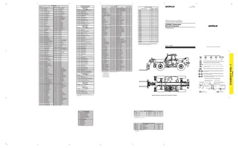
TH560B Telehandler Electrical System
1 2
Component Part Number
Sure-Seal connector: The plug and receptacle contain both pins and sockets.
42 Page
Wire Color
Wire Number
31200311 VOL 1
Wire Description Wire Number