Machine Location
Schematic Location
206-5502 194-0952
1
A-5
(220) 278-2112 (330) 253-2574
2
G-4
295-3424
3
B-2
(220/330) 295-3374 (340) 295-3419
4
H-6, H-7
5
G-5
Cooler & Mtg Gp Hydraulic Oil (Xmsn) (Option)
(12kW) (20kW)
Cylinder Gp Boom (Raise) Cylinder Gp - Brake (Master) Cylinder Gp - Coupler Cylinder Gp Tilt
(220) 187-3694 (330) 295-3372
Cylinder Gp Hydraulic (Compensating)
(220) 187-3695 (330) 187-3699
Cylinder Gp Telescoping
(220) 283-6315 (330) 295-3463
FLUID POWER SYMBOLS
31200275 December 15, 2006
BASIC COMPONENT SYMBOLS MAIN AUX.
PUMP or MOTOR
18 23 24 25
14 15
2
7
29
8
26 28 32 33
12 38
31 34
TWO POSITION
7
5
G-5
16 17 27
G-7
Filter Gp - Oil (Power Train) Motor Gp Fan (Reversing Motor)
191-1060
9
B-5
(220/330) 256-2843
10
I-10
Pump Gp Fan (Reversing Fan)
(220/330) 256-7180
11
I-9
Pump Gp - Metering (Steering - HMU)
233-6072
12
F-9
Pump Gp Piston (Main)
295-3457
13
B-10
202-5350
14
A-8
(202/330) 216-2258
15
A-8
Strainer - (Tank Filter) Tank As - Hydraulic
Valve & Mtg Gp - Diverter (Dual Auxiliary)
222-4662
16
H-8
Valve As - (Tilt Cylinder Lock) (Cartridge)
295-3372
17
F-6
Valve Gp - Bank 4 (Implement) Valve Gp - Check (Xmsn)
295-3450 257-4830
18 19
B-7 B-6
Valve Gp - Check (Back Pressure) 225-1912 Valve Gp Check (Coupler (220/330) 190-3611 Cylinder Check)
20
B-9
21
H-5, H-6
Valve Gp Combination (Trailer Services Valve) (Option)
22
H-2
227-1207
23
D-6
Valve Gp - Control (Aux) Valve Gp Control (Boom Extend, Retract)
227-1206
24
D-7
Valve Gp - Control (Boom Raise, Lower)
227-1209
25
D-5
Valve Gp - Control (Quick Coupler Tilt)
227-1208
26
D-6
Valve Gp - Diverter (Single Auxiliary)
295-3437
27
H-8, I-5
Valve Gp - Electronic Pilot
247-7829
28
B-4
29
G-3
Valve Gp Load Control (Boom Raise Lock)
(220/330) 229-2004
Valve Gp - Load Control (Tele Cylinder)
252-5652
31
F-6
Valve Gp - Manifold (Inlet)
227-1203
32
D-8
Valve Gp - Manifold (Outlet)
227-1205
33
D-4
Valve Gp - Pilot (Anti Kick)
216-4237
34
G-5
Valve Gp Relief (Reversing Fan) Valve Gp Solendoid (Reversing Fan)
(220/330) 264-0047
36
H-9
(220/330) 264-0048
37
I-10
210-7217
38
E-10
(5spPsy) 206-4386 (4spPsy) 206-4387 (4spPsh) 206-4388
39
A-6
Valve Gp - Solendoid (Steer Mode Select) XMSN Gp (Option)
P T SHIFTED POSITION
INFINITE POSITION
4
9
5
13 19 20 35 39
1
3
6
FLOW
13 19
7
Description
SOLENOID or MANUAL
SOLENOID
Main Pump Pressure
C-9
BB
Load Sensor Pressure
C-9
CC
Implement Pilot Pressure
C-3
DD
SOS Oil Sample Port
B-5
8
PUSH-PULL LEVER
29 31 34
MANUAL SHUTOFF
20 35 39 12 14 15 38
EXTERNAL RETURN
9
PILOT CONTROL SYMBOLS
21
SPRING LOADED
LINES CROSSING
HYDRAULIC PUMPS FIXED DISPLACEMENT
16 27
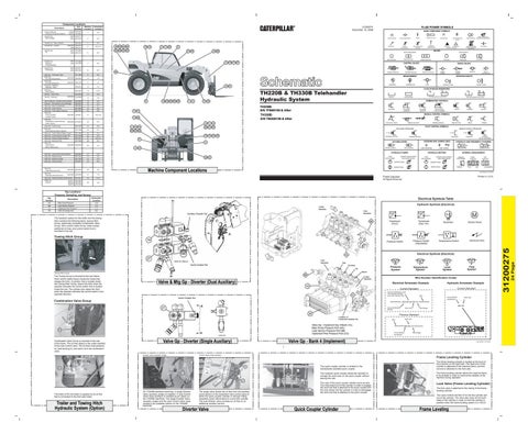
Machine Component Locations
FIXED DISPLACEMENT
INTERNAL PASSAGEWAYS
VARIABLE DISPLACEMENT NON-COMPENSATED
UNIDIRECTIONAL
BIDIRECTIONAL
BIDIRECTIONAL
DOUBLE ACTING
FLOW IN ONE DIRECTION
TWO POSITION
THREE POSITION
INFINITE POSITIONING
CROSS FLOW
PARALLEL FLOW
FLOW ALLOWED IN EITHER DIRECTION
Last Modified: 05/10/2004
Printed in U.S.A.
© 2006 Caterpillar All Rights Reserved
Electrical Symbols Table Hydraulic Symbols (Electrical)
Outlet Manifold
Inlet Manifold
BB
M
G Transducer (Fluid)
Transducer (Gas / Air)
Generator
Electric Motor
A 16
Pressure Switch (Adjustable)
Pressure Switch
Inlet Manifold
VIEW OF AREA A
Quick Coulper Sol.
Tele
T
Auxiliary
Pressure Symbol
Boom
Towing Hitch Group.
BB
Valve & Mtg Gp - Diverter (Dual Auxiliary)
Temperature Symbol
Outlet Manifold
18
Hydraulic Schematic Example Current Standard
Current Standard
CC
Flow Symbol
Level Symbol
Wire Number Identification Codes Electrical Schematic Example
Quick Coulper Sol.
Combination Valve Group
Electrical Wire
Temperature Switch
Electrical Symbols (Electrical)
Tilt
Harness identification code This example indicates wire 135 in harness "AG".
Wire
Circuit Number Identification
Wire Color
325-AG135 PK-14
B
27
B
Valve Gp - Diverter (Single Auxiliary) Diverter Valve (auxiliary single)
Wire Gauge
Wire Color
Wire
Valve Gp - Implement Asy 4-Bank (15), Main Pump Pressure Port (AA), Load Sensor Pressure Port (BB, Implement Pilot Pressure Port (CC)
VIEW B-B
Wire Color
Previous Standard
Location of Implement Disable Sol.
22
325-PK
Circuit Identification Number
28
325-PK-14 B Circuit Number Identification
(EXAMPLE VALVE)
Last Modified: 10/15/2003
Control Valve (dual auxiliary)
Frame Leveling Cylinder The quick coupler cylinder is located in the hydraulically operated quick coupler.
16 21
27
27
On TH220B standard machines, a single Diverter Valve (auxiliary single) is installed. A dual Control Valve (dual auxiliary) is installed as an option on the TH220B machines. The single Diverter Valve (auxiliary single) and the dual Control Valve (dual auxiliary) are available options on the TH330B machines.
The single valve diverts the oil flow from the auxiliary circuit section of the implement main control valve to either the quick coupler cylinder or through Fitting Assembly (quick disconnect) to a work tool cylinder. The dual diverter valve provides an oil flow to an additional auxiliary service.
Diverter Valve
A
Wire Gauge
Valve Gp - Bank 4 (Implement)
22
Trailer and Towing Hitch Hydraulic System (Option)
SINGLE ACTING
LINES JOINING
UNIDIRECTIONAL
INTERNAL SUPPLY PRESSURE
COMPLETE
HYDRAULIC AND PNEUMATIC CYLINDERS
HYDRAULIC MOTORS
VARIABLE DISPLACEMENT NON-COMPENSATED
SPRING
REMOTE SUPPLY PRESSURE
CROSSING AND JOINING LINES
GAS CHARGED
PEDAL
SIMPLIFIED
ACCUMULATORS
3
27
The brake oil for the trailer is supplied by an oil line that is connected to the front axle brake.
DETENT
THERMAL
PUSH BUTTON
INTERNAL RETURN
AA
Combination Valve Group is mounted to the rear of the frame. The oil lines attach to the outlet manifold of the main control valve. The oil lines route pressure oil, load sensing oil, and return oil to the combination valve.
GENERAL MANUAL
RELEASED PRESSURE
The hydraulic system for the trailer and the towing hitch contains the following items: towing Hitch Group, electrically controlled Combination Valve Group, hitch control Cable Group, trailer socket, additional oil lines, and control switch that is mounted in the cab.
The Towing Group is mounted to the rear frame. Hitch control Cable Group moves the hooks that release the hitch. A cylinder, that is located inside the Towing Hitch Group, lowers the hitch when the operator activates the control switch that is located inside the cab. The cylinder also raises the hitch when the operator activates the control switch in the opposite direction.
SERVO
MANUAL CONTROL SYMBOLS
Auxiliary Diverter Sol.
Towing Hitch Group
RETURN BELOW FLUID LEVEL
SOLENOID and PILOT or MANUAL
SOLENOID and PILOT
Schematic Location
AA
BIDIRECTIONAL
COMBINATION CONTROLS
Tap Locations Pressure, Sampling, and Sensor Tap Number
UNIDIRECTIONAL
RETURN ABOVE FLUID LEVEL
PRESSURIZED
TH330B: S/N TBG00100 & After
30
4
ROTATING SHAFTS
TEMPERATURE
VENTED
TH220B: S/N TFB00100 & After
17
PILOT CONTROLLED
FLUID STORAGE RESERVOIRS
TH220B & TH330B Telehandler Hydraulic System
30
2 1
PRESSURE
21
SHUTTLE
SPRING LOADED
BASIC SYMBOL
MEASUREMENT
6
(202/330) 215-2303
CHECK VALVES
AB
P T NORMAL POSITION
22
FOUR-WAY
THREE-WAY
CONTROL VALVES AB
8
ATTACHMENT
LINE RESTRICTION
VARIABLE and PRESSURE COMPENSATED
VALVE PORTS
TWO-WAY
THREE POSITION
PUMP: VARIABLE and PRESSURE COMPENSATED
2-SECTION PUMP
HYDRAULIC PNEUMATIC ENERGY TRIANGLES
VALVES
VALVE ENVELOPES
ONE POSITION
LINE RESTRICTION (FIXED)
RESTRICTION
PRESSURE COMPENSATION
LINE RESTRICTION (VARIABLE)
SPRING (ADJUSTABLE)
VARIABILITY
CONTROL VALVES
SPRING
FLUID CONDITIONER
24 Page
Part Number
Description
4
The frame leveling cylinder is located at the front of the machine on the right side. The head end of the cylinder is attached to the machine frame, and the rod end is attached to the front axle.
6
The hydraulic quick coupler allows the operator to change the work tools on the quick coupler without leaving the cab.
The frame leveling cylinder allows the machine frame to be levelled in order to improve the stability of the machine during operation.
The rods of the quick coupler cylinder serve as pins. The rods extend out of the cylinder in order to engage the work tool that is attached to the quick coupler and the rods retract into the cylinder in order to disengage the work tool that is attached to the quick coupler.
Lock Valve (Frame Leveling Cylinder) 30
The lock valve is attached to the casing of the frame leveling cylinder. The valve controls the flow of oil into the cylinder and out of the cylinder. The valve also locks oil into both sides of the cylinder in order to hold the cylinder in position when the frame leveling system is in HOLD.
Quick Coupler Cylinder
Frame Leveling
31200275
Component Locations