Wire Description Wire Number
Wire Color
Bat (+) (Not Application Specific)
516
GN
Blower Motor (Medium)
RD
Key Sw
517
BU
Blower Motor (Low)
RD
Horn
518
OR
Hazard Flasher To SW
112
PU
Main Power Rly Output
522
WH
A/C Clutch To Thermostat SW
113
OR
Opr Mon Panel VMIS B+ Switched
537
GN
Turn Signal SW To Flasher
114
GN
Warning Horn (Forward)
538
BR
Hazard Indicator
115
PK
Disable Relay R6
548
GY
Aux Hyd - Open
116
BR
Fuel Solenoid
549
PK
Aux Hyd - Close
119
PK
Rear Cab Wiper Motor
A513
PK
DC/DC Converter Memory Output
120
PU
Front Wiper Motor
A571
PU
Aux Ckt 1
122
BU
Heater 3 Speed Fan Switch
C509
WH
A/C Thermostat
123
WH
XMSN Mode Switch
124
BU
Cab A/C Unit
603
PK
Rotary Beacon
125
RD
Rear Steer Sensor
604
OR
Stop Lamp
128
PK
Hyd Control
605
YL
Turn Lamp - Left
RD
105 110
Accessory Circuits Cont.
Power Circuits
HYDROSTATIC TRANSMISSION ECM Transmission Solenoid (Reverse)
1 2
Battery Battery High Current 1 FB (-)
15 29 9
High Current 4 (+) High Current 5 (+)
22 24
200-BK 200-BK Transmission Solenoid (Forward)
1 2
Drive Pump Sol (Rev)
6
754-BU
Drive Pump Sol (Fwd)
7
752-YL
Transmission Switch
High Current 0 FB (-)
8
G750-BU
Selector Switch (Forward)
2
H731-GY
Selector Switch (Reverse)
3
To Motor Displacement Sol Battery + Mode Switch
28 4
42
Park Brake Switch Parking Brake Switch
Service Connector (Pin 2) Service Connector (Pin 3) Service Connector (Pin 5) Drive Pump Speed Sensor
5
20 21 13 16
C491-PU
Inching Pedal Sensor
Sensor -
14
31
1
G745-PK
BR
Boom Lamp Relay
617
F843-YL
PK
Hazard Switch
618
YL
Tail/Position Lamp - Right (Road Pkg)/Width
185
RD
Steer Aligned Lamp
619
GN
Head Lamp Lo
620
--!!
!!-!
-!-!
!--!
Main Chassis
627
YL
Fog Lamp
BK
AETA Coding Pin 20
652
YL
Right Front Flood
217
BK
XMSN Id Code 2
653
YL
Boom Working Lamp
CONN 5
667
OR
Front Floods - Aux
CONN 6
CONN 4
PU
Flood Lamp Rear (Atch)
CONN 8
306
GN
Neut Starter Relay Coil To Neut Start SW
A607
PK
Light SW to Side Flood Relay
CONN 9
307
WH
Key SW To Neutral Start Relay
A625
BR
Crane/Boom Flood Lamp Sw to Relay
CONN 10
5 6
308
YL
Main Power Relay Coil
309
GY
Alternator Regulator Term.
752
YL
XMSN Shift Sol No. 2
321
WH
Backup Alarm Lamp Travel Alarm
754
BU
XMSN Shift Sol No. 3 Or 1
322
GY
Warning Horn (Forward)
780
PU
Coupler Disengage Sol
323
WH
Fuel Pump Power
788
YL
Eng Speed (+)
A779
YL
Mechatronics Cont Sol5
405
GY
Oil Press SW
A780
GN
Mechatronics Cont Sol6
430
BU
Air Filter SW
G709
WH
Roading SW - Body Inhibit
441
OR
Eng Coolant Temp Gage
G710
GY
Jumper For Roading Relay
447
PK
Fuel Level Gage
G745
PK
Brake Pedal Sensor
YL
CONN 11
Control Circuits
Tach Sender (+)
G750
BU
BR
Brake Fluid Level
G797
BU
SW To Relay Coil
YL
Steering Oil Pilot Press
H702
PU
Impl Cont Reversing Fan SW (N.O.)
PU
Park Brake Pressure
H731
E455
BR
Hydraulic Oil Filter
GY
Forward Output - Shuttle Control
H750
BR
Steer Input #1
H751
OR
Steer Input #2
Wiper - Front (Park)
H764
GY
Rear Steer Position Snsr
Accessory Circuits 500
BR
501
GN
Wiper - Front (Low)
H765
WH
Front Steer Position Snsr
503
BR
Wiper - Rear (Park)
J764
BR
Switch/Sensor Return #1
Check the wiring. Check the sensor.
No signal is detected from the speed sensor during start-up.
Check the wiring. Check the sensor.
The circuit for one of the solenoids is open or shorted.
Check the wiring. Check the solenoid.
H-12
21
G-12
21
Beacon
H-11
28
Solenoid Aux 2B Out
H-12
21
YL
Wiper - Rear (Low)
F811
BR
RS232C Tx (Master)
(Slope Finish, HEDC)
506
PU
Washer - Front
F817
GY
RS232C Rx (Master)
(Slope Finish, HEDC)
507
WH
Washer - Rear
F843
YL
Inching Pedal Telescope In Sol
508
PU
Radio Speaker - Left
979
BU
509
WH
Radio Speaker - Left (Commom)
980
BR
Telescope Out Sol
511
BR
Radio Speaker - Right
G985
PU
Seat Switch
D-2
46
Solenoid Circle Steer
C-8
12
G-11
29
Solenoid Crab Steer
C-7
12
Font Water Pump
A-7
20
Solenoid Diverter
B-11
2
Front Wiper
E-2
36
Solenoid Extend
G-12
21
Fuel Solenoid
A-9
11
Solenoid Forward
B-7
18
Fuse Alternator
B-7
14
Solenoid Motor Displacement
H-1
38
Fuse Main
B-7
14
Solenoid Retract
G-12
21
Fuse Start Aid
B-7
14
Solenoid Reverse
B-7
18
Fuse Start Relay
B-7
14
Solenoid Reverse Fan
C-9
6
Glow Plugs
B-9
11
Solenoid Aux 1A In
G-12
21
Heater Unit
G-11
24
Starter
C-8/B-8
13
Inch Pedal
F-6
34
Starter Relay
Internal Power Socket
F-11
7
Switch
Joystick
D-7
48
Switch A/C
E-8
27
Light LH Cab Rear Working
H-11
3
Switch Air Filter
A-8
16
I-7
26
Switch Disconnect
A-6
44
Radio
512
GN
Radio Speaker - Right (Common)
N904
PU
Forward High Range Solenoid
513
OR
A/C Compressor/Refrigerant Pressure SW
P991
PK
Mode Select Sw
515
GY
Blower Motor (HI)
Correctly Routed Harness
Incorrectly Routed Harness
14
G-6/F-6
47
E-11
3
Switch Forward Colum
G-6
33
Rear Water Pump
A-7
20
Switch Heater 3 Speed Fan
E-8
27
Relay Aux Disable
G-9
25
Switch Hydraulic Disable
E-6
35
Relay Boom Lamp
G-9
25
Switch Hydraulic Filter
A-8
19
Relay Front Lamp
F-9
25
Switch Low Brake Pressure
C-5
43
Relay Hydraulic Disable
H-9
25
Switch Low Steer Pressure
C-7
17
Relay Main Power
H-6
32
Switch Oil Pressure
A-9
10
Relay Rear Lamp
F-9
25
Switch Parking Brake
I-11
39
Relay Side Lamp
G-8
25
Switch Steer Select
E-6
35
B-8
14
Switch Stop Lamp
D-11 D-11 B-9 D-6
4 5 11 42
Switch Trinary Switch Trinary Thermostat A/C
RH Cab Rear Working Light RH Cab Speaker Sender Temp Sender Fuel Level
H-1
41
G-11 G-11 G-11
30 30 5
Proper Harness Routing
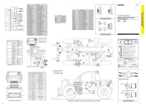
TH210 and TH215 Telehandler Electrical System TH210: MHT1-UP CEC501-UP
CORRECT
TH215: MHS1-UP CEG501-UP
Correctly Inserted Plug
Incorrectly Inserted Plug
Proper Plug Insertion
© 2011 Caterpillar, All Rights Reserved
Printed in U.S.A.
(1) POWER - The LED is green. The LED is illuminated when voltage is supplied from the key start switch. (2) SYSTEM - The LED is green. The LED is illuminated when the internal 5 volt supply is working.
Harness And Wire Electrical Schematic Symbols
10
(3) MODE - The LED is yellow. The LED will slowly flash when the program is running properly.
Hydrostatic Transmission ECM
20
(4) STATUS - The LED is red. The LED is illuminated when a diagnostic fault is detected. Refer to table 3 for more information on diagnostics.
45
14 19
Symbols
9
11
T
Pressure Symbol
16
44 18
Ignition Switch
+
B-8
Rear Cab Wiper Motor
Relay Start Aid
Check the wiring. Check the output voltage at the ECM.
The signal from the position sensor (inching pedal) is incorrect.
Solenoid Aux 1B Out Solenoid Aux 2A In
AVOID
504
1 2 3 4
Machine Location 1 2 3 4 5 5 5 6 7 7 7 8
XMSN Cont Fwd SW To Gnd
483
C491
Schematic Location C-12 I-11 A-11 A-10 D-9 D-9 D-8 A-4 F-2 G-2 H-2 I-2
CONN 12 The connectors shown in this chart are for harness to harness connectors. Connectors that join a harness to a component are generally located at or near the component. See the Component Location Chart.
C450
Possible Remedy
Temperature Symbol
Level Symbol
Circuit Breaker Symbol
Flow Symbol
Symbols and Definitions
15
Fuse: A component in an electrical circuit that will open the circuit if too much current flows through it.
13
Switch (Normally Open): A switch that will close at a specified point (temp, press, etc.). The circle indicates that the component has screw terminals and a wire can be disconnected from it.
_
Switch (Normally Closed): A switch that will open at a specified point (temp, press, etc.). No circle indicates that the wire cannot be disconnected from the component. Ground (Wired): This indicates that the component is connected to a grounded wire. The grounded wire is fastened to the machine.
Check the wiring.
Speed sensor signal is incorrect.
Check the wiring. Check the sensor.
--!-
Incorrect hardware
Replace the ECM.
----
A parameter is not set.
Replace the ECM.
(1)
CONN 3
683
Short circuit in the position sensor (transmission control lever)
---!
CONN 2
BK
STATUS
5 volt power supply is out of tolerance.
Flood Lamp - Front (Eng. Flood Lamp)
216
MODE
-!!!
YL
Connector Number CONN 1
200
POWER
Potential Cause
Tail/Position Lamp - Left (Road Pkg)/Width
161
SYSTEM
Diagnostic LED (4) (1)
BR
Connector Location
Starter Relay No. 1 Output
Sensor Signal Sensor +
7 45
Bucket Flood Lamp/Boom Flood Lamp
WH
Inching Pedal Position Sensor
B-9
Controller Xmsn susmic
GY
AVOID
Machine Location
A-6
Electric Seat
616
Schematic Location
Alternator
Cab Flood Lamp/Rops
Rear Work Lamp Switch
Component
Battery
PK
304
788-YL
15
615
450
Sensor +
1
A-8
Rear Wiper Washer Switch
CONN 7
Sensor + Signal
J764-BR
B-12
Sensor Speed
GN
Monitoring Circuits
200-BK
Sensor Rear Steer
22
144
Flood Lamp Rear (Atch)
Drive Pump Speed Sensor
5
H-12
Park/Tail/Dash/Lamp
OR
F817-GY
G-11
Alarm Backup
Turn Lamp - Right
681
F811-BR
AC Thermostat
PU
Key SW ACC Position
4
37
GY
Basic Machine Circuits
Service Connector Socket
9
H-1
614
YL
3
B-9
Sensor Front Steer
606
303
2
Sensor Engine Temp
7
Suppl Ster
1
123-WH
25
B-9
Radio
123-WH P991-PK
E-11
AC Compressor
RD
Mode Switch Battery +
Lighting Circuits
Ground Circuits
From Front Chasis Harness
A/C Unit (Cab)
GN
159
321-WH
Machine Location
136
BR
CORRECT
Component Location Schematic Location
Component
130
158
To Neutral Start Relay
RENR7697-02 September 2011
Description
6 Parking Brake Switch
F/N/R Position Switch
Inching Pedal Position Switch
3
17
Power Mode Rocker Switch
43
37
1
6
Ground (Case): This indicates that the component does not have a wire connected to ground. It is grounded by being fastened to the machine. Reed Switch: A switch whose contacts are controlled by a magnet. A magnet closes the contacts of a normally open reed switch; it opens the contacts of a normally closed reed switch.
2
Sender: A component that is used with a temperature or pressure gauge. The sender measures the temperature or pressure. Its resistance changes to give an indication to the gauge of the temperature or pressure.
T
38
35
27
46 Forward Solenoid
31 5
7
48
42
4
5 30
Reverse Solenoid
Relay (Magnetic Switch): A relay is an electrical component that is activated by electricity. It has a coil that makes an electromagnet when current flows through it. The electromagnet can open or close the switch part of the relay.
1 21
Solenoid: A solenoid is an electrical component that is activated by electricity. It has a coil that makes an electromagnet when current flows through it. The electromagnet can open or close a valve or move a piece of metal that can do work.
2 4 22
Magnetic Latch Solenoid: A magnetic latch solenoid is an electrical component that is activated by electricity and held latched by a permanent magnet. It has two coils (latch and unlatch) that make electromagnet when current flows through them. It also has an internal switch that places the latch coil circuit open at the time the coil latches.
3
Harness and Wire Symbols
36 12 Hydrostatic Pump
Hydrostatic Motor
8 47 7 41 25 34
Speed Sensor
24
39 28 23 3
Part Number: for Connector Receptacle
Plug
5
Connectors
Receptacle Pin or Socket Number
1 2
Deutsch connector: Typical representation of a Deutsch connector. The plug contains all sockets and the receptacle contains all pins.
1 2
Sure-Seal connector: Typical representation of a Sure-Seal connector. The plug and receptacle contain both pins and sockets.
5A 9X-1123
Fuse (5 Amps)
4
Harness identification code: This example indicates wire group 325, wire 135 in harness "AG".
CORRECT
3
MODE STATUS
Hydrostatic Transmission ECM
14
1
28
15
29
42
Connector Pin Orientation.
No.
Type
Function
1
Ground
Sensor Return
2
Input
Forward Switch
3
Input
Reverse Switch
4
Input
Work Mode Switch
5
Input
Parking Brake Switch
6
Output
Reverse Solenoid
7
Output
Forward Solenoid
8
Ground
Solenoid Return
13
Ground
Data Link
14
+ 5 Volts
Sensor Supply
15
Ground
- Battery Voltage
16
Input
Speed Sensor
20
Input/ Output
Data Link “TxD”
21
Input/ Output
Data Link “RxD”
28
Battery Voltage
+ Battery
29
Ground
- Battery Voltage
31
Input
Inching Pedal
42
Battery Voltage
+ Battery
Connector Socket (1)
Connector Pin (2)
INCORRECT The 8T-8729 Connector Pin (2) and the 8T-8730 Connector Socket (1) is designed to accept only one 16/18 AWG wire. Do not insert multiple wires of a smaller wire size. The 9W-0852 Connector Pin and the 9W-0844 Connector Socket is designed to accept only one 14 AWG wire. Do not insert multiple wires of a smaller wire size.
1
6 37
45
44 35
36
8
33
26 16
7 14 19 47 41 12 17 18 25 15 32 46 38 43 6 20 34 39
7
27
9
5
8
48
5 24
2
28 21
2 3 4
11 39
22
Seal Sealing Plug
Correct Installation
13 10
Component Part Number
325-AG135 PK-14
Two Speed Solenoid (Hydrostatic Motor)
Contact Description Of The Connector For The Electronic Control Module (Hydrostatic Transmission)
SYSTEM
L-C12 3E-5179
Harness Connector Serialization Code: The "C" stands for "Connector" and the number indicates which connector in the harness (C1, C2, C3, ...).
2
Components POWER
L-C12 3E-5179
1
Part Number: for Connector Plug
+ Two Speed Rotory Motor
Harness Identification Letter(s): (A, B, C, ..., AA, AB, AC, ...)
AG-C4 111-7898
26
Engine
! represents a short on-time. - represents a long on-time. ---represents continuous on-time.
32
29
33
Wire, Cable, or Harness Assembly Identification: Includes Harness Identification Letters and Harness Connector Serialization Codes (see sample).
42
1
Deutsch Sealing Plug Insertion Seal
29
Sealing Plug
Incorrect Installation
HARNESS CONNECTOR AND COMPONENT LOCATIONS
DT Type Sealing Plug
Wire Gauge Wire Color
(Dimensions: 48 inches x 35 inches)
101
Description
36 Page,
Wire Color
RENR7697-02
Wire Number