Component Locations Description VALVE GP - STEERING
Part Number
Machine Location
Schematic Location
203-6812
1
G-9
203-6804
2
G-7
200-1559
3
G-5
CYLINDER GP - BOOM
Note A Note B
209-3981 249-3645
CYLINDER GP - TILT
Note A Note B
209-3973 249-3642
CYLINDER GP - COMPENSATING
Note A Note B Note C Note B
7
E-3
BLOCK (MANIFOLD)
209-3971 249-3641 209-3976 249-3643 202-8210
8
F-3
HITCH GP - TOWING
216-5921
9
F-3
COUPLING - TRAILER BRAKE
200-1560
10
D-4
VALVE GP - TRAILER BRAKE
202-8222
11
D-4
TAP AS
202-8287
12
D-5
OIL COOLER AS
215-2273
13
C-4
MOTOR GP - PISTON (HYDROSTATIC)
203-6809
14
C-4
Note A 203-6808 Note B 262-4367
15
C-6
Note A 225-4927 Note B 237-7994 Note A 203-6806 Note B 235-8031
16
B-8
17
A-8
PUMP GP - PISTON (HYDROSTATIC) MOTOR GP - GEAR (FAN DRIVE) PUMP GP - GEAR (HYDRAULIC FAN)
7
25
6
4
25
20
22
PUMP GP - GEAR (HYDRAULIC) (IMPLEMENT, STEERING, AND BRAKING) Note A 203-6807 Note B 233-9591 FILTER GP - OIL (HYDRAULIC) 200-1547
1 MAIN AUX.
4
2
8
29
5
F-4
6
F-3
10 12 13
3 11
INFINITE POSITION
18
17 23
26
19
24
14
15
PRESSURE
5
TH210 & TH215 Telehandler Hydraulic System 7 8
ROTATING SHAFTS
FLOW
TEMPERATURE
25
D-9
VALVE GP - BRAKE CONTROL
203-6813
22
D-10
TANK GP - HYDRAULIC
209-8940
23
A-9
10 12 13
TANK GP - HEADER
211-7110
24
A-10
16 27 28
Note D 209-3977 Note B 249-3644
25
E-3
221-2209
26
B-10
VENTED
6
29
SOLENOID or MANUAL
5
PUSH-PULL LEVER
SERVO
SOLENOID and PILOT or MANUAL
SOLENOID and PILOT
GENERAL MANUAL
MANUAL SHUTOFF
1
20 INTERNAL RETURN
SIMPLIFIED
CROSSING AND JOINING LINES
GAS CHARGED
LINES CROSSING
HYDRAULIC PUMPS FIXED DISPLACEMENT
LINES JOINING
17 18 19
14 15
SINGLE ACTING
FIXED DISPLACEMENT
VARIABLE DISPLACEMENT NON-COMPENSATED
UNIDIRECTIONAL
UNIDIRECTIONAL
BIDIRECTIONAL
BIDIRECTIONAL
DOUBLE ACTING
INTERNAL PASSAGEWAYS
HYDRAULIC MOTORS
VARIABLE DISPLACEMENT NON-COMPENSATED
INTERNAL SUPPLY PRESSURE
COMPLETE
HYDRAULIC AND PNEUMATIC CYLINDERS
B-9 23 26
SPRING
REMOTE SUPPLY PRESSURE
ACCUMULATORS
11
PEDAL
PILOT CONTROL SYMBOLS
EXTERNAL RETURN
21
DETENT
THERMAL
PUSH BUTTON
RELEASED PRESSURE
3
9
Note A: Used only on CEC & CEG machines. Note B: Used only on MHS & MHT machines. Note C: Used only on CEC machines. Note D: Used only on CEG machines.
RETURN BELOW FLUID LEVEL
MANUAL CONTROL SYMBOLS
SPRING LOADED
29
BIDIRECTIONAL
RETURN ABOVE FLUID LEVEL
PRESSURIZED
SOLENOID
CYLINDER GP - TELESCOPING
203-6814
UNIDIRECTIONAL
COMBINATION CONTROLS
CEC1-500 CEG1-500 MHS1-UP MHT1-UP 4
21
D-5
PILOT CONTROLLED
FLUID STORAGE RESERVOIRS
200-1664
28
SHUTTLE
SPRING LOADED
BASIC SYMBOL
MEASUREMENT
ACCUMULATOR AS - BRAKE
Note A
CHECK VALVES
P T SHIFTED POSITION
P T NORMAL POSITION
21
FOUR-WAY
THREE-WAY
AB
24
27
TWO-WAY
THREE POSITION
CONTROL VALVES AB
D-8
TAP AS VALVE GP - MAIN CONTROL (IMPLEMENT - 5 SLICE)
TWO POSITION
ONE POSITION
2
B-7
VALVE PORTS
9
B-8
19
ATTACHMENT
LINE RESTRICTION VARIABLE and PRESSURE COMPENSATED
VALVES
16 27 28
18
PUMP: VARIABLE and PRESSURE COMPENSATED
2-SECTION PUMP
HYDRAULIC PNEUMATIC ENERGY TRIANGLES
VALVE ENVELOPES
20
Note A 219-6901 Note B 264-6580 202-8288
LINE RESTRICTION (FIXED)
RESTRICTION
PRESSURE COMPENSATION
LINE RESTRICTION (VARIABLE)
SPRING (ADJUSTABLE)
G-4
203-6803 214-1425
VALVE - FAN (BI-DIRECTIONAL)
CONTROL VALVES
SPRING
FLUID CONDITIONER
VARIABILITY
VALVE GP - ACCUMULATOR (CHARGING) Note A Note B
MOTOR GP - FAN
BASIC COMPONENT SYMBOLS
PUMP or MOTOR
VALVE GP - MAIN CONTROL (IMPLEMENT - 4 SLICE) VALVE GP - DIVERTER
CYLINDER GP - TELESCOPING
FLUID POWER SYMBOLS
RENR5161-01 February 2005
22 FLOW IN ONE DIRECTION
TWO POSITION
THREE POSITION
INFINITE POSITIONING
PARALLEL FLOW
CROSS FLOW
FLOW ALLOWED IN EITHER DIRECTION
G-7
Printed in U.S.A.
© 2005 Caterpillar All Rights Reserved
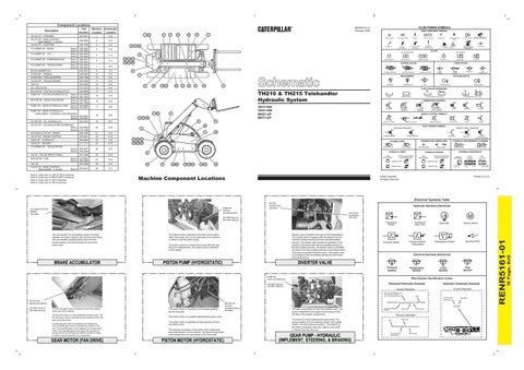
Machine Component Locations
Electrical Symbols Table
VALVE GP DIVERTER 200-1559
203-6808 (Note A) 262-4367 (Note B)
G Transducer (Fluid)
The accumulator for the braking system is located between the lower hydraulic tank and the main frame. The accumulator supplies pressurized oil to the service brakes in the front chassis by way of the brake valve
BRAKE ACCUMULATOR
The piston pump is attached to the front of the engine. Open the access door on the right side of the machine in order to view the piston pump.
Diverter valve is located in the rear service compartment. The diverter valve is equipped with connections for front mounted auxiliary services and rear mounted auxiliary services. The diverter valve permits the operation of one actuator at a time for either the front auxiliary services or the rear auxiliary services. The diverter valve is connected by hoses to the front auxiliary services at quick disconnects. The hoses are located inside the boom. The diverter valve is connected to the rear auxiliary services by short hoses and manifold block.
The piston pump is an axial piston pump that can vary the pump displacement. The piston pump is attached to the engine.
PISTON PUMP (HYDROSTATIC)
Transducer (Gas / Air)
Pressure Switch (Adjustable)
Pressure Switch
Generator
Electric Motor
Electrical Wire
Temperature Switch
Electrical Symbols (Electrical)
DIVERTER VALVE
T
Pressure Symbol
Temperature Symbol
PUMP GP GEAR (HYDRAULIC)
Flow Symbol
Level Symbol
Wire Number Identification Codes Electrical Schematic Example
203-6807 (Note A) 233-9591 (Note B)
Hydraulic Schematic Example Current Standard
Current Standard Harness identification code This example indicates wire 135 in harness "AG".
Wire Circuit Number Identification
MOTOR GP GEAR (FAN DRIVE) 225-4927 (Note A) 237-7994 (Note B)
M
The fan drive gear motor is located in front of the radiator at the rear of the machine.
The piston motor is mounted on the transfer gearbox for the front axle.
The fan drive motor is a fixed displacement gear motor. The fan drive gear motor is operated by the pressure oil from the gear pump (fan drive).
The piston motor is a variable displacement piston motor.
A reversible gear motor is available as an attachment. The reversible gear motor is operated by a switch in the cab. The reversible gear motor replaces the standard gear motor. The reversible gear motor allows the operator to reverse the air flow through the radiator and the oil cooler in order to remove dust from the components.
GEAR MOTOR (FAN DRIVE)
The piston motor is operated by high pressure oil from the piston pump. The direction of rotation of the piston motor determines the travel direction of the machine. The speed of the piston motor determines the input speed of the drive shaft.
PISTON MOTOR (HYDROSTATIC)
MOTOR GP PISTON (HYDROSTATIC) 203-6809
Wire Color
325-AG135 PK-14 325-PK
The gear pump draws oil from the hydraulic tank. The pump is attached to the engine front housing on the left side of the engine compartment. The pump is a fixed displacement gear pump. The pump supplies oil to the steering system, the braking system, and the implement system. The rotation of the shaft is clockwise when the rotation of the shaft is viewed from the drive end.
GEAR PUMP - HYDRAULIC (IMPLEMENT, STEERING, & BRAKING)
Circuit Identification Number
Wire Color
Wire Gauge
Previous Standard Wire Color
Wire
325-PK-14 B Circuit Number Identification
A
Wire Gauge (EXAMPLE VALVE)
16 Page, BJS
ACCUMULATOR AS BRAKE 200-1664
Hydraulic Symbols (Electrical)
RENR5161-01
PUMP GP PISTON (HYDROSTATIC)
BLOCK (MANIFOLD) 202-8210