KENR3058 October 1996
Harness And Wire Electrical Schematic Symbols 5
2
1
9
15
11
A
AA
10
Typical representation of a Deutsch connector. The plug contains all sockets and the receptacle contains all pins.
Receptacle
Plug
1 2
1 2
1
2
Typical representation of a Sure-Seal connector. The plugand receptacle contain both pins and sockets.
1314 Pin or Socket Number
3
Wire, Cable, or Harness Assembly Identification
Component Part Number
Single Wire Connector C
A
A
1
325-PK-14
Pin
8
7
6
9
4
AA
9X-1123 325-PK-14
Wire Color
Socket
12
2
Circuit Number Identification
5
1
2
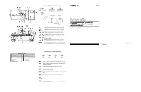
PS-150B Pneumatic Compactor PS-200B Pneumatic Compactor Electrical System
200-BK-14
Wire Gauge
Electrical Schematic Symbols And Definitions
7
6
9
4
11
FUSE - A component in an electrical circuit that will open the circuit if too much current flows through it.
1314
PS-150B: 3XR001-UP
PS-200B: 5JR001-UP
REED SWITCH - A switch whose contacts are controlled by a magnet. A magnet closes the contacts of a normally open reed switch; it opens the contacts of a normally closed reed switch.
15 12
SENDER - A component that is used with a temperature or pressure gauge. The sender measures the temperature or pressure. Its resistance changes to give an indication to the gauge of the temperature or pressure.
T
10
RELAY (Magnetic Switch) - A relay is an electrical component that is activated by electricity. It has a coil that makes an electromagnet when current flows through it. The electromagnet can open or close the switch part of the relay.
3
CIRCUIT BREAKER (C/B) - A component in an electrical circuit that will open the circuit if too much current flows through it. This does not destroy the circuit breaker and it can be reset to become part of the circuit again. SOLENOID - A solenoid is an electrical component that is activated by electricity. It has a coil that makes an electromagnet when current flows through it. The electromagnet can open or close a valve or move a piece of metal that can do work.
8
MAGNETIC LATCH SOLENOID - A magnetic latch solenoid is an electrical component that is activated by electricity and held latch by a permanent magnet. It has two coils (latch and unlatch) that make electromagnet when current flows through them. It also has an internal switch that places the latch coil circuit open at the time the coil latches.
Electrical Schematic Symbols And Definitions STANDARD COMPONENTS
Item
Component
No.
1
Item
Component
No.
Instrument Cluster
9
Batteries Starter Relay
Ignition Switch
10
3
Water Spray Motor
11
Starter Motor
4
Water Spray Switch
12
Alternator
Main Relay
13
Brake Solenoid Two Speed Solenoid Interlock Solenoid
2
5
Two Speed Switch
14
7
Horn Switch
15
8
Electrical Disconnect Switch
6
T
Pressure Symbol
Temperature Symbol
Level Symbol
Flow Symbol
Normally open switch that will close with an increase of a specific condition (temp-press-etc.). Normally open switch that is closed due to an applied condition, and will open again with a specific decrease in that condition.
Normally closed switch that will open with an increase of a specific condition.
Normally closed switch that is open due to an applied condition, and will close again with a specific decrease in that condition.
The circle indicates that the component has screw terminals and a wire can be disconnected from it.
No circle indicates that the wire cannot be disconnected from the component.
This indicates that the component has a wire connected to it that is connected to ground.
This indicates that the component does not have a wire connected to ground. It is grounded by being fastened to the machine.
© 1996 Caterpillar All Rights Reserved
Printed in U.S.A.