KENR1648 June 1990
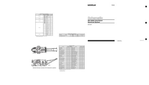
Harness Connector Location Chart Machine Location
Connectors
Harness And/Or Components
WW-7R9109 Diagnostic Connector (3208) XX-7R9110 Diagnostic Connector (3412)
1
20 Contacts 1 9 Contacts
Schematic Location B-5 C-5
2
AT - 7R9114 YY-7R9111
D-4
2
AT-7R9114 AV — 7R91 08
A-3
2 2
AT-7R9114 AW—7R9113
C-4
2
AB-7R9112 AT—7R9114
E-4
*
AT—7R9114 Rt. Console E-Stop
F-1
*
AT—7R9114 Lt. Console E-Stop
F-4
*
AW-7R9113 Rt. Front E-Stop
A-5
*
AW—7R9113 Lt. Front E-Stop
F-5
*
AW-7R9113 Cutter Door E-Stop
D-4
*
AW-7R9113 Rt. Rear E-Stop
A-9
*
AW-7R9113 Lt. Rear E-Stop
F-9
*
AW—7R9113 Cutter door Inductor Sw
A-7
*
AW-7R9113 Kickback Inductor Sw
7 Contacts
6 Contacts
4 Contacts
A-8
Machine locations are repeated for connectors located close together. * = Connector is located at the component.
PR-1000C Cold Planer Electrical System 5XC138-UP
Part No.
Function
6T7663
Engine Oil Pressure (S. Meter)
9D7032
Reverse Pressure
Off Machine Switch Specification Actuate
93 ± 21 kPa (13.5 ± 3.0 psi) 517 ± 35kPa (75.0 ± 5.0 psi)
Deactuate
69 ± 21 kPa (10.0 ± 3.0 psi) 414 ± 35kPa (60.0 ± 5.0 psi)
Contact Position Normally Open Normally Open
© 1990 Caterpillar All Rights Reserved
9
22
13
21 2
B
24
8
35
3
34
23
A
19 15
36 2
33
4
37
12
18 20
28
31 29
5
11
25 30
16
17
Alarm - Backup
1
1
38
Component
10
32
26 27
6
A
5 8 2
38 24
19
15
9 6
17
7
31
26
21 13 23 22
14
33
30
1 29 16
B 3
2
36
25 28 12
4 34
35
37
32
11
27 20 1
18 14
7 10
Machine Harness Connector And Component Locations
Schematic Location C-9
Component Location Machine Location 1
Component Relay -(3) Starter
Schematic Location C-6
Machine Location B 21
Alarm - Overheat
A-3
A
Relay - E Stop*
B-2
Alternator (3208)
C-8
2
Relay - E Stop*
B-5
B
Batteries
A-6
3
Relay - Kickback
B-2
22
Box - Cutter Door E-Stop* AS
D-4
4
Relay - Main
B-6
B
Box - Left Console E-Stop* AS
F-4
5
Relay - Reverse
B-3
23
Box - Left Front E-Stop* AS
F-5
6
Resistors (2.7 Ohms)
C-2
24
Box - Left Rear E-Stop* AS
F-9
7
Sender - Coolant Temp (3208)
B-8
25
Box - Right Console E-Stop* AS
F-i
8
Sender - Coolant Temp (3412)
E-6
26
Box - Right Front E-Stop* AS
A-5
9
Sender - Hydraulic Oil Temp
F-8
27
Box - Right Rear E-Stop* AS
A-9
10
Sender - Oil Pressure (3208)
B-7
28
Breaker - Alternator (3208)
D-8
11
Sender - Oil Pressure (3412)
E-5
29
Breaker - E-Stop*
B-6
B
Solenoid - Cutter Drum Clutch
C-4
A
Breaker - Main
B-6
B
Solenoid - Fuel (3208)
E-8
30
Breaker - Start
C-6
B
Solenoid - Fuel (3412)
E-5
31
Clutch - Water Spray Mag
E-8
12
Solenoid - Water Valve
B-7
32
Flasher
A-2
13
Switch - Coolant (High Temp)
E-5
33
Gauge - Coolant Temp (3208)
E-2
A
Switch - Cutter Clutch
C-4
A
Gauge - Coolant Temp (3412)
E-2
A
Switch - Cutter Door Inductor
A-7
34
Gauge - Hydraulic Oil Temp
F-3
A
Switch - Engine Rack Ught
E-6
A
Gauge - Oil Pressure (3208)
F-2
A
A-4
A
Gauge - Oil Pressure (3412)
F-3
A
A-4
A
Gauge - Pyrometer (3412)
E-3
A
A-4
A
Horn - Warning
A-2
14
Switch - Flasher and Beacon Switch - Flood Lamp (Conveyer, Cutter Floods) Switch - Flood Lamp (Dash Lamps, Front Floods) Switch - Key Start
D-2
A
Horn - Warning
0-5
15
Switch - Kickback Ski Inductor
A-8
35 36
Lamp - Kickback Reset
C-4
A
Switch - Main Disconnect
A-6
Meter - Service
E-7
A
Switch - Neutral Limit
D-2
A
Meter - Volt
E-2
A
Switch - Oil Pressure
D-7
37
Motor -(2) Starter Aft (3412)
D-6
16
Switch - Reverse Pressure
B-3
A
Motor -(3) Starter Forward (3412)
D-5
17
Switch - Spray Bar
B-4
A
Motor - Starter (1) (3208)
C-8
18
Switch - Start
D-3
A
Pickup - Magnetic (3412 Tach)
E-4
19
Tachometer - (3208)
E-2
A
Pickup - Magnetic (3208 Tach)
0-7
20
Tachometer - (3412)
E-3
A
Relay -(2) Starter
C-6
B
Thermocouple
E-5
38
Machine locations are repeated for components located close together. A = Components on operator console. B = Components on relay panel. * = E-Stop represents machine stop
Printed in U.S.A.