2 minute read
Weekly ..................................................................... 5


BI632977
crawler track take-up bearings Weekly
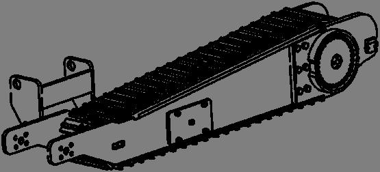
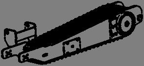
Lubricate the right and left hand crawler track take-up bearings (Fig. 33). The fittings (one per side) may be reached through the slot in the end of the crawler frame on the outside of each crawler. Pump grease into the fitting until new grease can be observed coming out of the bearings.
Fig. 33: Crawler track take-up lubrication
conveyor chain tension
fasteners
electrical cables, conduits and glands
hydraulic hoses and fittings
Crawler take-up grease fitting location (Typical both sides)
Check the conveyor chain tension. With the machine running, visually inspect tail shaft to ensure shaft is turning and conveyor shaft is not sliding across tail shaft. If adjustment is necessary, see Conveyor chain adjustment procedure in this chapter.
Due to the machine being subjected continual shock loading and vibration, close attention to all mounting bolts and screws is required. Loose fasteners will cause premature wear and failure to bearings, couplings, etc. Inspect and tighten as required the following fasteners:
■ head shaft bearing bolts
■ breaker shaft side plate bolts
■ conveyor drive motor mounting bolts
■ tail shaft retainer hold down bolts
■ all cover and guard retaining bolts
Visually inspect all electrical cables and glands for signs of wear or damage.
Visually inspect all hydraulic hoses and fittings for signs of wear, damage or leakage. This inspection should be performed with machine running.
Check the hydraulic system pressure (s) by visually looking at the pressure gauges. Refer to the hydraulic schematic in your parts manual for correct pressure (s).
hydraulic system pressure (s)
tram reducer (s)
Check the oil level in both tram reducer torque hubs (Fig. 35):
Oil level/fill plug should be at the 3 o’clock and 12 o’clock position.
Remove the oil level/fill plugs.
The oil level should be kept at the level of the level/fill plug.
Should it be necessary to add oil, add 80W-90 oil through the fill plug hole until it begins to flow out of the check hole.
Do not overfill the reducer.
Fig. 35: Tram reducer oil level
Drain plug location Fill plug location
Check plug location
BI632977
breaker reducer
Check oil level in the breaker drive reducer (Fig. 36). Oil level should be maintained inside the sight glass on the side of the reducer when it is in operation. If the reducer does not have a sight glass, a pipe plug will be installed in the side of the reducer slightly below the input shaft center line. This is the level that the fluid should be maintained at. The oil should be changed after the first 500 hours of operation. Use Century 220 lubricant.
Fig. 36: Breaker reducer
Inspection cover Breather
Drain plug
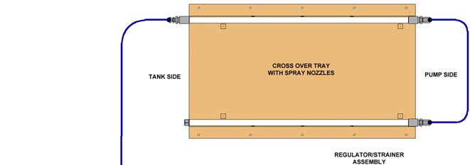
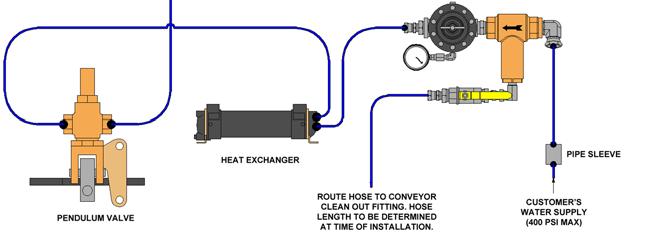
dust system strainer Clean the strainer mounted inside the dust suppression system. Open ball valve (Fig. 37) and allow water to flow from the short attached hose. The flowing water will flush out the filter strainer.
IMPORTANT! A short hose is attached to ball valve in dust suppression system to allow water to be directed away from other machine components.
Fig. 37: Dust system