Wire Color
101
RD
102
Wire Description Wire Number
Wire Color
Bat (+)
577
PU
Rear Wiper
BU
Head Lamp Sw, Dome Lamp, Steer Col Sw
585
YL
Func Lock Sw to Boom Ctrl Sw
103
YL
Func Lock Sw
A546
GN
Boom Ctrl Sw to Aux A Relay (coil)
105
BR
Key Sw
A546
BU
Boom Ctrl Sw to Aux A Relay (coil)
108
RD
B+ Radio
A547
PU
Boom Ctrl Sw to Aux B Relay (coil)
112
PU
Main Power Rly Output to Fuses
A547
OR
Boom Ctrl Sw to Aux B Relay (coil)
113
OR
Indicator Lights (Power)
114
GN
Warning Horn Sw (Forward)
603
PK
Rotary Beacon
114
GY
Warning Horn Sw (Forward)
604
OR
Stop Lamp
115
PK
Stabilizer Switches
605
YL
Turn Lamp - Left
116
BR
Frame Level Sw
606
GY
Turn Lamp - Right
117
YL
Speed Limiter
607
PK
Flood Lamp
118
GY
Front Wiper Sw
610
OR
Head Lamp Relay to Steer Col Sw
119
PK
Rear Wiper/Washer Sw
611
PU
Head Lamp Hi
123
WH
Power to Gauges, Hi Cool Temp Alarm
614
PU
Head Lamp Sw to Lamp Fuses
Ground - Subframe
124
GN
Heater Sw
617
BR
Tail/Position Lamp - Left & Plate Lamp
126
PK
Park Brake Sw
618
YL
Tail/Position Lamp - Right
130
GN
Flood Lamp Sw
619
GN
135
BU
Not Used
622
136
GN
Steer Select Sw
627
144
GN
Beacon Sw
147
PU
Lockout Rly to Stab Fuse and Frame Lvl Fuse
157
YL
Haz Warn Sw (Turn Sig Ckt)
161
PK
162
Description Power Circuits
Description
Schematic Location D-15
Component
Accessory Circuits (Continued)
Alarm - Backup
Component Location Machine Location 1
Component Solenoid - 2nd
Schematic Location A-11
Machine Location 2
Alarm - High Coolant Temp
I-13
C
Solenoid - Advance
F-13
2
Alternator
F-14
3
Solenoid - Aux_A
A-14
8
Assembly - Heater
I-13
B
Solenoid - Aux_B
A-14
8
E-16
14
Battery
E-14
9
Solenoid - Aux_Div
Control - Platform
G-1
D
Solenoid - B_Ext
A-15
5
A-8, A-9
A
Solenoid - B_Lower
A-14
5
I-14
24
Solenoid - B_Raise
A-15
5
L-17
B
Solenoid - B_Ret
A-15
5
J-17, I-17
B
Solenoid - C_O
A-15
5
C-5
A
Solenoid - Crab
G-13
12
Gauge - Fuel Level
C-5
A
Solenoid - D_Lock
A-13
8
Gauge - Transmission Oil Temp
B-5
A
Solenoid - Div_1
A-13
8
Ground - Cab
D-17
7
Solenoid - Div_2
A-13
8
Ground - Dash
J-5
C
Solenoid - Div_3
A-12
8
B-13, C-13
15
Solenoid - E-Stop
F-12
13
Heater
F-15
B
Solenoid - Frame Level
E-15
2
Horn
D-10
A
Solenoid - FWD
A-12
2
Head Lamp Lo
Indicator - Display
J-15
21
Solenoid - FWS
G-13
12
PU
Flood Lamp Sw (TUV)
Indicator - Load
I-15
C
Solenoid - High
A-11
2
YL
Fog Lamp
Lamp - Boom Flood LH_RR
E-2
22
Solenoid - LH_Stab_Down
G-3
25
629
PK
Head/Flood Lamp Sw to Head Lamp Relay
Lamp - Boom Flood RH_RR
634
WH
Headlamp / Side Sw (TUV)
Lamp - Indicator Light Gp
Haz Warn Sw (Haz Ckt)
720
PU
XMSN Neutralizing Relay (contact)
YL
Aux Sw
727
GN
165
YL
Diff Lock Sw
728
174
PK
Load Indicator
751 752
200
GN
Main Chassis
754
200
BK
Main Chassis
755 762
Control - Transmission
Lighting Circuits
Diode - Transmission Flasher Fuse Block Gauge - Cool_Temp
D-2
22
Solenoid - LH_Stab_Up
H-3
25
I-4, J-4
18
Solenoid - Rel_Sig
A-13
14
Lamp - LH Fog Or Reverse
F-18
18
Solenoid - Rev
A-12
2
Lamp - LH Head Turn
K-1
A
Solenoid - RH_Stab_Down
G-3
25
Prox Sw (Load) to Steer Relay (coil)
Lamp - LH Head Turn Pos
I-1
A
Solenoid - RH_Stab_Up
H-3
25
BU
Prox Sw (Supply) to Steer Relay (contact)
Lamp - LH License Plate
E-18
18
Solenoid - Tele_Out
A-12
8
GN
XMSN High Sol
Lamp - LH Stop/Tail
F-18
18
Solenoid - Tilt_1
A-12
8
YL
XMSN Fwd Sol
Lamp - LH Stop/Tail TUV
G-18
18
Solenoid - Tilt_2
A-12
8
BU
XMSN Rev Sol
Lamp - LH Turn
F-18
18
Solenoid - Tow Hitch Down
E-13
9
OR
XMSN 2nd Sol
Lamp - LH Turn TUV
G-18
18
Solenoid - Tow Hitch Up
D-13
9
YL
Lockout Relay to Boom Sensor
Lamp - License Plate
G-18
18
Switch - (A) Steer Select
I-7
A
Control Circuits
Ground Circuits
Monitoring Circuits 304
WH
Starter Relay Output
764
PU
Steer Select Sw B
Lamp - RH Fog Or Reverse
E-18
18
Switch - (B) Steer Select
H-7
A
306
GN
Neut Start Relay (contact) to Start Relay (coil)
766
GN
XMSN Control Sw
Lamp - RH Head Turn
J-1
9
Switch - Aux
D-6
A
307
OR
Key Sw to Neut Start Relay (contact)
B752
GN
Frame Level Sw to Sol
Lamp - RH Head Turn Pos
I-1
9
Switch - Beacon
F-6
A
308
YL
Main Pwr, Headlamp Rly, Backlights
B753
YL
Frame Level Sw to Sol
Lamp - RH License Plate
E-18
18
Switch - Boom Control
K-15
C
310
PU
Cold Start Relay Coil
E783
WH
Lowering Relay to D_EngLow Sw
Lamp - RH Rear TUV
F-18
18
Switch - Boom Low
E-1
D
317
YL
Start Aid Relay To Start Aid Sol
G769
GN
Lockout Relay
Lamp - RH Stop/Tail
E-18
18
Switch - Boom Prox
F-2
22
321
BR
Reverse Lamp, Backup Alarm
H708
OR
Boom Prox Switch
Lamp - RH Stop/Tail TUV
F-18
18
Switch - Brake Pedal
H-10
6
322
GY
Warning Horn (Forward)
H709
OR
Boom Prox Switch
Lamp - RH Turn
E-18
18
Switch - Cold Start
E-6
A
324
BU
Differential Lock Sol
H717
BR
Boom Speed Platform Control
Lamp - RH Turn TUV
G-18
18
Switch - Diff_Lock
G-6
A
327
PK
Func Lock Sw to Tilt Sol, Lockout Relay
J755
BU
Left Frame Level Solenoid Return
Motor - D_Eng_Low
B-17
27
Switch - Disconnect
E-15
26
329
YL
E Stop Sol
J756
BR
Right Frame Level Solenoid Return
Motor - Fan
330
YL
Neutral Start Relay Coil, Park Brake Sw
J757
PU
LH O/R Up Sol Return
Motor - Front Washer
332
BU
Lockout Sw to Func Lock Sw
J758
PK
LH Stabilizer Sw
Motor - Front Wiper
A314
OR
Park Brake SW to Trans Neutralizer Relay Set
J758
BU
LH Stabilizer Down Solenoid
Motor - Roof Washer
A315
WH
Park Brake Sw to Trans Neutralizer Rly Reset
J759
GN
RH O/R Up Sol Return
Motor - Roof Wiper
A318
BU
Platform Control and Boom Low Sw
J760
Switch - Engine Start
G-1
D
2
Switch - Engine Stop
G-1
D
H-1
A
Switch - Engine_Cool_Temp
F-12
14
G-13
2
Switch - Fan
L-2
20
I-3
7
Switch - Flood Lamp
D-6
A
RH O/R Down Sol Return
Motor - Starter
F-15
4
Switch - Flood Lamp
J-3
A
A-17
1
Switch - Frame Level
H-14
C
A-15
13
Switch - Func_Lock
B-6
24
818
BR
Indicator Sw
819
GY
Indicator Sw
Pres_Red
E893
BR
Reeling Drum to Platform Control
Reeling Drum
G-3
D
Switch - Hazard Warning
H-7
A
900
PU
XMSN 1st Sol
Relay - Aux A
L-14
C
Switch - Head_Flood_Lamp TUV
J-3
A
Oil Temp Gauge
910
YL
XMSN Neut Rly to Neut & Brk SW
Relay - Aux B
K-14
C
Switch - Headlamp/Side
G-7
A
PK
Fuel Level Gauge
979
BU
Tele Div Relay
Relay - Cold Start
F-14
2
Switch - Headlamp/Side TUV
K-3
A
GY
High Coolant Temp Sw
979
WH
Div Sols
Relay - Headlamp
J-17
B
Switch - Heater
I-14
C
Accessory Circuits
980
BR
Telescope Out Sol
Relay - Lockout
K-17
B
Switch - High_Cool_Temp
F-12
13
Boom Raise Platform Cntrl
Relay - Lockout
J-18
B
Switch - Horn
H-5
A
K-18
B
Switch - Indicator
E-2
C A
GN
Alternator (R) Term to Serv Meter
405
GY
Oil Press Sw
441
OR
Eng Coolant Temp Gauge
444
BU
447 F401 500
20
Plug - Jumper
Monitoring Circuits 403
YL
L-1 G-13
BR
Wiper - Front (Park)
981
GN
501
GN
Wiper - Front (Low)
982
GY
Boom Lower Platform Cntrl
Relay - Lowering
502
OR
Wiper - Front (HI)
985
GY
Crab Steer Sol
Relay - Main
K-17
B
Switch - LH Stabilizer
F-7
Four Wheel Ster Sol
Relay - Neutral Start
K-17
B
Switch - Master Steer
E-6
A
WH
Tele Div Relay (coil)
Relay - Start
G-14
2
Switch - Oil Pressure
F-12
14
506
PU
Washer - Front
986 A979
OR
507
WH
Washer - Rear
508
PU
Radio Speaker - Left
A980
PK
Tele Out Relay (coil)
Relay - Steer
J-17
B
Switch - Park Brake
J-13
C
511
BR
Radio Speaker - Right
C916
OR
Stab Sw to RH O/R Up Sol
Relay - Tele_Div
L-14
C
Switch - Proxy
A-16
23
515
GY
Blower Motor (HI)
C917
YL
Stab Sw to RH O/R Down Sol
Relay - Tele_Out
K-14
C
Switch - Rear/Fog Lamp
G-7
A
517
BU
Blower Motor (Low)
C918
GN
Stab Sw to LH O/R Up Sol
Relay - Transmission Neutralizing
L-17
B
Switch - RH Stabilizer
F-7
A
518
OR
Haz Sw to Flasher
C919
PU
Stab Sw to LH O/R Down Sol
Sender - Coolant Temp
E-12
17
Switch - Roof Wiper Washer
E-6
A
536
WH
Hazard Sw to Steer Col Sw & Flasher
G943
BU
Boom Low Sw
Sender - Fuel Level
H-12
10
Switch - Service Brake
H-13
C
546
BU
Aux A Sol
G969
YL
Tilt Sol Return
Sender - Transmission Oil Temp
F-12
11
Switch - Start
L-6
A
547
OR
Aux B Sol
N918
YL
Speed Limiter to Pressure Sw
Sensor - Strain
H-16
15
Switch - Steering Column
E-4
A
548
GY
Aux Div Sol
P978
GN
Press Sw to Speed Sensor
Service Meter
B-5
A
Switch - Transmission Neutral
F-6
A
Solenoid - 1st
A-11
2
Electrical Schematic Symbols And Definitions
T
Pressure Symbol
Normally open switch that is closed due to an applied condition, and will open again with a specific decrease in that condition.
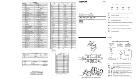
TH62, TH63, TH82, And TH83 Telehandler Electrical System
Normally closed switch that will open with an increase of a specific condition.
Normally closed switch that is open due to an applied condition, and will close again with a specific decrease in that condition.
4TM4014-UP 5WM6021-UP 3JN1510-UP 3RN4015-UP
The circle indicates that the component has screw terminals and a wire can be disconnected from it.
No circle indicates that the wire cannot be disconnected from the component.
This indicates that the component has a wire connected to it that is connected to ground.
This indicates that the component does not have a wire connected to ground. It is grounded by being fastened to the machine.
D
Harness And Wire Electrical Schematic Symbols
1 Receptacle
Plug
123-2844 3E-7504 7W-1238
Service Brake Pressure High Coolant Temperature Oil Pressure
Actuate 1000 kPa (145 psi) 107 ± 3 °C (225 ± 37 °F) 76 ± 21 kPa (11 ± 3 psi)
Deactuate 2000 kPa (290 psi) 98°C (208°F) -
Sender Specifications
Part No. 3T-7076
Component Description Sender: Coolant Temperature
8I-3814
Sender: Fuel Level
Normally Open Normally Closed
Form Number
Alternator:
SENR5841
Electric Starting Motor:
SENR3828
Powertrain Control:
SENR5839
CONN 2
C-18
1
CONN 3
D-17,E-16, G-16
1 1 C
CONN 6
F-15
17
CONN 7
D-15
15
CONN 8
C-15
15
CONN 9
E-14
17
CONN 10
E-14
17
CONN 11
F-14
17
CONN 12
G-14
7
CONN 13
G-14
A
CONN 14
I-14
A
CONN 15
J-15, K-14, J-13
C
CONN 16
F-10
19
240 Empty
CONN 17
K-10
19
72-82 @ 110° C (230°F)
CONN 18
L-10
19
CONN 19
B-9
19
CONN 20
B-9
19
CONN 21
B-9
19
CONN 22
C-9
19
CONN 23
G-3
18
CONN 24
D-3
9
CONN 25
F-2
22
CONN 26
H-2, I-2, J-2
9
CONN 27
H-2, I-2, J-1
A
CONN 28
A-11
25
CONN 29
F-10
19
CONN 30
B-8,B-7
24
CONN 31
K-5,K-3,L-3
19
CONN 32
E-3
22
560-716 @ 54° C (130°F)
Title
1
C-17
33 Full
Related Electrical Service Manuals
C-18
K-15,J15
72-82 @ 110° C (230°F)
¹ At room temperature unless otherwise noted.
CONN 1
CONN 5
Resistance (Ohms)¹
Sender: Transmission Oil Temperature
Machine Location
CONN 4
560-716 @ 54° C (130°F)
8I-6428
Schematic Location
Connector Number
Normally Closed
Wire, Cable, or Harness Assembly Identification
Pin or Socket Number
Connector Location
Contact Position
Component Part Number
2
D = Located on front of boom.
CONN 33 B-17 1 The connectors shown in this chart are for harness to harness connectors. Connectors that join a harness to a component are generally located at or near the component. See the Component Location Chart.
* C-C4* AG-C3 130-6795 130-6795
9
8
2 26
14
5
11
D
22
3
27
4
A
24
C
7 21
19
B
6
18
1
20
9X-1123
1
Harness identification code This example indicates wire 32 in harness "L'.
2
200-L32 BK-14
Socket
Single Wire Connector
15
12
25
Pin
23
17
L-C12* 3E-5179
AG-C4* 111-7898 325-A135 PK-14
13
Typical representation of a Sure-Seal connector. The plug and receptacle contain both pins and sockets.
Typical representation of a Deutsch connector. The plug contains all sockets and the receptacle contains all pins.
L-C12 * 3E-5179
AG-C4 * 111-7898
1 2
1 2
Part Numbers For Connector Assembly
C = Located inside right console.
Off Machine Switch Specification
Printed in U.S.A.
© 2000 Caterpillar All Rights Reserved
A = Located in dash area. B = Located under seat.
Function
Flow Symbol
Level Symbol
Normally open switch that will close with an increase of a specific condition (temp-press-etc.).
Machine locations are repeated for components located close together.
Part No.
Temperature Symbol
325-L25 PK-14
Wire Number
RENR3415 September 2000
* Harness identification letter(s) and a serializing code. The "C" stands for connector and the number indicates which connector in the harness.
Circuit Number Identification
Wire Color
Wire Gauge
10
Electrical Schematic Symbols And Definitions
16
FUSE - A component in an electrical circuit that will open the circuit if too much current flows through it. REED SWITCH - A switch whose contacts are controlled by a magnet. A magnet closes the contacts of a normally open reed switch; it opens the contacts of a normally closed reed switch. 7
20 T
21
22
A 26
B
25
12
11 16
9
2
18
3
6 D
5
13
C 14
24
4 8
19 1
17 27
10 15
23
SENDER - A component that is used with a temperature or pressure gauge. The sender measures the temperature or pressure. Its resistance changes to give an indication to the gauge of the temperature or pressure. RELAY (Magnetic Switch) - A relay is an electrical component that is activated by electricity. It has a coil that makes an electromagnet when current flows through it. The electromagnet can open or close the switch part of the relay. CIRCUIT BREAKER (C/B) - A component in an electrical circuit that will open the circuit if too much current flows through it. This does not destroy the circuit breaker and it can be reset to become part of the circuit again. SOLENOID - A solenoid is an electrical component that is activated by electricity. It has a coil that makes an electromagnet when current flows through it. The electromagnet can open or close a valve or move a piece of metal that can do work.
Machine Harness Connector And Component Locations