Part No. 3E-1906
Resistor, Sender and Solenoid Specifications Component Description
Solenoid:
8C-3663
8U-6424
172-7029
112-7178
116-4710
122-2373
Solenoid:
Solenoid:
Solenoid:
Sender:
Sender:
Resistor:
Resistance (Ohms)¹
A/C Clutch Engine Start/Stop Blade Front Blade Rear Hammer Heavy Lift Left Front Stabilizer Lockout Left Rear Stabilizer Lockout Parking Brake Right Front Stabilizer Lockout Right Rear Stabilizer Lockout Transmission Speed
19
OSC Axle Lock Creeper Speed Swing Brake Travel Activation Implement Activation
33.8/17 Watt
Fuel Level
Full = 0.4 Empty = 70.6
Hydraulic Oil High Temperature
38.5 @ 100 ºC (212 ºF) 51.2 @ 90 ºC (194 ºF) 134 @ 60 ºC (140 ºF)
Position 1 = 6 Position 2 = 1.5
Heater Fan
Resistor:
Backup Main Pump PRV Backup Swing Pump PRV
Overall 6.0; Tap 1.5 or 4.5
143-8251
Resistor:
Backup Main Pump PRV Backup Swing Pump PRV
59 ± 1.18/25 Watt
¹ At room temperature unless otherwise noted.
Related Electrical Service Manuals Alternator: 9W-3043
Form Number SENR3685
Starting Motor: 8C-4774 Consist: 8C-4773
SENR3559
Consist: 3E-1944
SENR3581
Consist: 106-8558
SENR3559
Electronic Control Systems
AEC - Aux. Hyd.
SENR6265
Component Location Machine Location
Component
Schematic Location
Machine Location
F-8
D
Solenoid - OSC Axle Lock
F - 14
8
Alternator
C - 13
2
Solenoid - Parking Brake
F - 14
11
Alternator Fuse
C - 15
5
Solenoid - Right Front Stabilizer Lockout
G-1
18
Battery 12v (2)
H - 13
3
Solenoid - Right Rear Stabilizer Lockout
H - 10
27
Cigar Lighter
F-2
A
Solenoid - Start
C-14
18
Converter 24v - 12v
D-3
A
Solenoid - Swing Brake
G - 15
16
Diode - A/C
E - 13
D
Solenoid - Swing Pump PRV
G - 14
16
Diode - AEC - Aux. Hyd.
F-8
D
Solenoid - Transmission Speed
F - 13
11
Diode - Brake
D-6
D
Solenoid - Travel Activation
G - 15
Diode - Harness AS
B-8
D
Secondary Steering Control
H - 14
16 4
Diode - Stop Lamp
E-8
D
Switch - AEC
B - 10
C
Diode - Temp
E-6
D
Switch - AEC Boom Cyl. Pressure
E - 15
19
Engine Control
C - 12, B - 12
A
Switch - AEC Implement Travel
F - 15
19
Engine Pump Control
B - 11, C - 11
A
Switch - AEC Stick Cyl. Pressure
E - 15
19
C-2
C
Switch - AEC Swing Pressure
E - 15
16
Flasher
F-7
C
Switch - Air Filter Clog
B - 15
20
Fuse Block (A Black)
F - 10
D
Switch - Air Horn
G-2
A
Fuse Block (B Yellow)
F-9
D
Switch - Aux. Hyd. (ccw rotation)
D-3
B
Fuse Block (C Green)
E - 10
D
Switch - Aux. Hyd. (cw rotation)
C-5
C
Fuse Block (D Red)
E-9
D
Switch - A/C
B - 11
C
Governor Actuator
C - 13
6
Switch - A/C Pressure
E - 14
8
Hour Meter
E-5
D
Switch - Backup
C - 11
C
Main Fuse
G-8
D
Switch - Beacon
B-5
C
Monitor Panel
C-2
C
Switch - Brake Light
H-5
21
Motor - Air Conditioner Fan
E - 14
8
Switch - Coolant Temp
D - 13
2
Motor - Heater Fan
B-8
10
Switch - Coolant Temp
C - 13
5
G - 13
11
Switch - Creeper Speed
C-6
C
Motor - Lower Wiper
E-1
12
Switch - Disconnect
H - 12
3
Motor- Refueling Pump
H - 13
9
Switch - Engine Oil Pressure
D - 13
8
Motor - Starter
C - 14
5
Switch - Forward/Reverse Travel Alarm (2)
H - 6, G - 6
21
Motor - Secondary Steering
H - 12
4
Switch - Front Flood Lamp
C-5
C
Motor - Upper Washer
G - 13
3
Switch - Hammer
B-8
C
Motor - Upper Wiper
E-2
A
Switch - Hazard
B-4
C
Radio
F-2
Switch - Head Lamp
D-5
C
Engine Speed Dial
Motor - Lower Washer
124-0329
Title
Component
17.6 ± 0.6 Latch Coil : 1.55 ± .15 Unlatch Coil: 10.3 ± 1.03
Schematic Location
Regulator - A/C Temperature
B - 10
A 10
Switch - Heater Fan
B - 10
C
Relay - A/C Clutch
D - 13
D
Switch - Heavy Lift
C - 10
C
Relay - A/C Fan
E - 13
D
Switch - Horn/Turn/High Beam
G-3
A
Relay - Air Horn
E-7
D
Switch - Hyd. Oil Filter Clog
E - 14
24
Relay - Brake
F-6
D
Switch - Hyd. Oil Low Temperature
E - 14
23
Relay - Brake/Travel Cutoff
D-5
D
Switch - Hyd. Oil High Temperature
E - 14
23
Relay - Interval Wiper
G-6
D
Switch - Key (Start)
C-7
C
Relay - Main Power
F-7
D
Switch - Left Front Stabilizer Lockout
C-9
C
Relay - Pilot Press Enable
F-7
D
Switch - Left Rear Stabilizer Lockout
C-9
C
Relay - Power Mode
F-6
D
Switch - Low Brake Pressure
G-5
21
Relay - Start
C - 15
D
Switch - Low Transmission Clutch Pressure
F - 13
11
Relay - Start/Stop
E-7
D
Switch - Lower Windshield
E-2
A
Relay - Secondary Steering
G - 13
4
Switch - Lower Wiper
C-7
C
Relay - Secondary Steering
H - 13
D
Switch - OSC Axle Lock
C-5
C
Relay - Stop Lamp Cutoff
E-7
D
Switch - Overload Warning Device
A-5
C
Relay - Swing Brake Timer
G-5
D
Switch - Overload Warning Device
C-8
25
Relay - Temperature
E-6
D
Switch - Parking Brake
B-5
C
Relay - Transmission Speed
F-6
D
Switch - Pilot Control Lock
B-5
B
Relay - Travel Alarm
F-5
D
Switch - Power Mode M318 Only
D-6
C
Relay - Travel Cutoff
F-5
D
Switch - Power Mode M320 Only
D-6
C
Resistor - Backup Main Pump PRV
E - 10
D
Switch - Primary Steering Flow
G-4
21
Resistor - Backup Swing Pump PRV
C
E - 10
D
Switch - Rear Flood Lamp
C-5
Resistor - Heater Fan
B-8
10
Switch - Refueling Pump
F-5
D
Sender - Coolant Temperature
D - 12
2
Switch - Reverse Steer Proximity
B-5
26
Sender - Fuel Level
F - 14
13
Switch - Right Front Stabilizer Lockout
B-9
C
Sender - Hydraulic Oil High Temperature
E - 14
23
Switch - Right Rear Stabilizer Lockout
B-9
C
Sensor - Engine Speed
D - 15
14
Switch - Start Aid
C - 10
C
Solenoid - Aux. Hyd. (cw)
G - 15
16
Switch - Starting Pilot Pressure Enable
D-4
B
Solenoid - Aux. Hyd. (ccw)
G - 15
16
Switch - Stop Lamp Cutoff/OSC Blocked
G-2
A
Solenoid - A/C Clutch
D - 14
15
Switch - Swing Brake
E-3
B
Solenoid - Blade Front
G-1
27
Switch - Swing Brake
E-7
D
Solenoid - Blade Rear
H - 10
17
Switch - Transmission Speed
C-6
C
Solenoid - Creeper Speed
F - 15
16
Switch - Travel Alarm Cancel
C-5
C
Solenoid - Engine Start/Stop
D - 13
6
Switch - Travel Lock
B-6
C
Solenoid - Hammer
E - 13
16
Switch - Travel Pedal
H-2
A
Solenoid - Heavy Lift
F - 15
16
Switch - Upper Washer
B-8
A
Solenoid - Implement Activation
G - 15
16
Switch - Upper Windshield
E-2
A
Solenoid - Left Front Stabilizer Lockout
G -1
18
Switch - Upper Wiper
B-7
C
Solenoid - Left Rear Stabilizer Lockout
G - 10
27
Travel Lock Magnet
H-2
A
Solenoid- Main Pump PRV
G - 14
16
RENR4034 June 2000
7
5
2
14
6
15
18
20
26 19
23
22
25
24
19
18 16 C
11
28 D
3
4
12
13 1
8
10
A
21
27
17
9
29
B
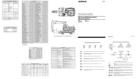
M318 and M320 Excavators Electrical System M318: 8AL2265-UP 6ES243-UP
M320: 6WL469-UP
A 19
15
25 22
C
13 24 8 2
B
6 16 D
28 12
21
10
3 19
20
11 14
23 5
26
4
1 18 9
29
27
7
18
17
Machine Harness Connector and Component Locations
©2000 Caterpillar All Rights Reserved
Harness And Wire Electrical Schematic Symbols
Electrical Schematic Symbols And Definitions
Machine locations are repeated for components located close together.
Printed in U.S.A.
A = Located Inside Of Cab
A
B = Located Inside Of RH Console
AA
D = Located Around Relay Panel
Detected Faults
Connector Location
Schematic Location
Machine Location
CONN 1
H - 14
9
CONN 2
G - 13
4
CONN 3
E - 13
8
CONN 4
C - 12
6
CONN 5
G - 12
4
CONN 6
G - 12
4
CONN 7
C -11
6
CONN 8
D - 11
6
CONN 9
E - 11
6
Connector Number
CONN 10
F - 11
6
CONN 11
C - 10
C
CONN 12
D - 10, 9, 8
6
CONN 13
H - 10
17
CONN 14
D-2
A
CONN 15
G-1
18
CONN 16
D-1
18
Error Message
Logged
Main Pump Circuit
No
Low Voltage
No
RPM Setting Diff
No
RPM Setting High
No
Off Machine Switch Specification 3E-6429 5W-9972 114-5333 116-4710 119-3399 119-3400
Primary Flow Low Brake Pressure A/C Pressure Hydraulic Oil High Temperature Coolant Temperature Hydraulic Oil Low Temperature
171-7570
Low Transmission Clutch Pressure
163-2084
AEC Swing Pressure Boom-Cyl Pressure Stick-Cyl Pressure
Actuate
Deactuate
Contact Position
4.0 grams MAX
1.5 grams MIN
Normally
(0.14 oz)
(0.05 oz)
10132 kPa (1470 psi)
--
Low 275 kPa (39.9 psi) MAX
Low 170±55 kPa (24.6±7.9 psi)
High 2800±140 kPa (406±20.3 psi)
High 1750±200 kPa (254±29 psi)
94 ºC 201 ºF 100 ºC 212 ºF
---
Open Normally
Open Open Normally Open
17 ºC
Normally
52 ºF
63 ºF
Open
(377 psi) 507 kPa (74 psi)
--
--
• Governor actuator position signal too high. • Open or shorted supply voltage circuit. • Low idle stop passed.
• Swing pump set to minimum output.
• Swing pump PRV solenoid faulty. • Open in harness wiring for swing PRV solenoid. • Harness wiring for swing PRV solenoid shorted to ground.
• Hydraulic pump outputs are reduced.
• Signal from engine speed sensor indicates engine speed is below 750 ± 25 rpm. • Engine speed sensor is not adjusted properly or is faulty. • Open in harness wiring form engine speed sensor to controller. • Harness wiring for engine speed sensor is shorted to ground. • Engine speed dial signal circuit is shorted to ground.
Yes
• Engine overload. • Engine stalls.
Yes
• Engine speed set to high idle (No effect on AEC or Heavy Lift operation).
Yes
• Heavy lift does not operate correctly.
Mode SW Open
Yes
• Power mode 1 selected no matter what the position of the power mode switch.
Mode SW Short
Yes
• Power mode 1 selected no matter what the position of the power mode switch.
Heavy Lift Circuit
Level Symbol
Flow Symbol
2
• Signal from engine speed sensor indicates engine speed is above 2150 ± 200 rpm. • Incorrect number of flywheel teeth specified in parameter settings. • Engine speed dial is faulty. • Engine speed dial signal circuit has an open. • Engine speed dial supply voltage circuit has an open or is shorted to ground. • Engine speed dial signal circuit is shorted to ground. • Heavy lift solenoid is faulty. • Open in harness wiring for heavy lift solenoid. • Harness wiring for heavy lift solenoid is shorted to ground. • Mode switch is faulty. • Open in harness wiring for mode switch. • Mode switch supply voltage circuit has an open or is shorted to ground. • Mode switch is faulty. • Short to ground in harness wiring for mode switch.
Typical representation of a Sure-Seal connector. The plugand receptacle contain both pins and sockets.
Pin or Socket Number Wire, Cable, or Harness Assembly Identification
Normally open switch that will close with an increase of a specific condition (temp-press-etc.).
Component Part Number
Single Wire Connector
Normally open switch that is closed due to an applied condition, and will open again with a specific decrease in that condition.
C
A
A 325-PK-14
Pin
Normally closed switch that will open with an increase of a specific condition.
AA 1
325-PK-14
Wire Color
Socket
2
Normally closed switch that is open due to an applied condition, and will close again with a specific decrease in that condition.
9X-1123
200-BK-14
Circuit Number Identification
The circle indicates that the component has screw terminals and a wire can be disconnected from it.
Wire Gauge
Electrical Schematic Symbols And Definitions FUSE - A component in an electrical circuit that will open the circuit if too much current flows through it.
No circle indicates that the wire cannot be disconnected from the component.
REED SWITCH - A switch whose contacts are controlled by a magnet. A magnet closes the contacts of a normally open reed switch; it opens the contacts of a normally closed reed switch.
This indicates that the component has a wire connected to it that is connected to ground. T
SENDER - A component that is used with a temperature or pressure gauge. The sender measures the temperature or pressure. Its resistance changes to give an indication to the gauge of the temperature or pressure.
Normally
11 ºC
2600 kPa
• Governor actuator position signal too low. • Open or shorted supply voltage circuit. • High idle stop passed or engine speed adjustment is loose.
• Engine speed requested does not match the actual governor actuator position.
No
Open Normally
• Battery voltage below 17 DCV.
Swing Pump
RPM Dial Setting
Function
• None • Engine operates at high idle (No effect on AEC or Heavy Lift operation). • Low idle speed too low. • Engine stall speed too high or low.
No
No
Temperature Symbol
• Main pump PRV solenoid faulty. • Open in harness wiring for main PRV solenoid. • Harness wiring for main PRV solenoid shorted to ground.
RPM Setting Low
High Engine Speed
Part No.
• Main pump set to minimum output.
Possible Causes
• High idle speed too high. • Engine stall speed too high or low.
Low Engine Speed
The connectors shown in this chart are for harness to harness connectors. Connectors that join a harness to a component are generally located at or near the component. See the Component Location Chart.
Result Of Fault
Pressure Symbol
Typical representation of a Deutsch connector. The plug contains all sockets and the receptacle contains all pins.
Receptacle
Plug
T
1 2
1 2
1
C = Located Inside Of LH Console
Normally Open Normally Open
This indicates that the component does not have a wire connected to ground. It is grounded by being fastened to the machine.
RELAY (Magnetic Switch) - A relay is an electrical component that is activated by electricity. It has a coil that makes an electromagnet when current flows through it. The electromagnet can open or close the switch part of the relay. CIRCUIT BREAKER (C/B) - A component in an electrical circuit that will open the circuit if too much current flows through it. This does not destroy the circuit breaker and it can be reset to become part of the circuit again. SOLENOID - A solenoid is an electrical component that is activated by electricity. It has a coil that makes an electromagnet when current flows through it. The electromagnet can open or close a valve or move a piece of metal that can do work.