Wire Description
Component Location Diagnostic Code Conversion
¹Code Flashed
CID-FMI
Component
Description
Schematic Location
Machine Location
D-3
C
Solenoid - Bucket Float
E-15,D-14
1
Solenoid - Engine Shutdown
2
Solenoid - Fourth Function Diverter
Alarm - Action ( EMS)
Component
Schematic Location
Machine Location
B-5
17
C-14
26
D-1,A-1
27
Wire Number
Wire Color
Wire Number
Wire Color
101
RD
Battery +
503
BR
102 105 108
Wiper - Rear (Park)
RD RD RD
Marker Lamps Key Switch Converter Output
504 505 506
YL BU PU
Wiper - Rear (Low) Wiper - Rear (High) Washer - Front
109
RD
Alt B+
507
WH
Washer - Rear
110
GN
Flasher
508
PU
Radio Speaker - Left
112
PU
Main Breaker Output
509
WH
Radio Speaker - Left (Common)
113
OR
Operator Monitor Panel
511
BR
Radio Speaker - Right
114
RD
Fwd Horn
512
GN
Radio Speaker - Right (Common)
Description Power Circuits
Description Accessory Circuits (Continued)
11
No Active Faults
Not Applicable
12
No Inactive Faults
Not Applicable
21
368-02
Auto/Manual Switch Signal Not Correct
Alternator
F-15
22
621-02
Downshift Switch Signal Not Correct
Batteries
B-15,F-15
3
Solenoid - Lift Postioner
B-5
17
24
190-08
Engine Speed Sensor Signal Not Correct
Breaker - Blower Motor
C-9
A
Solenoid - Load Check
D-1,B-1
28
25
191-08
Transmission Speed Sensor Signal Not Valid
31
641-05
Solenoid 1 Open Circuit
Breaker - Main
A-13
B
Solenoid - Ride Control
E-1,B-1
27
32
642-05
Solenoid 2 Open Circuit
Breaker - Running Lamp
A-13
B
Solenoid - Start Aid
C-14
29
33
643-05
Solenoid 3 Open Circuit
Control - Transmission Autoshift
E-10
4
Solenoid - CST Valves
F-9
30
34
644-05
Solenoid 4 Open Circuit
Connector - Data Link
E-10
10
Solenoid - Sol 1 Fwd High
F-9
30
116
BR
Rear Flood Lamps
513
OR
A/C Compressor/Refrigerant Pressure Sw
35
645-05
Solenoid 5 Open Circuit
Connector - Start Receptacle
F-13
43
Solenoid - Sol 2 Rev
F-9
30
118
GY
Wipers
515
GY
Blower Motor (HI)
36
646-05
Solenoid 6 Open Circuit
Converter - Voltage
F-6
5
Solenoid - Sol 3 Fwd Low
F-9
30
120
YL
Sw'd Converter
516
GN
Blower Motor (MED)
41
641-06
Solenoid 1 Short to Ground
Solenoid - Sol 4 Spd 1
F-9
30
517
BU
Blower Motor (LOW)
Solenoid 2 Short to Ground
C
Backup Alarm To Lamp
642-06
E-4
YL
42
Flasher
121
F-9
30
518
OR
COSA Flasher Signal
Solenoid 3 Short to Ground
Solenoid - Sol 5 Spd 2
Blower Motors
643-06
A
GN
43
C-9,A-14
124
Solenoid - Sol 6 Spd 3
F-9
30
521
YL
A/C High/Low Press Sw To Compressor
Solenoid 4 Short to Ground
B
XMSN Control
644-06
A-13
PK
44
Fuses - Alarm, Horn. Stop lamp, Key
126
Suppressor - Arc
D-14
31
522
WH
A/C Thermostat
Solenoid 5 Short to Ground
C
Aux Flood Lights
645-06
E-3
OR
45
Gauge - Engine Coolant Temp
127 128
PK
Kickout & Ride Control
537
GN
Flasher Output
46
646-06
Solenoid 6 Short to Ground
Gauge - Fuel Level
E-3
C
Switch - Air Intake Heater
F-9
A
129
BU
Cigar Lighter
538
BR
Flasher Output
51
641-03
Solenoid 1 Short to + Battery
Gauge - Hydraulic Oil Temp
E-3
C
Switch - Beacon
E-8
A
130
GN
Stop Lamps
52
642-03
Solenoid 2 Short to + Battery
Gauge - Torque Conv Temp
F-3
C
Switch - Blower
D-4
C
135
BU
Sw'd Converter Output
603
PK
Beacon
53
643-03
Solenoid 3 Short to + Battery
6
Switch - Brake Oil Press (EMS)
F-8
32
Beacon & Heated Seat
604
OR
Stop Lamp
Solenoid 4 Short to + Battery
C-2,F-1
33
Start Aid Rly - AIH Lamp
605
YL
Left Turn
Solenoid 5 Short to + Battery
Switch - Bucket Postioner
PU
645-03
7
160
55
164
WH
XMSN Cont To Data Link
606
GY
Right Turn
56
646-03
Solenoid 6 Short to + Battery
Ground - Engine To Block
D-9,C-8,C-5 B-15,A-6 A-5,F-13 F-14
GN
644-03
Ground - Platform
144
54
29
Switch - Dimmer (COSA only)
A-3
40
193
PU
Ride Control/Dvtr
608
GN
Rear Flood Lamps
61
660-02
Invalid Shift Lever Input Line 12 Invalid Shift Lever Input Line 13
5
Switch - Disconnect
B-15
3
Dimmer Switch
661-02
F-7,E-6
OR
62
Ground - Roof
610
63
662-02
Invalid Shift Lever Input Line 14
D-11
8
Switch - Engine Coolant Temp (EMS)
F-12
2
64
663-02
Invalid Shift Lever Input Line 15
65
664-02
Invalid Shift Lever Input Line 16
66
665-02
Invalid Shift Lever Input Line 17
Lamp - Action LED (Trans)
67
666-02
Invalid Shift Lever Input Line 18
Lamp - Dome
68
667-02
Invalid Shift Lever Input Line 19
69
668-02
Invalid Shift Lever Input
71
168-00
System Voltage Above Normal
Lamp - Master Action (EMS)
72
168-01
System Voltage Below Normal
74
650-02
Invalid Harness Code
Alarm - Backup
Fuses
Ground - Engine End Frame
Heater - Air Intake
¹Codes given using the Diagnostic Indicator for a specific CID-FMI.
Lighting Circuits
Ground Circuits 200
BK
Main Chassis
611
PU
High Beam Headlights
201
BK
Operator Monitor Panel
614
PU
Park/Tail/Dash Lamps
Horn - Forward
E-1
9
Switch - Engine Coolant Temp (Start Aid)
F-12
2
202
BK
Controller
615
YL
Cab Flood Lights
Lamp - Air Intake Heater
F-3
C
Switch - Engine Oil Press (EMS)
B-14
31
206
BK
Battery Side Of Disconnect
617
BR
LH Head/Position/Turn - Tail Lamps
E-10
10
Switch - Flood Lamp
D-7
A
276
BK
XMSN Ident Code 0
619
GN
Low Beam Headlights
F-6 F-15,E-15 E-14,C-14 D-3
A
Switch - Fork Postioner
C-2,F-1
33
277
BK
XMSN Ident Code 1
7
Switch - Forward Horn
D-5
24
278
BK
XMSN Ident Code 2
710
GN
XMSN Speed
279
BK
XMSN Ident Code 3
720
PU
Neutralizer Sw
C
Switch - Forth Function Diverter
E-7
A
280
BK
XMSN Ident Code 4
751
GN
XMSN Solenoid 1
Lamp - Ride Control
F-3
C
Switch - Front Intermittent Wiper/ Washer
E-6
A
281
BK
XMSN Ident Code 5
752
YL
XMSN Solenoid 2
Lighter - Cigar
E-8
A
Switch - Front Wiper/ Washer
D-8
A
754
BU
XMSN Solenoid 3
Meter - Service
E-7
A
Switch - Hydraulic Lock/Detent Override
A-8
A
Meter - Speedometer
F-4
C
Switch - Fuel Press (EMS)
B-14
26
Monitor - Operator (EMS)
E-3
C
Switch - Key Start
D-6
A
Motor - Blower
C-3
11
Switch - Kickout Neutralizer
D-9
Motor - Front Washer
F-8
12
Switch - Lift Positioner
Motor - Front Wiper
C-4
13
Motor - Rear Washer
F-8
Motor - Rear Wiper
Lamp - Flood
Basic Machine Circuits BU
Shutdown Sol
755
OR
XMSN Solenoid 4
304
WH
Start Relay Output
761
GY
Lift Positioner Sol
306
GN
Start Relay
762
YL
Bucket Positioner Sol
307
OR
Key Switch Start
900
PU
XMSN Solenoid 5
A
308
YL
Main Relay
901
WH
XMSN Solenoid 6
C-2,F-1
34
310
PU
Start Aid Signal
910
YL
XMSN Neutralizer Override Indicator
Switch - Load Check Press
B-6
17
321
BR
Backup Alarm
921
WH
XMSN Solenoid 1 Return
12
Switch - Neutralizer
A-3
35
322
GY
Fwd Horn
922
BR
XMSN Solenoid 2 Return
E-9
14
Switch - Parking Brake (EMS)
D-10
36
326
PU
Key Switch Off - "C" Terminal
923
GY
XMSN Solenoid 3 Return
Motor - Starting
F-13
15
Switch - Positioner Select Bucket/Fork
E-8
A
373
GN
AIH Timer
924
GN
XMSN Solenoid 4 Return
925
YL
XMSN Solenoid 5 Return
Radio
F-7
16
Switch - Primary Steering Press (EMS)
A-15
37
403
GN
Alternator (R) Terminal
926
BU
XMSN Solenoid 6 Return
Relay - Air Intake Heater
D-11
15
Switch - Rear Wiper/ Washer
D-8
A
404
YL
XMSN Oil Temperature Indicator
944
OR
CAT DATA LINK+
Relay - Main
A-13
B
Switch - Refrigerant High/ Low Press (AC)
D-15
25
405
GY
Engine Oil Pressure
945
BR
CAT DATA LINK-
Relay - Load Check
A-6
17
Switch - Ride Control
E-7
A
406
PU
Coolant Temperature Indicator
963
GN
Bucket Positioner Sol
Relay - Ride Control
A-8
18
Switch - Ride Control Interrupt Press
A-8
37
417
GY
Steering Pressure
964
BU
Fork Position Select
Relay - Start
A-14
B
Switch - Running Lamp
D-7
A
409
OR
Operator Monitor Neutral
965
WH
Trans Sol 1 Sw To Ground
Resistor - Alternator
A-13
B
Switch - Secondary Steering
A-15
35
410
WH
Operator Monitor Action Alarm
966
GY
Trans Sol 3/Fwd Sw To Gnd
411
PK
Operator Monitor Action Lamp
967
BU
Fwd Park Sw To B+
Resistor - Blower Motor Speed
C-13
11
Switch - Start Aid
E-9
A
413
BR
Operator Monitor Fuel Pressure
968
BR
Trans Sol 2/Rev Sw To Gnd
415
GN
Operator Monitor Test Sw
969
YL
Trans Sol 2/Rev Park Sw
416
OR
Secondary Steering Sw
970
GN
Trans Sol 4/Speed 1 Sw To Gnd
417
GY
Primary Steering Sw
971
YL
Trans Sol 5/Speed 2 Sw To Gnd
419
YL
Operator Monitor Test Sw
972
BU
Trans Sol 6/Speed 3 Sw To Gnd
428
OR
Operator Monitor Test Sw
973
BR
XMSN Cont - Auto/Manual Sw 2
432
PK
Operator Monitor Test Sw
974
PU
XMSN Cont - Slow Mode Sw 2
Monitoring Circuits
Sender - Engine Coolant Temp (Gauge)
C-3
2
Switch - Stop Lamp
A-3
35
Sender - Fuel Level (Gauge)
E-12
19
Switch - Supplemental Oil Flow (EMS)
A-15
37
Sender - Hydraulic Oil Temp (Gauge)
B-13
20
Switch - Test (EMS)
E-8
A
Sender - Torque Converter Temp (Gauge)
B-13
21
Switch - Thermostat
C-3
11
Sensor - Engine Speed (Trans)
B-10
22
Switch - Torque Converter Oil Temp (EMS)
B-13
21
Sensor - Trans Speed (Speedometer)
F-10
23
Switch - Transmission Auto/ Manual
E-8
A
441
OR
Engine Coolant Temp Gauge
975
WH
XMSN Cont - Solenoid Return
Shifter - Transmission
F-10
24
Switch - Transmission Downshift
B-6
38
442
GY
Hydraulic System Temp Gauge
976
OR
Ride Control Output
Solenoid - Air Conditioner Clutch
F-5
25
Switch - Transmission Neutralizer Override
E-8
A
443
YL
Converter Oil Temp Gauge
977
YL
XMSN Cont - Auto/Manual Sw 1
D-15
17
Switch - Turn Signal
E-5
24
447
PK
Fuel Level Gauge
978
GN
Downshift Signal
B-6
17
Timer - Air Intake Heater
E-9
A
449
BU
Speedometer Signal
987
WH
Diverter Sol
450
YL
Tachometer Signal
B757
WH
Unused A/S Sw
B758
GN
Unused A/S Sw
Solenoid - Bucket Postioner
Machine locations are repeated for components located close together.
B = Located in console.
A = Located inside of cab.
C = Located inside relay panel.
Accessory Circuits 500
BR
Wiper - Front (Park)
B766
WH
Kickouts/Detent Disable Sw To Kickouts
501
GN
Wiper - Front (Low)
C920
GY
XMSN Control - Diagnostic Indicator
502
OR
Wiper - Front (High)
Operation
Contact 1¹
Contact 3¹
Contact 5¹
Ground²
Open
Open
To Scroll INACTIVE Faults
Open
Open
Ground²
To Clear ³ Faults
Open
Ground
Open
Connector Location
³A fault is cleared only while it is on-hold. A fault that is active cannot be cleared.
12
1
35
15
19
2 25
8
23
42 22
26 29 31
B
40
6
10
17 18
C
27
13
11
39
43
28
5 44
24
30
21 45
Form Number SENR5751
37
4
14
Related Electrical Service Manuals
Electronic Transmission Control
7
20
41
3
32
36
47
SENR3685
28
38 A
34
16 46
33 9
(CST Autoshift) Electric Starting Motor:
3E-5381
SENR3828
Operator Monitor (EMS)
8C-3508
SENR2945
Component Description
3E-1906
Solenoid:
A/C Compressor
3E-6332
Solenoid:
Valve - Start Aid
3E-6269
Solenoid:
Valve - CST
4W-9972
Sender:
Electrical Schematic Symbols And Definitions Resistance (Ohms)¹ 17.6 ± 0.6 6.0
T
33.8 ± 1.0
Hydraulic Gauge
560 to 716 @54.4°C
Converter Oil Temperature Gauge
72.1 to 81.8 @ 110°C
5 44
16
24
14 38
47
1
43
29 2 25 3 19
41
26
20
8
42
31
15
36
4
17
10 39
22 B
34
21
C
A
33
11
6 18
45
13
32 30 23
46
12 7 35 40
28
9
27
37
Resistor:
Alternator
Solenoid:
Engine Shutdown
Pressure Symbol
10.3 ± 1.03 Blower Motor Speed
Overall 2.0 ± .1; Tap 1.0 ± .05
CONN 1
D-15
41
9X-3267
Solenoid:
Valve - Ride Control
13.8 ± .4
CONN 2
D-14
41
109-1739
Solenoid:
Bucket Float
85.3 ± 5.0
CONN 3
A-14
1
CONN 4
A-14
1
CONN 5
A-13
B
CONN 6
B-13
4
CONN 7
D-13
41
CONN 8
F-13
43
CONN 9
F-13
15
CONN 10
C-12
6
CONN 11
C-12
42
CONN 12
C-11
42
CONN 13
E-10
43
CONN 14
E-10
10
CONN 15
C-10
39
CONN 16
B-10
12
CONN 17
B-9
45
CONN 18
B-9
39
CONN 19
D-9
39
CONN 20
D-9
16
CONN 21
E-9
A
CONN 22
E-8
A
CONN 23
B-8
39
CONN 24
A-8
39
CONN 25
A-8
39
CONN 26
A-7
39
CONN 27
B-7
17
CONN 28
B-7
39
CONN 29
E-6
23
CONN 30
C-6
39
CONN 31
C-6
39
CONN 32
B-6
39
CONN 33
A-6
39
CONN 34
B-5
39
CONN 35
E-5
24
CONN 36
E-5
C
CONN 37
C-4
A
CONN 38
A-3
40
CONN 39
B-3
40
CONN 40
B-3
40
CONN 41
D-2
27
CONN 42
D-2
27
CONN 43
B-2
27
CONN 44
B-2
27
CONN 45
A-2
27
Normally open switch that will close with an increase of a specific condition (temp-press-etc.). The circle indicates that the component has screw terminals and a wire can be disconnected from it.
39 ± 1.95
Resistor:
Normally closed switch that will open with an increase of a specific condition. No circle indicates that the wire cannot be disconnected from the component.
Bucket Positioner
This indicates that the component has a wire connected to it that is connected to ground.
Lift Positioner 134-9878
Solenoid:
141-2633
Sender:
Circuit Breaker Symbol
Flow Symbol
Level Symbol
Temperature Symbol
1.55 ± 0.15
9G-1950
CONN 46 E-1 27 The connectors shown in this chart are for harness to harness connectors. Connectors that join a harness to a component are generally located at or near the component. See the Component Location Chart.
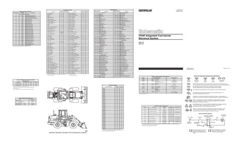
Machine Harness Connector And Component Locations
6T-7864 8C-3663
Machine Location
Connector Number
during scrolling on-hold.
Alternator: 9W-3043
Resistor, Sender and Solenoid Specifications
Schematic Location
²Remove the connection to ground in order to place the desired information shown
Printed in U.S.A.
© 2000 Caterpillar All Rights Reserved
Coolant Gauge
¹These contacts are located in the harness code connector.
Title
4NN1-UP 6KN1-UP
Part No.
Activation Of Diagnostic Indicator Operations (Quick Reference) To Scroll ACTIVE Faults
IT24F Integrated Tool Carrier Electrical System
Control Circuits
301
Solenoid - Bucket Float
SENR6737-01 September 2000
Valve - Ride Control
13.8 ± .4
Fuel Level
Empty: Full:
240 to 260
This indicates that the component does not have a wire connected to ground. It is grounded by being fastened to the machine.
27.5 to 39.5
¹ At room temperature.
Reed Switch - A switch whose contacts are controlled by a magnet. A magnet closes the contacts of a normally open reed switch; it opens the contacts of a normally closed reed switch. Sender- A component that is used with a temperature or pressure gauge. The sender measures the temperature or pressure. Its resistance changes to give an indication to the gauge of the temperature or pressure.
T
Part No.
Off Machine Switch Specification
Function
Actuate
Deactuate
Contact Position
1.5 grams (.05 oz)
Normally Open
27° C Min.
Normally Closed
3E-6429
Supplemental Steering Oil Pressure
4 grams (.14 oz)
3E-6449
Start Aid Coolant Temperature
38 ± 3° C (100 ± 5° F)
(80.6° F)
3E-6450
Primary Steering Oil Pressure
1200 kPa MAX
700 ± 100 kPa
A-C, Normally Closed
(175 psi MAX)
(100 ± 15 psi)
A-B, Normally Open
107.0 ± 3.0° C
93° C Min.
Normally Closed
(224.6 ± 5.4° F)
(199.0° F MIN)
3E-6451 3E-6453 3E-6454 3E-6455 3E-7693
Engine Coolant Temperature (EMS) Torque Converter Oil Temperature (EMS) Fuel Pressure (EMS) Engine Oil Pressure (EMS) Service Brake Oil Pressure
129.0 ± 3.0° C
118° C Min.
(264.0 ± 5.4° F)
(244.0° F MIN)
Relay (Magnetic Switch) - A relay is an electrical component that is activated by electricity. It has a coil that makes an electromagnet when current flows through it. The electromagnet can open or close the switch part of the relay. Solenoid - A solenoid is an electrical component that is activated by electricity. It has a coil that makes an electromagnet when current flows through it. The electromagnet can open or close a valve or move a piece of metal that can do work.
Harness And Wire Symbols
Normally Closed
70 kPa MAX
40 ± 20 kPa
A-C, Normally Closed
(10 psi MAX)
(6.0 ± 3.0 psi)
A-B, Normally Open
90 ± 21 kPa
70 ± 21 kPa
A-C, Normally Closed
(13 ± 3.0 psi)
(10 ± 3.0 psi)
A-B, Normally Open
10700 kPa MAX
8960 ± 345 kPa
A-B, Normally Open
(1500 psi MAX) (1300 ± 50 psi) A-C, Normally Closed 114-5333 Refrigerant Pressure (AC) 275 to 1750 kpa¹ -Normally Open ² (40 to 255 psi) -¹ A hysteresis band exists: with increasing pressure the closed condition can be maintained up to 2800 kpa (405 psi), with decreasing pressure the closed condition can be maintained down to 170 kpa (25 psi).
Pin
Socket
Wire Color
A
Circuit Number Identification
² Contact position at the contacts of the harness connector.
105-9344
Receptacle
Wire Gauge
Ground Connection
Fuse
AA 1
325-PK-14
Single Wire Connector
Component Part Number
Wire, Cable, or Harness Assembly Identification
Plug
2
200-BK-14
Pin or Socket Number 1 2
Typical representation of a Deutsch connector. The plug contains all sockets and the receptacle contains all pins.
1 2
Typical representation of a Sure-Seal connector. The plug and receptacle contain both pins and sockets.