Component Identifiers (CID) List CID No.
Wire Number
Wire Color
101
RD
102
Wire Description
Wire Color
Bat (+)
512
GN
Radio Speaker - Right (Common)
BU
Hd Lmp
513
OR
A/C Compressor/Refrigerant Pressure SW
105
BR
Key Sw
515
GY
Blower Motor (Hi)
Power Circuits
Component Caterpillar Monitoring System MID 30
Description Accessory Circuits (Continued)
096
Fuel Level Sensor
108
BU
Aux Ckt
516
GN
Blower Motor (Medium)
110
Engine Coolant Temperature Sensor
109
OR
Alt Output (+) Term.
517
BU
Blower Motor (Low)
177
Torque Convertor Oil Temperature Sensor
112
PU
Main Power RIy Output
521
YL
A/C SW To Refrigerant SW
248
Data Link
113
OR
Opr Mon Panel B+ Switched
522
WH
A/C Clutch To Thermostat SW
263
8 Volt Sensor Power Supply
114
GN
Warning Horn (Forward)
523
BR
Wiper - Left (Park)
116
OR
Aux Ckt
524
BU
Wiper - Left (Low)
271
Action Alarm
124
GN
A/C
525
GY
Wiper - Left (Hi)
324
Action Lamp
129
BU
Aux Ckt
526
YL
Wiper - Right (Park)
600
Hydraulic Oil Temperature Sensor
140
BU
Aux Ckt
527
GN
Wiper - Right (Low)
601
Brake Air Pressure
158
BR
Aux Ckt
528
PK
Wiper - Right (Hi)
819
Display Data Link
176
OR
Aux Ckt
529
WH
Washer Left
197
GN
Aux Ckt
530
OR
Washer Right
821
9 Volt Display Power Supply
198
PK
Aux Ckt
592
BU
DC/DC Converter Power Output
830
Brake Oil Temperature
199
OR
Aux Ckt
593
GN
Condensor Fan Relay To Motors
Connector Location¹
200
BK
Main Chassis
600
BR
Dash Lamp Basic
201
BK
Operator Monitor Return
608
GN
Flood Lamp - Rear
202
BK
XMSN Ctrl
609
YL
Flood Lamp - Side
203
BK
Chassis Diagnostic
610
OR
Head Lamp Basic
207
BK
Starter Diagnostic
663
GY
Gauge Lamps
270
BK
CMS ldent Code 0
Schematic Location
Machine Location
CONN 1
C-12
29
CONN 2
C-12
30
CONN 3
D-12
31
CONN 4
F-12
26
CONN 5 ECB Harness Code
C-11
C
CONN 6
D-11
36
CONN 7
A-10
30 30
Connector Number
Lighting Circuits
Ground Circuits
Power Train Electronic Control System MID 113
SENR1728 July 1997
Wire Number
Description
070
Parking Brake Switch
075
Steering System Oil Temperature Sensor
168
Electrical System
177
Transmission Oil Temperature Sensor
190
Engine Speed Sensor
271
BK
CMS ldent Code 1
709
OR
Sensor Power Supply
CONN 8
B-10
248
Data Link
272
BK
CMS ldent Code 2
751
GN
XMSN Shift Sol No. 1 Or 3
CMS ldent Code 3
752
YL
XMSN Shift Sol No. 2
D
Electronic Control Module
BK
F-10
254
273
CONN 9
CMS ldent Code 4
754
BU
XMSN Shift Sol No. 3 Or 1
21
Sensor Power Supply
BK
A-9
269
274
CONN 10
CMS ldent Code 5
755
OR
XMSN Shift Sol No. 4 Or 5
B-9
21
Service Brake Switch
BK
CONN 11
298
275 276
BK
XMSN Ctrl Ident Code 0
851
WH
Hydrst Speed And Direction Sensor
299
Direction Selector Position Sensor
277
BK
XMSN Ctrl Ident Code 1
892
BR
Mon Start Mod Right (-) Port/CAT Data Link (-)
CONN 12 Diagnostic
368
Autoshift Switch - Power Train
278
BK
XMSN Ctrl Ident Code 2
893
GN
Mon Start Mod Right (+) Port/CAT Data Link (+)
468
Service Brake Pedal Position Sensor
279
BK
XMSN Ctrl Ident Code 3
900
PU
573
Inching Pedal Position Sensor
280
BK
XMSN Ctrl Ident Code 4
973
BR
618
Parking Brake Switch
290
BK
CMS Service
975
WH
CST Autoshif t- Sol Return
621
Downshift Switch
291
BK
CMS Clear
977
YL
CST Autoshift- Auto/Manual SW 1
C413
YL
Display Data
622
Upshift Switch
301
BU
Starter No. 1 Sol
C414
BU
Display Load
623
Reverse Switch
302
OR
Starter No. 1 Resistor To Diagnostic
E707
GN
Display +V
650
Harness Code
304
WH
Starter Relay No. 1 Output
E708
pk
Display Clock
306
GN
Starter Relay Coil To Neut Start SW Or Key SW
E735
PU
Tack/Serv Mtr/Odometer Select
307
OR
Key SW To Neut Start SW
E900
WH
Trans Output SPD +
Control Circuits
Basic Machine Circuits
F-9
26
XMSN Shift Sol No. 4
CONN 13 Aux Ckt Plug
D-13
30
CST Autoshift- Auto/Manual SW 2
CONN 14
A-8
32
CONN 15
B-8
37
CONN 16
B-7
37
CONN 17 Winch Lamp
B-5
33
CONN 18
B-5
22
CONN19 Harness Code
B-5
A
CONN 20 Monitor Service
C-5
A
CONN21 Datalink Service
C-5
A
CONN 22
E-5
A A
671
Transmission Output Speed 1 Sensor
672
Torque Converter Output Speed Sensor
308
YL
Main Power Relay Coil
E901
GN
Trans Output SPD -
673
Transmission Output Speed 2 Sensor
310
PU
Start Aid SW To Start Aid Sol
E902
PU
Trans Intermediate SPD +
674
Transmission Intermediate Speed 1 Sensor
311
WH
Start Aid Sol To Temp SW
E903
YL
Trans Intermediate SPD -
675
Transmission Intermediate Speed 2 Sensor
321
BR
Bckp Alarm Lamp
E904
BR
Trans Intermediate SPD 0+
676
Left Steering Lever Position Sensor
322
GY
Warning Horn (Forward)
E905
BU
Trans Intermediate SPD Q -
677
Right Steering Lever Position Sensor
334
BU
Start Aid Sot #2
E906
OR
Trans Output SPD Q+
337
WH
Prelube Pushbutton SW To Prelube Timer
E907
GY
Trans Output SPD Q -
CONN 23
B-3
681
Parking Brake Solenoid
E908
BR
Trans Input SPD +
CONN 24
D-3
A
689
Left Steering Brake Solenoid
CONN 25
D-3
34
690
Right Steering Brake Solenoid
CONN 26
D-2
35
691
Reverse Clutch Solenoid Valve 1
CONN 27
E-2
34
692
Forward Clutch Solenoid Valve 2
CONN 28
F-2
34
693
CONN 29
F-1
35
Monitoring Circuits 403
GN
Alternator (R) Term.
E909
WH
Trans Input SPD -
405
GY
Opr Mon Oil Press. (Low Setting)
F780
PK
Parking Brake SW
410
WH
Opr Mon Action Alarm
F781
BR
Downshift SW (NO.)
411
PK
Opr Mon Master
F782
OR
Reverse SW (NO.)
419
YL
Opr Mon Parking Brake
F783
GN
Upshift SW (NC.)
Speed 3 Clutch Solenoid Valve 3
426
BR
Opr Mon Power Train Oil Filter
F784
YL
Downshift SW (NC.)
694
Speed 2 Clutch Solenoid Valve 4
441
OR
Eng Coolant Temp Gauge
F785
WH
Upshift SW (NO.)
695
Speed 1 Clutch Solenoid Valve 5
442
GY
Hyd System Temp Gauge
F786
GY
Reverse SW (NC.)
697
Priority Valve Solenoid
443
YL
Power Train Temp Gauge
F788
PU
Left Steer Clutch
698
Left Steering Clutch Solenoid Valve
447
PK
Fuel Level Gauge
F789
YL
Right Steer Clutch
450
YL
Tach Sender (+)
F790
BR
Service Brake Pedal
699
Right Steering Clutch Solenoid Valve
F791
BU
Right Brake Solenoid
718
Transmission Unidentifiable Failure Mode
722
Secondary Brake Solenoid Valve
Accessory Circuits BR
Wiper - Front (Park)
F792
WH
Left Brake Solenoid
501
GN
Wiper - Front (Low)
F842
BU
Post Heat
502
OR
Wiper - Front (HI)
F843
YL
Inching Pedal
503
BR
Wiper - Rear (Park)
F846
PU
LED Driver 1
504
YL
Wiper - Rear (Low)
F847
YL
ECB SW IP1
505
BU
Wiper - Rear (HI)
F848
OR
ECB SW 1P2
506
PU
Washer - Front
F849
WH
ECB SW lP3
507
WH
Washer - Rear
F850
PK
ECB SW lP4
508
PU
Radio Speaker - Left
G730
PK
Park Brake Sol
509
WH
Radio Speaker - Left (Commom)
G731
GY
Secondary Service Brake Sol
511
BR
Radio Speaker - Right
G848
GN
LED Driver 2
G939
PK
Switch Return
K977
PK
Trans Oil Temp Sensor
K978
BU
Pump Sol
Failure Description
0
Data valid but above normal operational range.
1
Data valid but below normal operational range.
2
Data erratic, intermittent, or incorrect.
3
Voltage above normal or shorted high.
4
Voltage below normal or shorted low.
5
Current below normal or open circuit.
6
Current above normal or grounded circuit.
7
Mechanical system not responding properly.
8
Abnormal frequency, pulse width, or period.
9
Abnormal update.
10
Abnormal rate of change.
11
Failure mode not identifiable.
12
Bad device or component.
13
Out of calibration.
30
D
4 36
11
27
C 24 25
21
37
7
A
33
2
14
5
32
31 1 18
Related Electrical Service Manuals Title
Form Number
Alternator 132-2156
SENR4547
Caterpillar Monitoring System
SENR6717
Starting And Charging Systems
SENR2947
Starting Motor 6V-5227: Consist: 6V-5537 106-8552 6V-5538
SENR3581 SENR3536 SENR4975
Electronic Clutch Brake Control
SENR8367
37 28
8
10
12
36
9
Mode Number 0
Harness Code
1
Numeric Readout
2
Service
3
Tattletale (Log)
4
Steering Brake Calibration
5
Transmission Calibration
6
Component Data Display
7
Charging System Display
8
Sensor - Brake Position
A-5
22
Alternator
B-1
2
Sensor - Direction
F-7
C
Battery
F-12
3
Sensor - Lever Position (Left)
F-7
C
Breaker - Alternator (80A)
E-11
D
Sensor - Lever Position (Right)
F-7
C
Breaker - Aux (20A)
E-11
D
Sensor - Transmission Temp
A-6
23
Breaker - Blower (20A)
F-11
D
Solenoid - A/C Clutch
B-1
5
Caterpillar Monitor
C-4
A
Solenoid - ECPC Pump
A-11
24
Control - ECB
B-11
C
Solenoid - First Gear Clutch 5
B-8
21
Converter - 24V to 12V
D-10
4
Solenoid - Forward Clutch 2
B-8
21
B-1
5
Solenoid - Left Brake
C-8
25
E-11
D
Solenoid - Left Steer Clutch
C-8
25
Gauge Cluster
C-4
A
Solenoid - Park Brake Dump
C-8
25
Horn - Forward (2)
F-1
6
Solenoid - Reverse Clutch 1
B-8
21
Indicator - Auto Downshift
B-6
A
Solenoid - Right Brake
C-8
25
Indicator Strip
C-6
A
Solenoid - Right Steer Clutch
B-8
25
Lamp - Action
C-4
A
Solenoid - Second Gear Clutch 4
B-8
21
Lamp - Pipe
D-4
A
Solenoid - Serv Brake Dump
C-8
25
Motor - Blower (2)
B-3
7
Solenoid - Third Gear Clutch 3
B-8
21
B-12
8
Starter
C-2
14
D-7
C
Switch - Auto Downshift
B-6
A
D-11
9
Switch - Bidirectional Mode
B-6
A
Motor - Wiper (Front)
E-4
10
Switch - Blower
C-6
A
Motor - Wiper (Left)
E-5
11
Switch - Console Raise/Lower
D-7
C
Motor - Wiper (Rear)
D-8
12
Switch - Disconnect
F-12
26
Motor - Wiper (Right)
B-6
13
Switch - Downshift
E-7
C
Relay - Condenser
B-12
8
Switch - Engine Oil
D-2
27
Relay - Main
F-11
D
Switch - Horn (Forward)
B-5
B
Relay - Start
F-11
D
Switch - Key Start
C-5
A
Resistor (Gauge Cluster)
D-4
A
Switch - Lamp
D-5
A
Part No.
Resistor (Starter)
C-2
14
Switch - Operator Monitor
B-5
A
3E-5239
Relay - Condensor
Motor - Washer (Front, Rear. Left, Right)
17
Normal
1
Motor - Console Raise/Lower
B
Monitoring System Mode
D-12
Motor - Condenser (2)
29
Mode Of Operation
Alarm - Backup
Fuses
13
1
33
30 3
4
A
C
32 D
22
31
11
15
16
2
13
34 25
35 20
14
6
5 27
Component Sender - Trans Output Speed 2
Schematic Location A-9
Machine Location 21
T
Pressure Symbol Part No.
Function
Off Machine Switch Specification Actuate
Deactuate
Power Train Filter Pressure
Resistor, Sender and Solenoid Specifications Component Description
E-7
C
101-7740
Relay - Main Power
53. ± 5.3
Switch - Power Train Filter
A-8
27
125-1302
Relay - Start
27.5 ± 2.8
116-6203
Resistor - Gauge
C-1
5
Switch - Reverse
D-7
C
Sender - Hydraulic Oil Temp
A-8
18
Switch - Service Brake Pedal
B-5
22
Sender - Powertrain Oil Temperature
A-11
19
Switch - Start Aid
C-6
A
Sender - Trans Input Speed
A-11
20
Switch - Upshift
E-7
C
Sender - Trans Intermediate Speed 1
A-9
21
Switch - Wiper (Front, Rear, Left, Right)
A-7, A-8
28
Sender - Trans Intermediate Speed 2
A-9
21
Thermostat
B-3
5
Sender - Trans Output Speed 1
A-9
21
Solenoid - A solenoid is an electrical component that is activated by electricity. It has a coil that makes an electromagnet when current flows through it. The electromagnet can open or close a valve or move a piece of metal that can do work.
360
Switch - Parking Brake Switch - Refrigerant
Sender- A component that is used with a temperature or pressure gauge. The sender measures the temperature or pressure. Its resistance changes to give an indication to the gauge of the temperature or pressure.
Resistance (Ohms)¹
7
17
This indicates that the component does not have a wire connected to ground. It is grounded by being fastened to the machine.
Relay (Magnetic Switch) - A relay is an electrical component that is activated by electricity. It has a coil that makes an electromagnet when current flows through it. The electromagnet can open or close the switch part of the relay.
15 16
This indicates that the component has a wire connected to it that is connected to ground.
T
B-3 E-1
Normally closed switch that will open with an increase of a specific condition. No circle indicates that the wire cannot be disconnected from the component.
Reed Switch - A switch whose contacts are controlled by a magnet. A magnet closes the contacts of a normally open reed switch; it opens the contacts of a normally closed reed switch.
D-2 D-12
Normally open switch that will close with an increase of a specific condition (temp-press-etc.). The circle indicates that the component has screw terminals and a wire can be disconnected from it.
210 ± 70 kPa Normally Open (30 ± 10psi) 275 to 1750 kPa ¹ 114-5333 Refrigerant Pressure (AC) Normally Open ² (40 to 255 psi) 60 kPa MAX 38 ± 20 kPa 3E-2026 Engine Oil Pressure Normally Open (8.7 psi MAX) (5.5 ± 2.9 psi) 38 ± 3°C 27 °C MIN 3E-6425 Coolant Temperature (Start Aid) Normally Closed (100.4° ± 5.4°F) (80.6°F MIN) ¹A hysteresis band exists: with increasing pressure the closed condition can be maintained up to 2800 kpa (405 psi), with decreasing pressure the closed condition can be maintained down to 170 kpa (25psi). ² Contact postion at the contacts of the harness connector. 9X-7781
Circuit Breaker Symbol
Flow Symbol
Level Symbol
Temperature Symbol
Contact Position
Sender - Coolant Temp Sender - Fuel Level
18
Machine Location A
Resistor - Blower Sender - Engine Speed
7 26
Printed in U.S.A.
Electrical Schematic Symbols And Definitions
Alarm - Action
Diode (A/C Clutch) 35
28
B
10
22
23
¹The FMI is a diagnostic code that indicates what type of failure has occurred.
6 15
20
19
8 12
17
16
34
Component Location
Schematic Location A-4
Component
26
9
8XN1-UP 4JR1-UP 6MR1-UP
©1997 Caterpillar All Rights Reserved
3
29
2HM1-UP 2YN1-UP 4HN1-UP 4MN1-UP 6JN1-UP 8LN1-UP
¹The connectors shown in this chart are for harness to harness connectors with a minimum of four contacts and other special connectors. Connectors that join a harness to a component are generally located at or near the component. See the Component Location Chart.
500
Failure Mode Identifiers (FMI¹) List
FMI No.
D6R Tractor (Electronic Clutch Brake) Electrical System
20 ± 1
Harness And Wire Symbols
Overall 2.0 ± .1; Tap 1.0 ± .05
9G-1950
Resistor - Blower Motor Speed
3E-7842
Resistor - Starter/Diagnostic Conn
150 ± 7.5
134-3999
Solenoid - A/C Clutch
17.6 ± 0.6
3E-6332
Solenoid - Start Aid
6.0
Pin
Socket
Wire Color
Component Part Number
Wire, Cable, or Harness Assembly Identification A
¹ At room temperature.
Fuse
AA
105-9344
1
325-PK-14
Machine location are repeated for components located close together 19
21 23
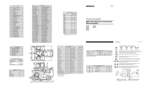
A = Operator Compartment - Front Dash B = Operator Compartment - Right Console C = Operator Compartment - Left Console
Single Wire Connector
Circuit Number Identification
Ground Connection
D = Operator Compartment - Fuse Panel
Plug
2
200-BK-14
Pin or Socket Number
24
1 2
Machine Harness Connector and Component Locations
Receptacle
Wire Gauge
Typical representation of a Deutsch connector. The plug contains all sockets and the receptacle contains all pins.
1 2
Typical representation of a Sure-Seal connector. The plug and receptacle contain both pins and sockets.